Ladder Logic Programming: A Comprehensive Guide
Modern industrial automation demands robust and reliable control systems. Ladder logic programming is a cornerstone of PLC-based automation, combining traditional relay logic with advanced digital capabilities. This guide explores everything engineers should know about ladder logic programming

Last updated on 20 Nov, 2024. 15 minutes read
With its intuitive visual representation and logical structure, ladder logic resembling to electrical relay circuits, ladder logic programming has become a standard in the field to develop complex control systems
Introduction
Ladder logic programming stands as the fundamental programming language for Programmable Logic Controllers (PLCs), powering approximately 80% of industrial automation systems worldwide. It’s a visual programming methodology that evolved from traditional relay-based control systems, provides an intuitive approach to implementing complex control logic in manufacturing processes. The purpose of ladder logic programming is to simplify the process of programming and controlling complex machinery, such as assembly lines and manufacturing equipment. The transition from physical relay panels to digital programming has maintained the familiar ladder diagram format while incorporating advanced digital capabilities, making it the preferred choice for automation engineers and technicians.
In today's Industry 4.0 landscape, ladder logic programming continues to demonstrate its crucial role, with recent studies indicating a 15% annual growth in PLC implementations across manufacturing sectors. The language's inherent reliability and accessibility have led to its adoption in over 90% of discrete manufacturing processes globally, while its integration capabilities with modern technologies like the Industrial Internet of Things (IIoT) and cloud systems ensure its ongoing relevance in smart manufacturing environments.
Suggested Reading: 6 Types of Automation: A Comprehensive Guide for Engineers
How Ladder Logic Programming Works
PLCs work using binary signals, each of which can be set to zero or one, just like computers. This form of data is referred to as a boolean in the field of programming. The majority of fundamental PLC commands use booleans, which only require one memory bit and may be changed to 0 or 1.
One rung at a time, the PLC runs the program that has been loaded into it. The PLC reads the instructions on the left and checks to see if the logic on that side of the rung is set to TRUE when it starts to process the rung. When a fictitious current can flow through the instructions, the logic evaluates to TRUE. Each instruction is TRUE or FALSE depending on a set of circumstances.
We'll begin with two of the most fundamental ladder logic plc programming instructions for the purposes of this tutorial: See if the output is closed and energized.
Examine If Closed [XIC] - When the given boolean bit is set to 1 (or HIGH), this input instruction will examine it and assess the condition as TRUE. The instruction evaluates to FALSE when the bit is at 0 (or LOW).
If the criteria of the input instruction are TRUE, the Output Energise [OTE] output instruction will set the given bit to 1 (or HIGH). The Output Energise instruction will set the bit to 0 (or LOW) if they are FALSE.
Core Elements of Ladder Logic Programming
Ladder logic programming works with some core programming components which include:
Contacts: The basic building blocks of ladder logic programs, representing input devices such as switches, sensors, and push buttons. There are two types of contacts: normally open (NO) and normally closed (NC). Normally open contacts are closed when the input device is activated, while normally closed contacts are open when the input device is activated. These are used to create conditions in a ladder logic program that determine when specific actions should be taken.
Coils: Coils represent output devices, such as motors, solenoids, and indicator lights. They are used to control the state of these devices based on the conditions set by the contacts. Like contacts, coils can be normally open or normally closed. When a coil is energized, it changes its state, either activating or deactivating the connected output device.
Timers: Timers are used to introduce time-based control in ladder logic programs. They can be used to delay the activation or deactivation of output devices, create time-based sequences, or measure the duration of specific events. There are several types of timers, including on-delay timers (TON), off-delay timers (TOF), and retentive timers (RTO). Each type of timer has a unique function and can be used to achieve different control objectives.
Counters: Counters are used to track the number of times a specific event occurs, such as the activation of an input device or the completion of a process cycle. They can be used to control the execution of specific actions based on the number of occurrences of an event.
Math and Comparison Functions: Ladder logic programs can also include mathematical and comparison functions, such as addition, subtraction, multiplication, division, and comparison operators (greater than, less than, equal to). These functions can be used to perform calculations and make decisions based on the values of input devices, timers, and counters.
Basic Symbols and Instructions
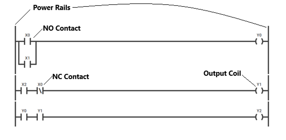
Basic ladder logic symbols form the foundation of PLC programming, representing electrical components in a digital format:
| Symbol | Name | Function |
| -[ ]- | Normally Open Contact | Act like switches that close when energized, allowing power flow through the rung. |
| -[/]- | Normally Closed Contact | Conduct when de-energized and open when energized. |
| -( )- | Output Coil | Act as indicators when the power has reached them |
| -[L]- | Latch | Maintains ON state once energized |
| -[U]- | Unlatch | Releases latched state |
| -[TON]- | On-Delay Timer | Represents a timer that starts counting when its input condition is met. The timer's output is activated after a specified time has elapsed. |
| -[TOF]- | Off-Delay Timer | Represents a timer that starts counting when its input condition is no longer met. The timer's output remains activated for a specified time after the input condition is lost. |
| -[RTO]- | Retentive Timer | Represents a timer that retains its accumulated time when its input condition is lost. The timer's output is activated when the accumulated time reaches a specified value. |
| -[CTU]- | Up Counter | Represents a counter that increments its count each time its input condition is met |
| -[CTD]- | Down Counter | Represents a counter that decrements its count each time its input condition is met. |
Suggested Reading: Ladder Logic Symbols: A Comprehensive Guide
These fundamental components create logic circuits through series and parallel arrangements. The fundamental ladder logic instructions include:
- XIC (Examine If Closed): Tests if bit is ON
- XIO (Examine If Open): Tests if bit is OFF
- OTE (Output Energize): Controls output bit
- OTL (Output Latch): Sets bit ON permanently
- OTU (Output Unlatch): Resets latched bit
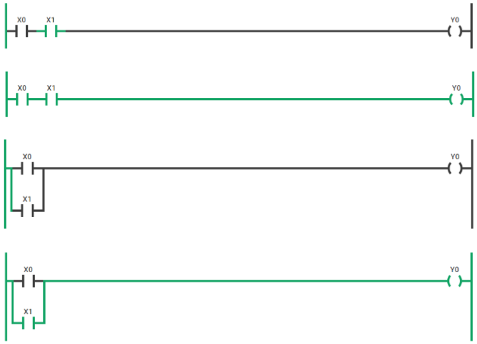
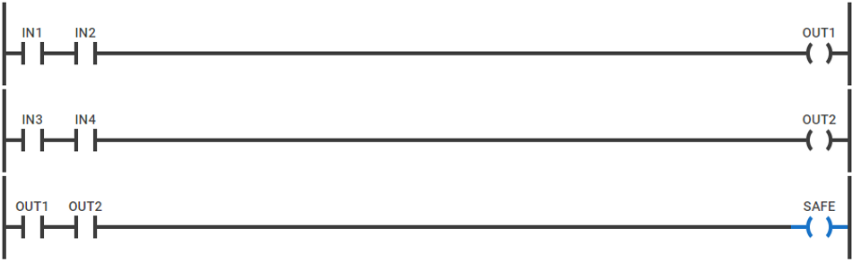
Consider the following basic instruction truth table. The output represents an OR (parallel) and AND (series) output:
Input X0 | Input X1 | Output Y0 (Series) | Output Y0 (Parallel) |
0 | 0 | 0 | 0 |
0 | 1 | 0 | 1 |
1 | 0 | 0 | 1 |
1 | 1 | 1 | 1 |
The ladder logic for both parallel and series outputs is shown below:
Program Structure and Organization
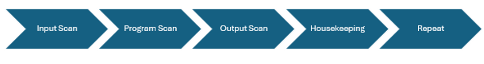
The PLC scan cycle forms the foundation of ladder logic program execution, operating in a continuous sequence:
Memory allocation follows a structured addressing scheme:
Data Table Structure | |
I:0/0-15 Input Image Table I:0/0-15 Input Image Table O:0/0-15 Output Image Table B3:0-255 Bit Storage N7:0-255 Integer Files T4:0-255 Timer Files C5:0-255 Counter Files |
Rung organization adheres to a hierarchical structure:
Main Program
|
├── Subroutine 1
| ├── Rung 0: Input Processing
| ├── Rung 1: Logic Operations
| └── Rung 2: Output Control
|
└── Subroutine 2
├── Rung 0: Safety Interlocks
└── Rung 1: Process Control
Memory addressing utilizes file-based organization:
File Type: Defines data type (B, N, T, C)
File Number: Identifies specific file (3, 7, 4, 5)
Element Number: Specifies location within the file
Bit Number: Indicates specific bit within the element
Program organization best practices:
Input Processing
Dedicate initial rungs to input conditioning
Implement input debouncing
Process safety interlocks first
Logic Processing
Group related operations
Maintain sequential flow
Use comments for complex logic
Output Control
Consolidate output operations
Implement output interlocking
Include fault handling
Subroutine Structure
Limit subroutine size (max 100 rungs)
Use meaningful names
Document purpose and parameters
Memory allocation guidelines:
Reserve 20% memory for program expansion
Group-related data in consecutive addresses
Maintain consistent addressing conventions
Document memory map changes
Performance Optimization Guidelines
Use immediate I/O instructions sparingly (high CPU impact)
Implement message instructions in separate tasks
Limit nested timer operations
Group mathematical operations
Use indexed addressing for array operations
Data Handling and Memory Management
PLC Data Types and Memory Structure:
Data Type | Size (Bits) | Range | Usage |
BOOL | 1 | 0-1 | Discrete I/O |
INT | 16 | -32,768 to 32,767 | General calculations |
DINT | 32 | -2^31 to 2^31-1 | Large numbers |
REAL | 32 | ±1.18e-38 to ±3.4e38 | Floating point |
STRING | 8/char | 82 chars max | Text data |
Memory Addressing Architecture:
Memory Organization
Global Memory
├── Input Image Table (I:x)
├── Output Image Table (O:x)
├── Status File (S:x)
├── Bit Storage (B:x)
├── Timer File (T:x)
├── Counter File (C:x)
└── Control File (R:x)
Data Organization Methods:
Method | Application | Advantages |
Sequential | Related data blocks | Easy maintenance |
Indexed | Array operations | Efficient access |
Structured | Complex data types | Organized data |
Distributed | Network sharing | Remote access |
Data Retention Hierarchy:
Volatile Memory (RAM)
Program execution
Temporary storage
Runtime variables
Non-volatile Memory (EEPROM/Flash)
Program storage
Retained values
Configuration data
Data Backup Implementation:
Automatic Backup
SRAM with battery backup
Flash memory storage
Redundant data storage
Manual Backup
Program archive
Data table export
Configuration backup
Memory Optimization Techniques:
Use appropriate data types (SINT vs DINT)
Implement array operations
Utilize indirect addressing
Minimize temporary storage
Implement data compression
Memory Management Best Practices:
Maintain 30% free memory
Regular memory defragmentation
Systematic memory allocation
Regular backup scheduling
Memory usage monitoring
Implementation and Integration
Industrial Standards and Protocols
Key IEC Standards for PLC Programming:
Standard | Scope | Application |
IEC 61131-3 | Programming Languages | Ladder Logic, FBD, ST, IL, SFC |
IEC 61499 | Function Blocks | Distributed Control Systems |
IEC 61508 | Functional Safety | Safety-Related Systems |
IEC 62061 | Machine Safety | Safety Control Systems |
Communication Protocol Specifications:
Layer | Network Protocol |
Enterprise Level | Ethernet/IP |
Control Level | Modbus TCP, ProfiNet |
Device Level | DeviceNet, Profibus |
Sensor Level | AS-Interface, IO-Link |
Protocol Comparison Matrix:
Protocol | Speed | Distance | Nodes | Determinism |
Modbus RTU | 19.2Kbps | 1200m | 32 | Medium |
Profibus DP | 12Mbps | 100m | 126 | High |
EtherNet/IP | 100Mbps | 100m | 1024 | Medium |
EtherCAT | 100Mbps | 100m | 65535 | Very High |
Implementation Requirements:
Hardware Configuration
CPU selection based on program size
I/O module compatibility
Network interface requirements
Memory capacity planning
Network Architecture
Topology selection (Star, Ring, Bus)
Redundancy implementation
Gateway configuration
Address assignment
Safety Programming Requirements:
Category | Requirements | Implementation |
SIL 1 | Basic Protection | Single Channel |
SIL 2 | Enhanced Safety | Redundant Channels |
SIL 3 | High Safety | Triple Modular Redundancy |
SIL 4 | Mission Critical | Quad Redundancy |
Safety Implementation Guidelines:
Dual-channel input processing
Diverse programming techniques
Cross-checking of critical values
Watchdog timer implementation
Emergency stop circuits
Standard Compliance Checklist:
Program Structure
Modular organization
Clear documentation
Version control
Change management
Safety Functions
Risk assessment
Safety circuit design
Validation procedures
Regular testing schedules
Integration with Automation Technologies
Ladder logic programming is often integrated with other automation technologies to create comprehensive control systems for industrial processes. Some of these technologies include:
Human-machine Interface (HMI) - graphical interfaces that allow operators to interact with and monitor the operation of industrial automation systems. Ladder logic programs can be integrated with HMI software to display real-time process data, control equipment, and receive operator inputs.
HMI Programming Interface Components:Component
Function
Data Type
Tags
Process variables
Boolean, Integer, Real
Screens
Operator interface
Graphics, Controls
Alarms
Event monitoring
Status, Triggers
Trends
Data visualization
Historical, Real-time
Supervisory Control and Data Acquisition (SCADA) - used to monitor and control large-scale industrial processes, such as power generation, water treatment, and oil and gas production.
Distributed Control System (DCS) - used to control complex, continuous processes in industries such as chemical, pharmaceutical, and power generation.
Industrial Internet of Things (IIoT) - a network of interconnected industrial devices and systems that collect, analyze, and share data to improve the efficiency and performance of industrial processes. Ladder logic programs can be integrated with IIoT technologies, such as sensors, actuators, and edge computing devices, to enable real-time data collection and analysis, as well as remote monitoring and control.
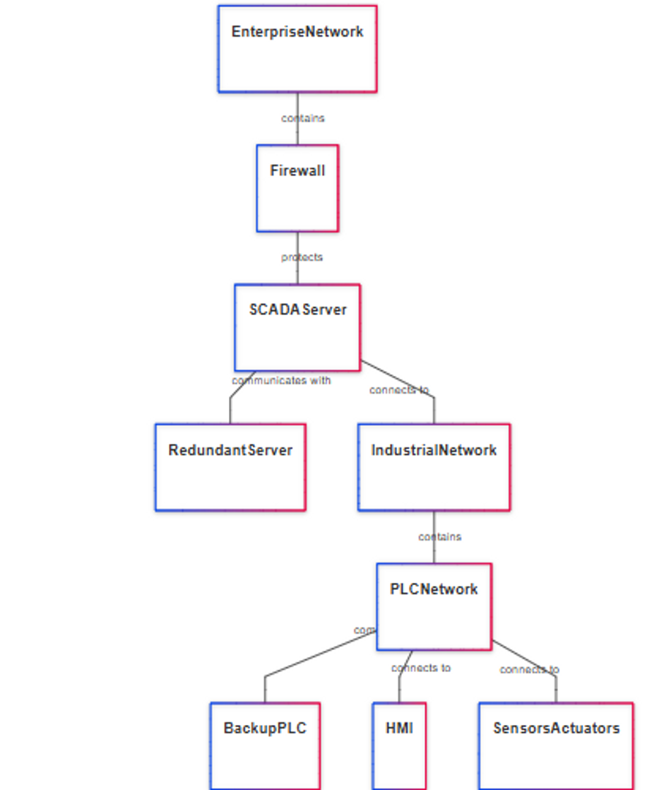
Network Configuration Parameters:
Industrial Ethernet Setup
IP addressing scheme (192.168.1.x)
Subnet masking (255.255.255.0)
Gateway configuration
VLAN segmentation
Data Exchange Protocols
OPC UA for vertical integration
Modbus TCP for device communication
EtherNet/IP for control network
PROFINET for real-time data
Redundancy Implementation:
Controller Redundancy
Hot standby configuration
Synchronous data transfer
Automatic failover
Memory synchronization
Network Redundancy
Dual network paths
Ring topology
Media redundancy protocol
Automatic path selection
Communication Redundancy Matrix:
Level | Primary | Backup | Switchover Time |
Controller | Active PLC | Standby PLC | <100ms |
Network | Main Path | Alternative Path | <20ms |
Server | Primary SCADA | Backup SCADA | <1s |
System Integration Checklist:
Protocol compatibility verification
Address space allocation
Network bandwidth calculation
Response time requirements
Security policy implementation
Troubleshooting and Optimization
Debugging Techniques
Common Programming Errors Matrix:
Error Type | Symptom | Common Cause | Impact |
Logic Error | Unexpected Operation | Incorrect Rung Logic | Process Malfunction |
Timing Error | Race Condition | Improper Sequencing | Intermittent Failure |
Memory Error | Data Corruption | Overflow/Underflow | System Crash |
I/O Error | Signal Mismatch | Wrong Addressing | Field Device Issues |
Debugging Tools and Methods:
Online Monitoring
Real-time value observation
Force table implementation
Trend monitoring
Status bits tracking
Diagnostic Functions
System status monitoring
Error code logging
Execution time tracking
Memory usage analysis
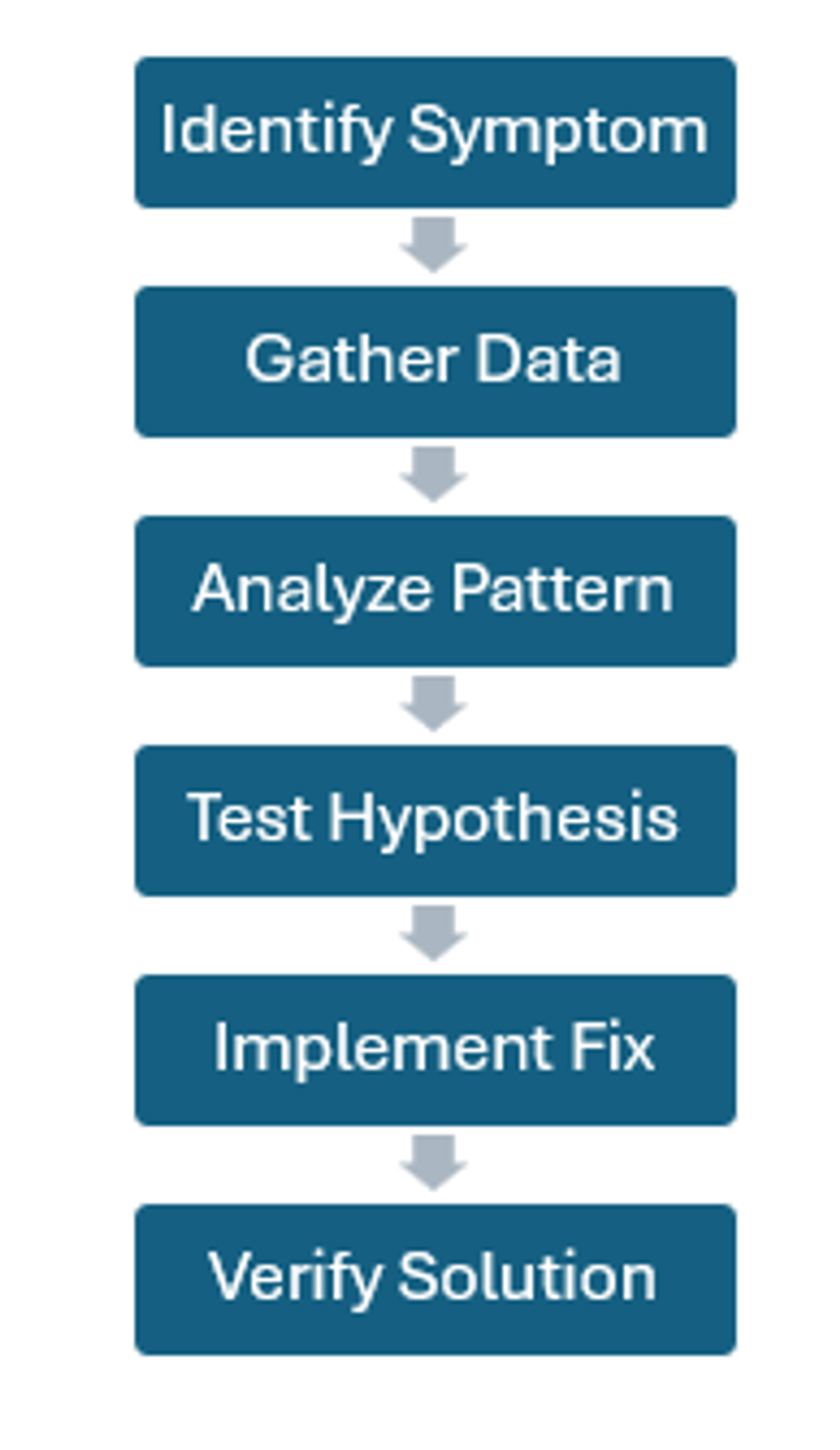
Systematic Debug Process
The debugging process consists of several stages and typically follows the following flow:
Debug Mode Operations:
Function | Purpose | Application |
Single Scan | Step-by-step execution | Logic verification |
Breakpoint | Pause at condition | Sequence check |
Force Value | Override I/O | Hardware simulation |
Trace | Capture data sequence | Timing analysis |
Debugging Best Practices:
Program Structure
Implement error detection rungs
Use status bits for monitoring
Create diagnostic subroutines
Maintain execution logs
Testing Procedures
Systematic input testing
Output verification
Sequence validation
Timer coordination
Documentation Requirements
Error code documentation
Modification tracking
Test case recording
Solution archiving
Performance Optimization
Program Structure Optimization Techniques:
Technique | Impact | CPU Load Reduction |
Subroutine Modularization | High | 15-25% |
Conditional Jump | Medium | 10-15% |
Indexed Addressing | High | 20-30% |
Interrupt Handling | Very High | 25-35% |
Performance Benchmarks:
Execution Metrics
Base Scan Time: 10ms
Optimized Scan: 6ms
I/O Update: 2ms
Background Tasks: 2ms
Memory Utilization
Program Space: 60%
Data Table: 40%
I/O Configuration: 20%
System Overhead: 10%
Resource Management Matrix:
Resource | Allocation | Optimization Method | Impact |
CPU Time | 100% | Task Prioritization | +30% Speed |
Memory | 80% | Data Compression | +40% Space |
I/O Bandwidth | 60% | Scheduled Updates | +25% Throughput |
Network | 50% | Protocol Optimization | +35% Efficiency |
Advanced Optimization Strategies:
Program Execution
Implement immediate I/O updates
Use indexed addressing for arrays
Optimize jump instructions
Minimize redundant operations
Memory Management
Implement data compression
Use appropriate data types
Optimize string handling
Manage temporary storage
Task Scheduling
Prioritize critical tasks
Balance load distribution
Optimize interrupt handling
Implement background processing
Resource Utilization Guidelines:
Maximum CPU load: 80%
Memory utilization: 75%
I/O scan frequency: Based on process
Network bandwidth: 60% maximum
Performance Monitoring Metrics:
Metric | Target | Warning | Critical |
Scan Time | <10ms | 10-15ms | >15ms |
Memory Use | <75% | 75-85% | >85% |
I/O Response | <5ms | 5-10ms | >10ms |
Task Queue | <5 | 5-10 | >10 |
Ladder Logic Applications in Industrial Automation
Ladder logic programming is widely used in industrial automation due to its intuitive nature, ease of implementation, and compatibility with various programmable logic controllers (PLCs). Some common applications of ladder logic programming in industrial automation include:
Motor Control - Ladder logic programs are often used to control the operation of motors in various industrial processes. This can involve starting and stopping motors, controlling their speed and direction, and implementing safety features such as overload protection and emergency stops.
Conveyor Systems - In manufacturing and material handling, ladder logic programs are used to control conveyor systems. This can include controlling the movement of products along the conveyor, coordinating the operation of multiple conveyors, and implementing safety features such as interlocks and emergency stops.
Batch Processing - Ladder logic programs can be used to control batch processes in industries such as chemical, pharmaceutical, and food processing. This involves coordinating the operation of various equipment, such as pumps, valves, and mixers, to ensure that the process is carried out according to predefined recipes and schedules.
Assembly Lines - In automotive and electronics manufacturing, ladder logic programs are used to control assembly lines. This can involve coordinating the operation of robots, pick-and-place machines, and other equipment to ensure that products are assembled accurately and efficiently.
Packaging and Palletizing - Ladder logic programs are used to control packaging and palletizing systems in various industries. This can involve coordinating the operation of equipment such as cartoners, case packers, and palletizers to ensure that products are packaged and palletized according to predefined specifications.

Conclusion
Ladder logic programming remains fundamental to industrial automation, with standardization driving reliability and maintainability. The implementation of structured programming methodologies, combined with proper documentation and testing procedures, ensures robust control systems.
Frequently Asked Questions
1. How do you implement redundant safety circuits in ladder logic?
A: Safety circuits require dual-channel implementation:
2. What causes excessive PLC scan times?
A: Common factors include:
Complex mathematical operations
Inefficient program structure
Excessive immediate I/O operations
Unoptimized communication protocols Resolution: Implement task scheduling and program optimization techniques.
3. What are the limitations of ladder logic programming?
A: Ladder logic programming has some limitations, such as limited support for complex data structures and algorithms, and a primarily graphical programming interface that may not be as intuitive for some users as text-based programming languages. However, its simplicity and widespread adoption in industrial automation make it a valuable skill for control system engineers and technicians.
4. How do you manage large program modifications?
A: Implementation strategy:
Version control system
Offline testing environment
Staged implementation
Rollback procedures
Documentation updates
5. What are effective debugging strategies for intermittent faults?
A: Systematic approach:
Implement trace functions
Use trigger conditions
Monitor state transitions
Log timing sequences