What is PLC? An Integral Component of Industrial Automation
How PLC controls production systems and processes in harsh industrial environments

Last updated on 13 Sep, 2021. 7 minutes read
What is a PLC? Understanding the Basics
PLC, which stand for Programmable logic controllers are industrial-scale devices with computing capabilities, which are used to control production processes in the context of assembly lines, robotic cells, industrial machinery, and other manufacturing settings [1]. They are used in processes like fault detection, high reliability, and programmable manufacturing control. PLCs operate in real-time as their inputs must be processed in very short timescales. The timeliness of their operation is always critical for successfully fulfilling their control purpose. The primary motivation behind the introduction of PLCs several decades ago was to replace hard-coded relay systems with more flexible programmable controllers. PLCs were first deployed in automotive production lines to provide increased automation and reliability in the control of industrial processes.
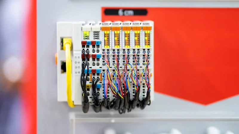
PLCs do not look like conventional computers, as they have undergone a ruggedizing process in order to be hard-wearing and shock-resistant. There are various types of PLC, which vary in the number and type of their I/Os (Inputs/Outputs), their housing and packaging, as well as their capabilities to interact with other PLCs and SCADA systems. These properties of PLCs determine their ability to operate in harsh industrial environments in ways that resist high temperatures and vibration while being immune to electric noise.
The most common functionality of a PLC controller is similar to that of an electromechanical relay. Specifically, a PLC receives a set of discrete inputs and audits whether the input state is on or off. The operation is based on a “scan cycle”, which reads the PLC inputs, executes the programmable logic, and writes its outputs. In the scope of a PLC’s operation, these three steps are continually repeated as scan cycles are executed repeatedly.
PLC programs implement a logical “AND” function over a series of inputs. Current is allowed to pass when all input bits are on. Likewise, they also implement a logical “OR” function over a set of inputs that are provided in parallel. In this case, current is allowed to pass if at least one input is on. In implementing these functions, PLCs apply a certain order in the evaluation of the logic functions. It is a strictly left-to-right and top-to-bottom execution, which is contrary to the less strict operation of legacy relays. There are also PLCs that implement more sophisticated functions (e.g., internal discrete logic functions) towards producing outputs that signal completion or some error.
End-users (e.g., automation engineers) interact with PLCs to configure them, but also to receive alarms and notifications. To this end, PLCs provide human-machine interfaces (HMIs), including Graphical User Interfaces (GUIs). Common HMI controls include buttons, lights, textual displays, and touch screens. In the case of sophisticated installations, the PLC can connect to a Personal Computer, which provides more sophisticated and more ergonomic user interfaces.
Components of PLC
A PLC consists of the following main components:
- Power supply: It powers the various components of a PLC with DC voltage. To this end, the power supply converts the user’s line AC voltage (e.g., 120 volts in the US) to a lower DC voltage (e.g., 24 volts).
- Processor: This is a solid-state device that implements industrial control functions in a manufacturing setting (e.g., production line, machine tool, robotics device), as well as other process control functions.
- Input/Output (I/O): A PLC comprises various input and output modules. Input modules detect the state of input signals from various sources like push-buttons, switches, and various sensors. On the other hand, output modules are destined to control devices such as relays and lights.
- Communication Modules and Protocols: A PLC’s communication modules facilitate the transfer of digital data between the PLCs and other devices of the industrial site. To enable this transfer, the communication modules implement one or more protocols, including both wireline and wireless protocols. A non-exhaustive list of industrial protocols used by PLCs includes EtherNet/IP, Profibus, Modbus, Interbus, ProfiNet, and more. PLC communication takes place through built-in ports on the device such as USB (Universal Serial Bus), Ethernet, RS-232, RS-485, and RS-422 ports. Using these ports PLCs communicate with software systems, external devices (e.g., sensors, actuators), as well as other control systems like SCADA.
- Redundancy: Non-trivial industrial grade PLC installations offer some sort of redundancy. Specifically, they comprise a shadow PLC system that is destined to replace a primary system in cases where the primary system goes out of order. To detect cases when the redundant system must be activated, PLCs implement a heartbeats mechanism.
- PLC Programs: A key element of a PLC device is its control logic, which is programmed and reflected in specialized languages for industrial automation and electrical systems like Ladder Diagrams and Function Block Diagrams.
PLC Programming - Ladder Logic and Ladder Diagram
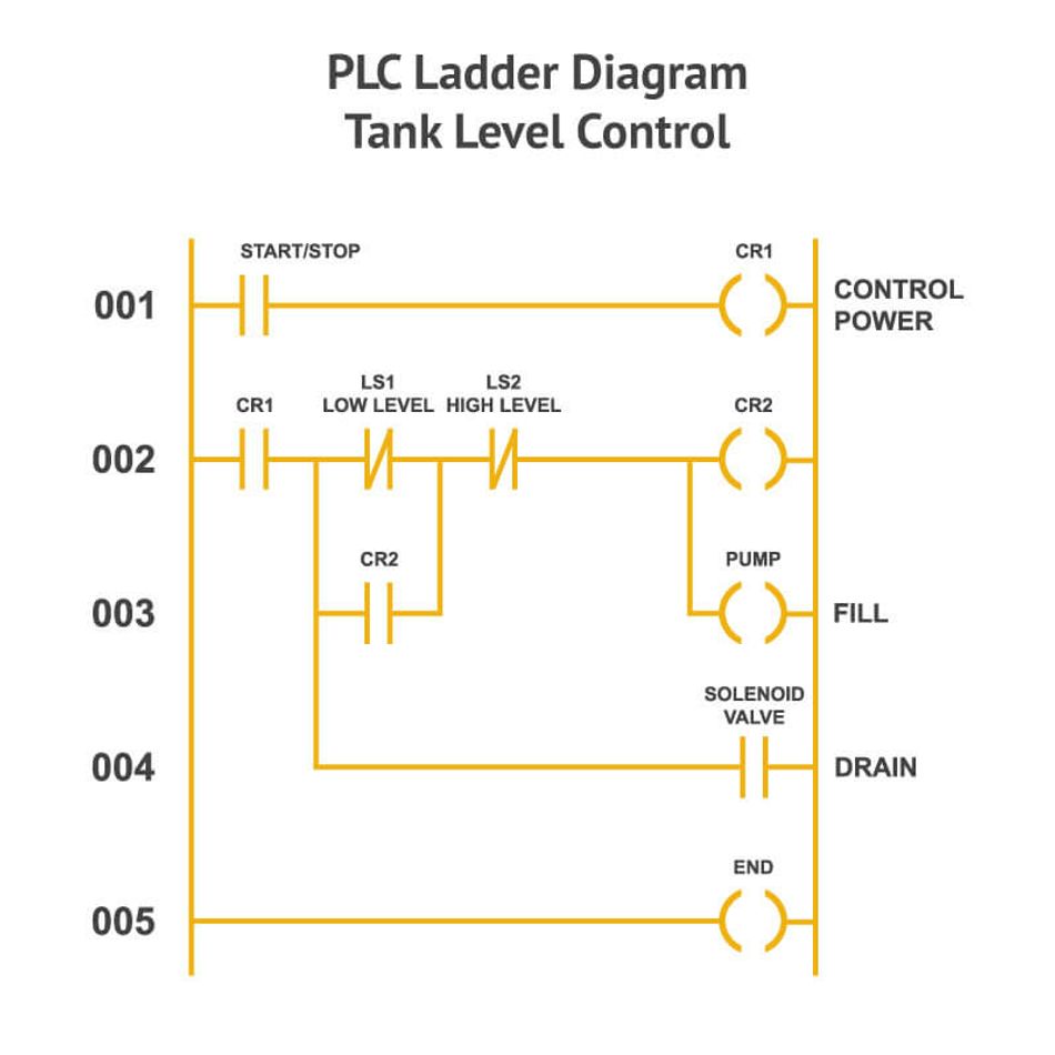
PLCs logic can be programmed in different languages, including high-level visual programming languages. One of the most popular visual programming languages for PLC control logic and configuration is Ladder Logic (LL), which is reflected on the ladder diagram (LD)[2]. Ladder Logic's main benefit is that it offers a visual interface, which significantly reduces the PLC programming learning curve. Furthermore, Ladder Logic and Ladder Diagrams are structured like electrical relay circuits, which makes it very easy for electromechanical engineers and industrial engineers to understand and use them. Likewise, familiarity with bit operators and Boolean logic facilitates understanding and using Ladder Logic.
From a programming perspective, Ladder Logic expresses logic operations using symbolic notation. Hence, a Ladder Logic program comprises batches of mathematical logic in a symbolic location i.e., based on bit logic operation, which is structured like a ladder. That’s the reason and rationale behind the name “Ladder Logic”. The exact structure of Ladder Logic is dictated by the PLCOpen standard, which makes it a standardized programming language. However, Ladder Logic was not invented for conventional programmers of high-level programming languages. Rather it was primarily designed for technicians, electricians, and electrical engineers that are familiar with electric signals. Therefore, Ladder Logic symbols look like electric signals such as contacts and relays. These symbols map to Boolean and symbolic logic in the context of a Ladder Logic program.
Ladder Logic is the most popular PLC programming language, yet it is not the only way to program PLC. Other popular languages include Sequential Function Charts (SFC), Function Block Diagram (FBD), Structured Text (ST), and Instruction List (IL). These languages have conceptual and syntactical similarities to Ladder Logic while having a smooth learning curve for engineers and technicians that are familiar with electric concepts.
PLC Applications: Selecting a PLC for your Industrial Application
Given the variety of available PLCs, industrial engineers have to go through a process of evaluating different devices towards selecting the best one for their tasks. To this end, they must review the requirements of their system and of the application where the PLC will be used. Likewise, information and requirements about the I/O capacity of the PLC must be collected, while the type of targeted outputs must be clarified. For instance, the electrical requirements of I/O modules must be documented, including input device voltage, output device voltage, and current. It is also important to identify whether the PLC should support special operations and advanced functions beyond simple discrete (On/off) logic.
Another important aspect for the selection of a PLC relates to the memory and CPU (Central Processing Unit) of the PLC device. To determine CPU requirements, it is important to understand the speed of the industrial process or machine to be controlled. This involves identifying the fastest action needed, as well as the time criticality and the response time of the various operations. It is also necessary to factor in the communication requirements in the PLC selection process. Specifically, data sharing needs must be identified, along with the devices (e.g., computer, touch screen in a workstation) that must communicate with the PLC. In this way, any required communication devices (e.g., modems, cables) can be identified as well.
The PLC selection process must also factor in the need for interacting with the operator via some interfaces like push buttons or LED (Light Emitting Diode) numeric displays. Specifically, the selected PLC must provide support for displaying the proper messages to the operator, along with any required alarms and notifications. Likewise, the operator should be provided with the means to input data in line with the needs of the application.
The PLC selection process must also consider the physical environment where the automation device will be deployed. This is important for employing devices that have undergone proper ruggedization i.e., devices strong and resistant to shocks as imposed by the target environment at hand.
Finally, there are also non-technical criteria that determine the selection decision, including the cost of the device and the quality of complementary services provided like training and post-sales support. The various criteria must be weighed against their relevant importance for the application at hand. This will drive the selection of products with proper modules, value-added programmability features, operator interfaces, and costs.
Overall, PLCs are among the most popular devices used in industrial control applications. They are also expected to remain at the heart of industrial control in the era of the fourth industrial revolution (Industry 4.0) [3]. However, the emerging Industry 4.0 applications will provide the means for driving the operation of PLCs in intelligent and data-driven ways. Specifically, PLCs operation in the Industry 4.0 will be driven not only by sensors and Cyber Physical devices but also by data analytics on the cloud. This holds the promise to improve the accuracy and intelligence of next-generation industrial automation systems. In this context, it makes perfect sense for younger engineers to learn more about PLCs and their operations.
References
- K. T. Erickson, "Programmable logic controllers," in IEEE Potentials, vol. 15, no. 1, pp. 14-17, Feb. March 1996, doi: 10.1109/45.481370.
- M. C. Zhou and E. Twiss, "Design of industrial automated systems via relay ladder logic programming and Petri nets," in IEEE Transactions on Systems, Man, and Cybernetics, Part C (Applications and Reviews), vol. 28, no. 1, pp. 137-150, Feb. 1998, doi: 10.1109/5326.661096.
- M. Azarmipour, H. Elfaham, C. Gries and U. Epple, "PLC 4.0: A Control System for Industry 4.0," IECON 2019 - 45th Annual Conference of the IEEE Industrial Electronics Society, 2019, pp. 5513-5518, doi: 10.1109/IECON.2019.8927026.