Ladder Logic Symbols: A Comprehensive Guide
Decoding the Essentials: A Detailed Overview of Ladder Logic Symbols in Automation

Last updated on 16 Nov, 2023. 13 minutes read

Ladder logic symbols, or bit logic instructions, are the basis of ladder diagram programming, a graphical language widely used in industrial control systems. Ladder logic symbols are comparable to the vocabulary of this language, representing various logical operations, inputs, outputs, and other control system components. Understanding ladder logic symbols is crucial for anyone programming or maintaining these systems, as they visually represent the control logic. This article will explain ladder logic symbols' complexities, usage, and role in creating effective control systems.
Understanding Ladder Logic Symbols
Before Programmable Logic Controllers (PLC), manufacturing plants employed relay-based electric circuits to energize different loads; however, relays were costly and troublesome, so a new solution was developed. Ladder logic symbols were invented as a programming language for PLCs, using graphical diagrams based on relay logic hardware to keep the similarity of the old system. Similarly to computers, PLCs operate with binary signals, each can be set to zero or one (false or true), called a boolean data type.
The language was developed to make PLC programming more accessible to electricians and maintenance engineers, who were more familiar with hardware relay logic diagrams. This allows for creating complex yet efficient control systems that can be easily modified and maintained. Moreover, ladder logic offers a user-friendly interface that mimics physical relay logic, which is excellent for those new to programming.
The basic principles of ladder logic are straightforward. Each rung on the ladder defines one operation in the control process. A rung has read rails on the left, write rails on the right, and the logic operations in between. The logic flow is from left to right, with the condition of the output determined by the state of the inputs.
Recommended Reading: What is a PLC (Programmable Logic Controllers): A Comprehensive Guide
Importance of Ladder Logic Symbols in Industrial Automation

In industrial automation, ladder logic is the dominant language used to program PLCs, the pillars of modern industrial control systems. PLCs control various applications, from simple lighting functions to entire production lines.
For instance, in an automotive assembly line, PLCs control the conveyor belt operation, the robotic arms, the sensors that detect the presence of the car body, and many other elements. The ladder logic program coordinates these operations, ensuring each assembly process step happens at the right time and in order.
One of the reasons ladder logic is so popular among engineers and technicians is its simplicity and visual nature. They can often understand and troubleshoot a ladder logic program by looking at the diagram. This user-friendly interface, combined with the powerful capabilities of modern PLCs, has established the role of PLC ladder logic in industrial automation.
Recommended Reading: What is PLC? An Integral Component of Industrial Automation
Basics of Ladder Logic Symbols
Ladder logic symbols represent various components and operations in a control system, such as inputs, outputs, logical operations, timers, counters, and more. Each symbol has a specific meaning and function in the ladder diagram.
The standard ladder logic symbols are based on the electrical diagram symbols used in relay logic. This makes ladder logic a more intuitive language for those with an electrical engineering or maintenance background. However, modern ladder logic includes many symbols that have no direct equivalent in relay logic, reflecting the increased capabilities of PLCs.
Common Ladder Logic Symbols
The contact and coil symbols are the most commonly used ladder logic symbols. These symbols represent a control system's primary inputs and outputs and form the core of most ladder logic programs.
Contact Symbols
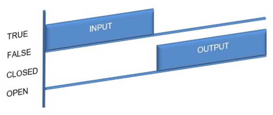
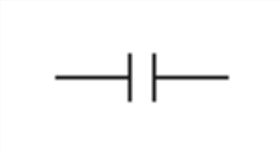
Contact symbols represent the state of an input or output. They come in two main types: normally open (NO) and normally closed (NC). A normally open contact allows current to flow (i.e., it is 'closed') when its associated condition is true. Conversely, a normally closed contact allows current to flow (i.e., it is 'closed') when its associated condition is false.
In a ladder diagram, a NO contact is drawn as a pair of parallel lines, similar to an open switch in an electrical diagram. When the condition associated with the contact is true, the contact closes, allowing the current to flow to the right.
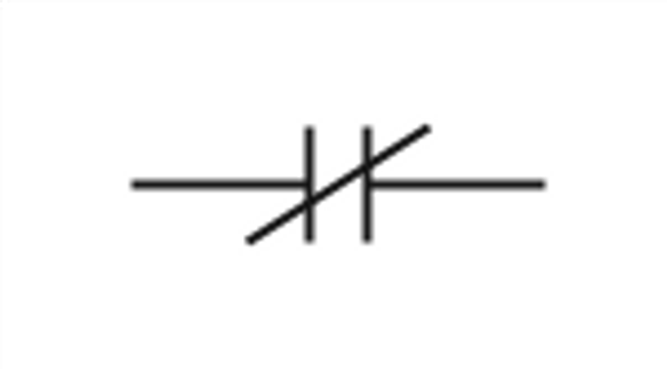
An NC contact, on the other hand, is drawn as a pair of parallel lines with a diagonal line across them, similar to a closed switch in an electrical diagram. When the condition associated with the contact is false, the contact opens, preventing the current from flowing to the right.
Image credit: Ladder Logic World.
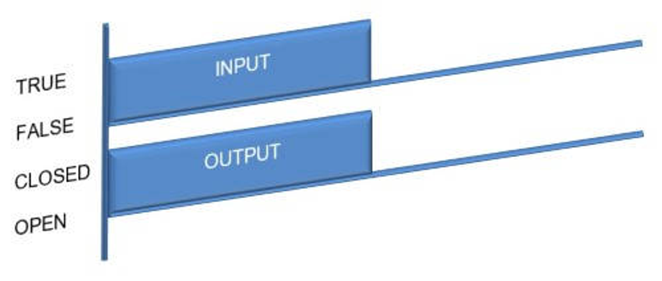
Image credit: Ladder Logic World.
Coil Symbols
Coil symbols represent outputs in a ladder logic diagram. There are three main types of coil symbols: output coil, set coil, and reset coil.
An output coil controls a device or condition in the control system. Current flows to an output coil and activates the associated device or condition. In a ladder diagram, an output coil is drawn as a circle or a rectangle.
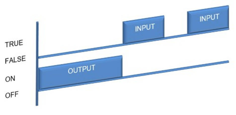
A set coil and a reset coil are used together to control a device or condition that can be turned on and off. The set coil turns on the device or condition when current flows to it, and it stays ON even if the condition goes false. On the other hand, the reset coil turns off the device or condition when current flows to it, and if the input condition is false, it has no effect on the output. In a ladder diagram, a set coil is drawn as a circle or a rectangle with an 'S' inside it, and a reset coil is drawn as a circle or a rectangle with an 'R' inside it.
Image credit: Ladder Logic World.

Image credit: Ladder Logic World.
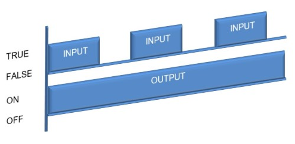
Image credit: Ladder Logic World.
Special Ladder Logic Symbols
Beyond the basic contact and coil symbols, ladder logic includes a variety of special symbols that represent more complex operations and components. These symbols allow ladder logic programs to perform advanced functions such as timing, counting, arithmetic operations, and comparisons.
Timer and Counter Symbols
Timer and counter symbols control operations that depend on time or the occurrence of certain events. A timer symbol represents a delay, either ON or OFF, or a period, and is usually presented as a box with the letter 'T' and a number that represents the time delay. For the timer delay ON, if the input condition is true, then the timer begins, and when the preset time set point has been reached, the output turns on. If the input condition goes false at any stage, the timer stops, and the output turns off.
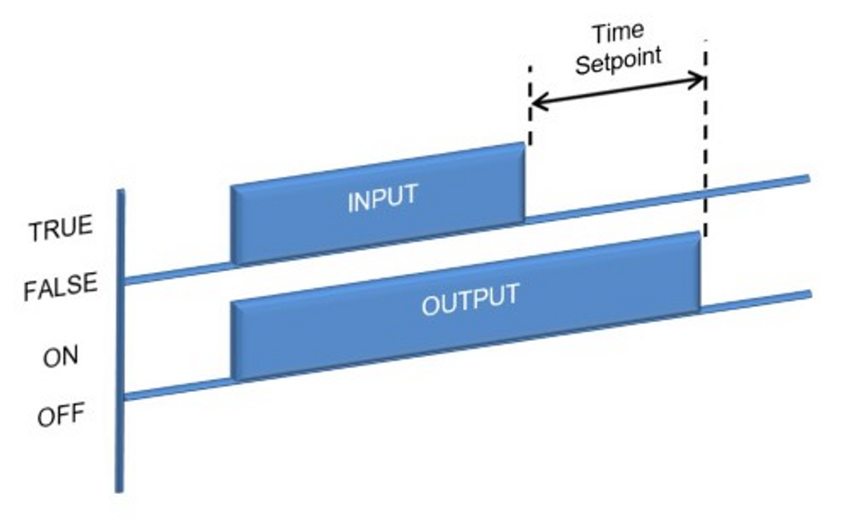
On the other hand, for the timer delay off, if the input condition is true, the output turns on, and if the input condition goes false, the timer begins. When the preset time set point has been reached, the output turns off, but if the input condition goes true at any stage, the timer stops, and the output turns on.
A counter symbol can be either UP or DOWN and is usually presented as a box with the letter 'C' and a number that represents the count. If the input condition transitions from false to true, the counter is incremented by 1 for the counter UP. The output is true when the count value reaches the preset value. The counter is set back to 0 by triggering the reset input.
On the other hand, if the input condition transitions from false to true for the counter DOWN, then the counter is decremented by 1. When the count value reaches zero, the output is set to true. The counter is set back to the preset value by triggering the reset input.
Image credit: Ladder Logic World.
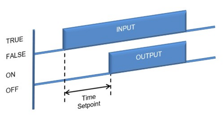
Image credit: Ladder Logic World.
Arithmetic and Comparison Symbols
Arithmetic and comparison symbols allow a ladder logic program to perform mathematical operations and make decisions based on the results of comparisons. Arithmetic symbols represent addition, subtraction, multiplication, and division operations. They are usually drawn as boxes with the symbols '+,' '-,' '*,' and '/,' or written "add," "sub," "mul," and "div."
Comparison symbols represent operations such as greater than, less than, equal to, not equal to, greater than or equal to, and less than or equal to. They are usually drawn as boxes with the symbols '>,' '<, ''=,''≠, ''≥,' or '≤. ' These symbols allow a ladder logic program to compare two values and make decisions based on the comparison result. For example, a comparison symbol could be used to activate an output when the temperature measured by a sensor exceeds a specific value.
The following table summarizes the ladder logic symbols, names, and functions.
Symbol | Name | Function |
 | Normally Open Contact (NO) | If the condition is true, then the output is enabled. If the condition is false, then the output is disabled. |
 | Normally Closed Contact (NC) | If the condition is true, then the output is disabled. If the condition is false, then the output is enabled. |
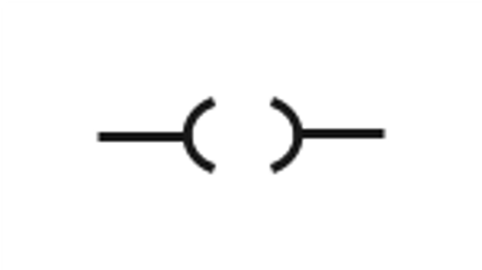 | Output Coil | If the condition is true, then the output is ON. |
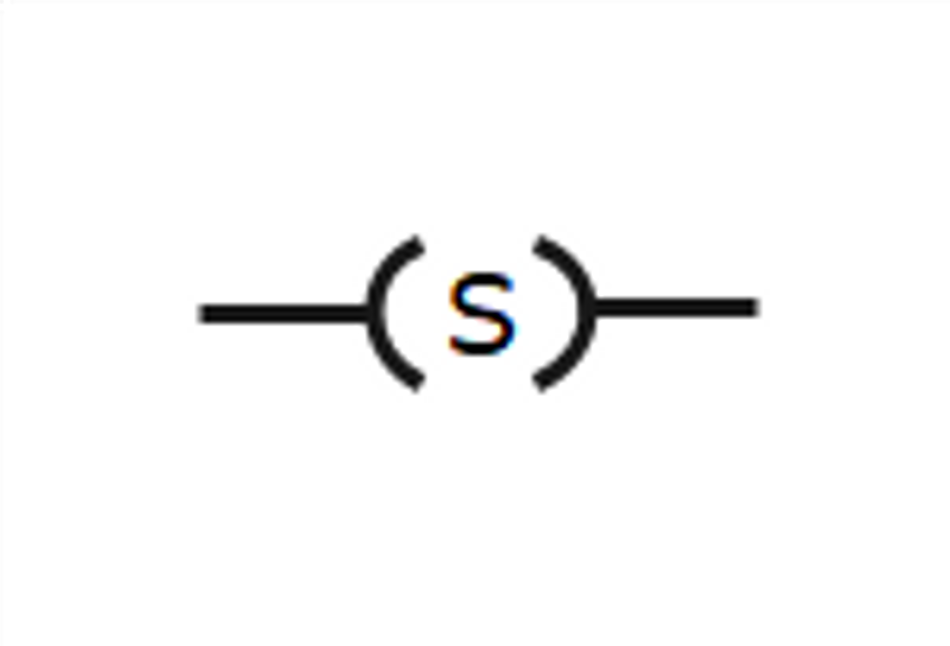 | Set Coil | If the condition transitions from false to true, then the output is ON, and once it is set ON, it stays ON even if the condition goes false. |
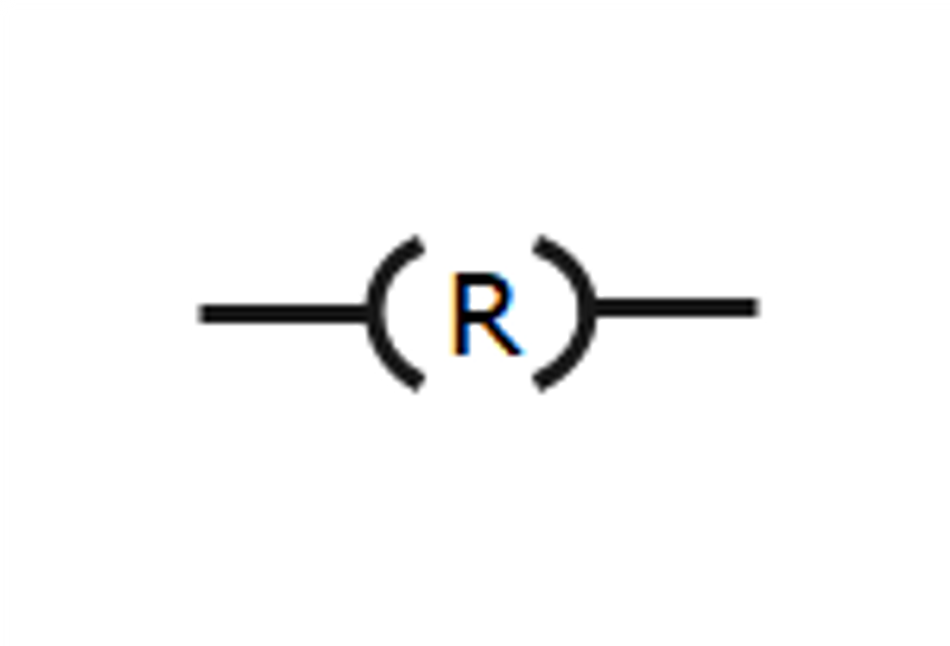 | Reset Coil | If the condition is true, then the output is reset to OFF. If the input condition is false, it does not affect the output.
|
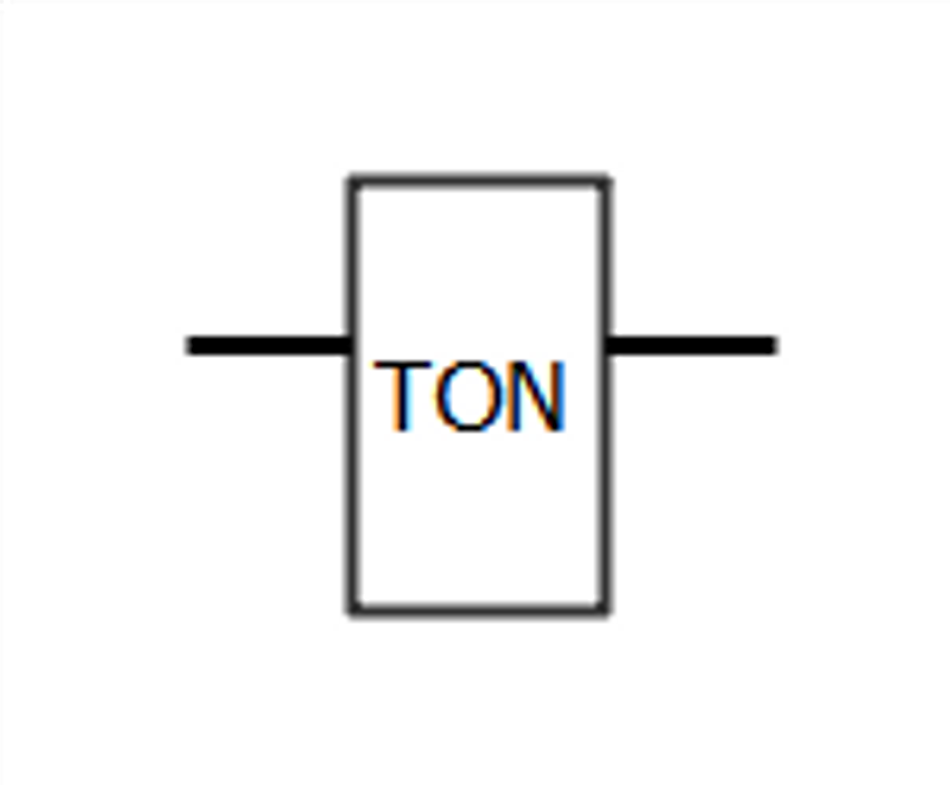 | Timer Delay ON | If the condition is true, the timer begins, and when the present time set point has been reached, the output turns ON. If the condition is false, at any stage, the timer stops, and the output turns OFF as well. |
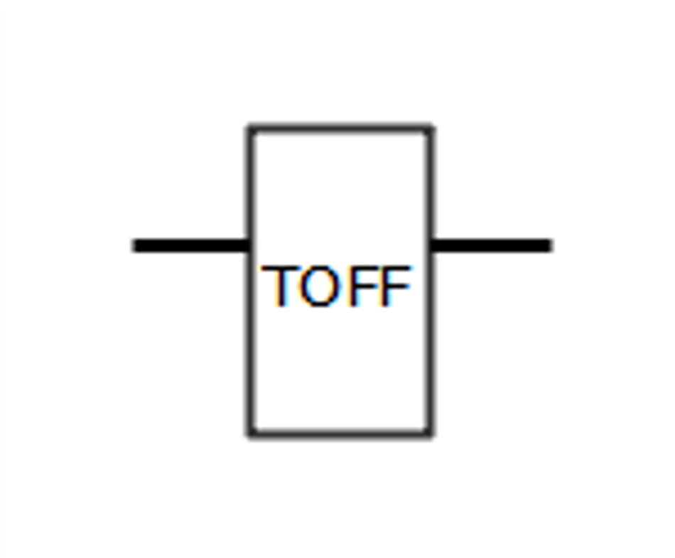 | Timer Delay off | If the condition is true, then the output turns ON. Then, if the input condition goes false, the timer begins, and when the preset time set point has been reached, the output turns OFF. If the condition goes true at any stage, the timer stops, and the output turns ON. |
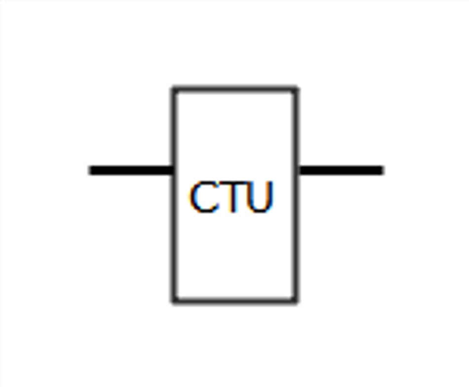 | Counter Up | If the condition transitions from false to true, the counter increases 1 value from the last stored value. If this stored value reaches the preset value, the output will go true, and the stored value is set again to 0. |
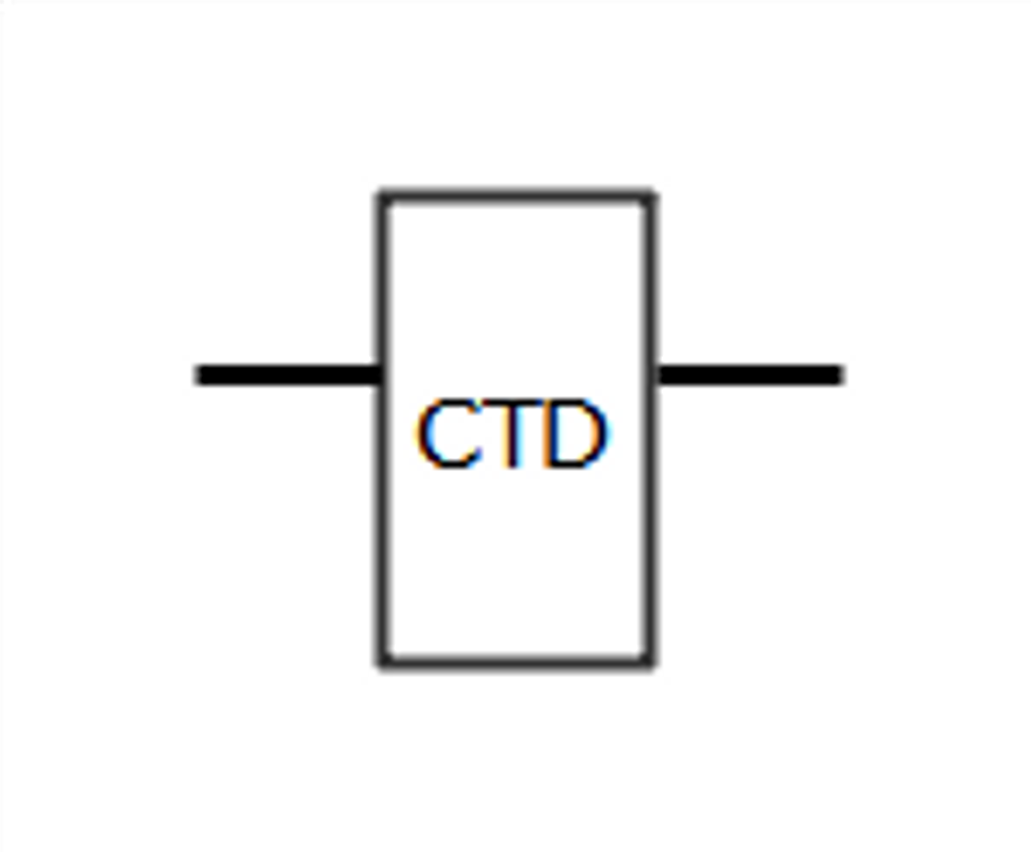 | Counter Down | If the condition transitions from false to true, the counter decreases 1 value from the last stored value. If this stored value reaches 0, the output will go true, and the stored value is set again to the preset value. |
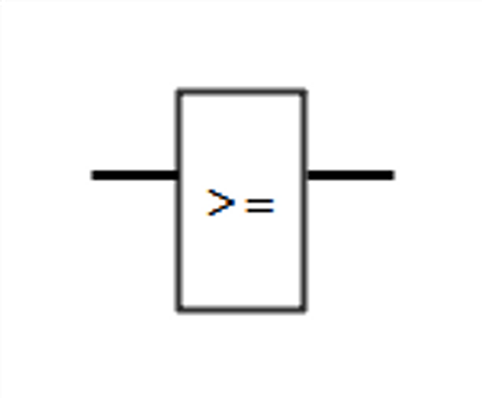 | Greater than or equal to | If the two inputs comparison is true, then the output is true. Otherwise, it is false. |
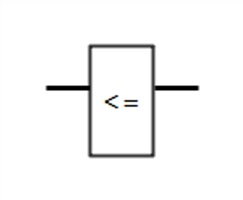 | Less than or equal to | If the two inputs comparison is true, then the output is true. Otherwise, it is false. |
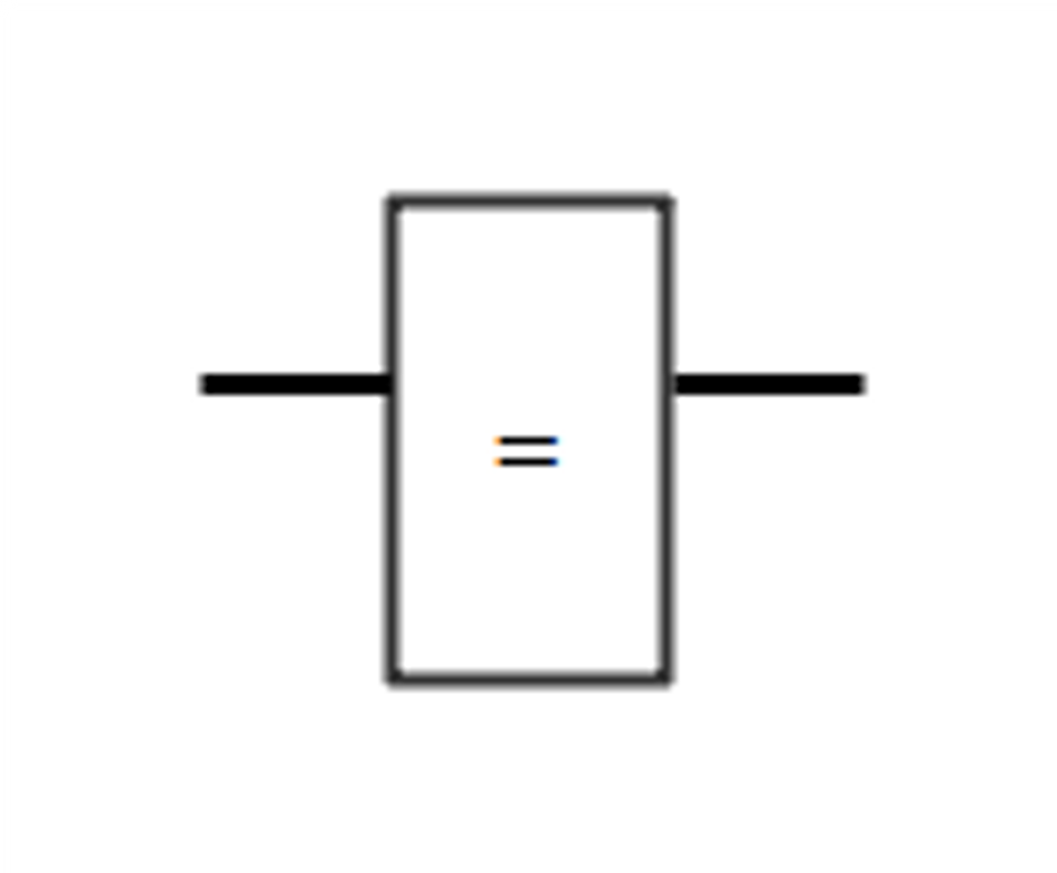 | Equal to | f two inputs are equal, then the output is true. |
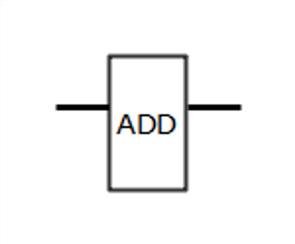 | Addition | Adds one value to the other one. |
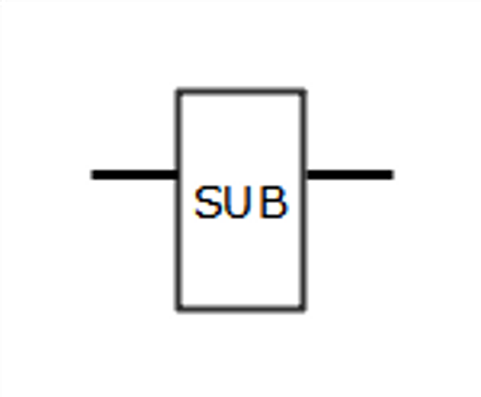 | Subtraction | Subtracts one value from the other one. |
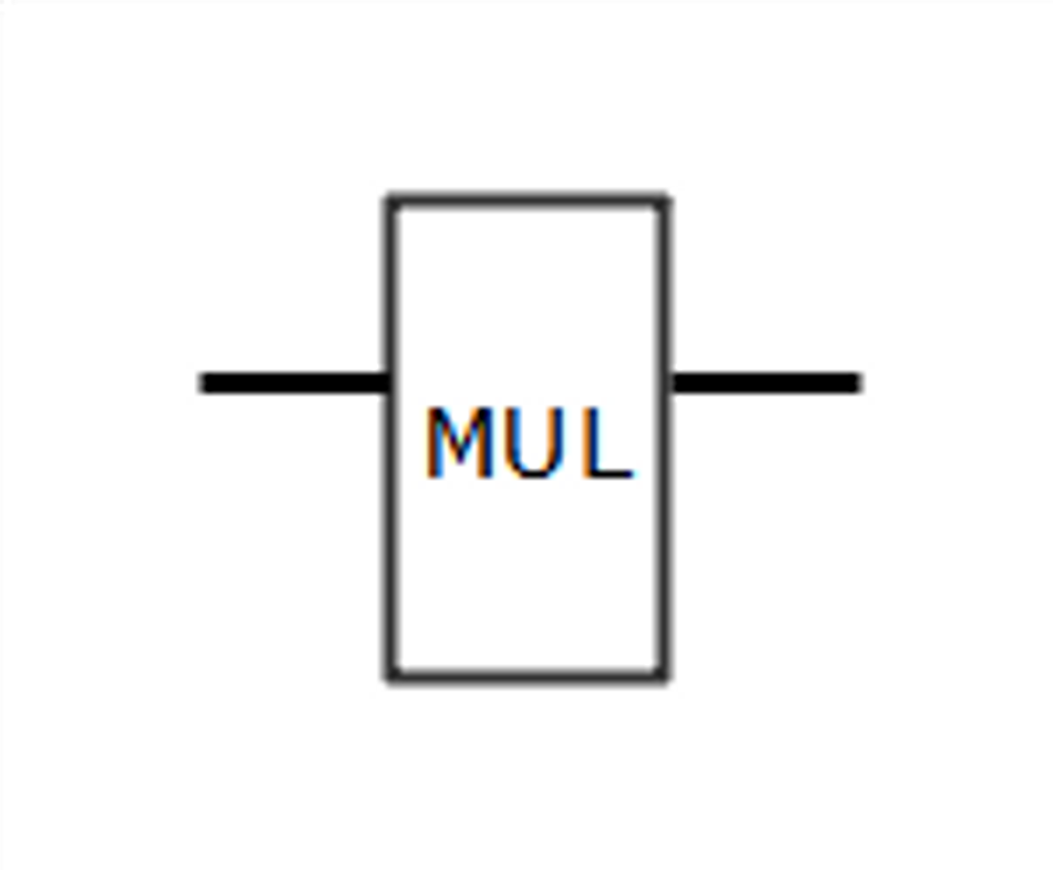 | Multiplication | Multiply two values. |
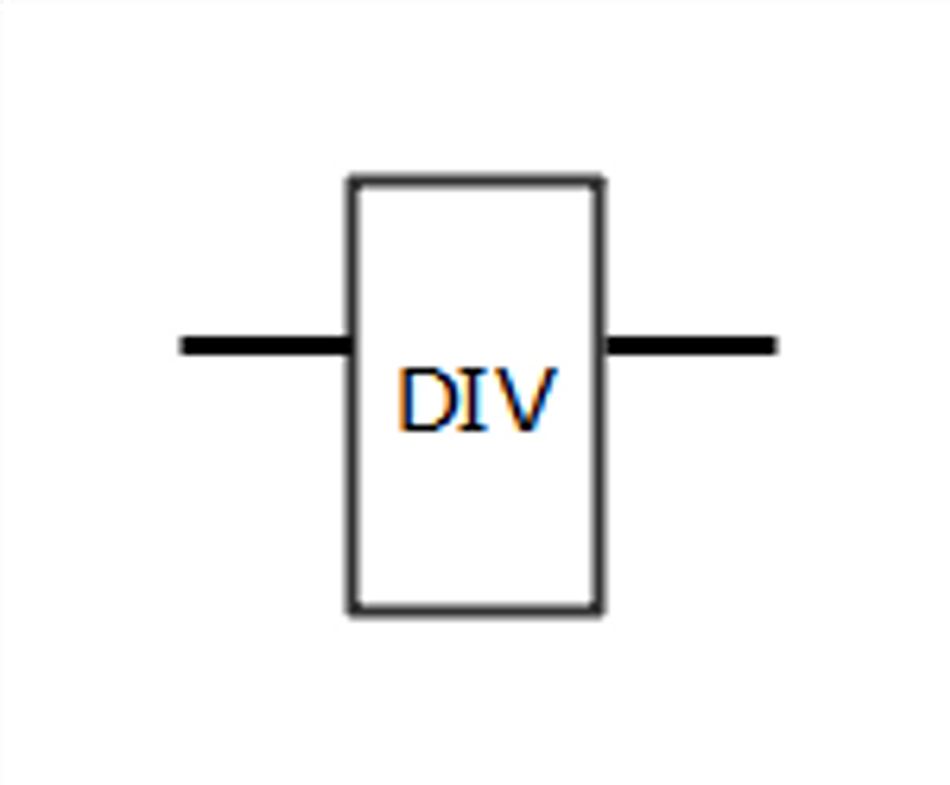 | Division | Divide two values. |
Recommended Reading: Exploring Ladder Logic Programming: An In-depth Exploration
Reading Ladder Logic Diagrams
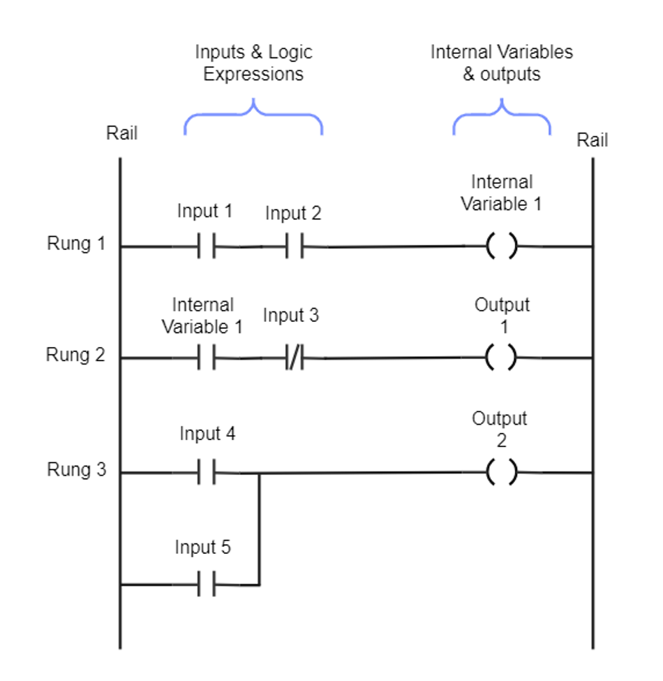
Image credit: EdrawMax Community.
Understanding Rungs and Rails
In a ladder logic diagram, the vertical lines on either side are called rails, while the horizontal lines connecting the rails are called rungs. The left rail is typically associated with the power source, while the right rail represents the ground or neutral connection. The rungs contain the ladder logic symbols that define the system's control logic. Each rung represents a single operation or condition in the control process. The logic flows from left to right, with the output state determined by the state of the inputs and the logic symbols on the rung.
Interpreting Symbol Arrangements
The arrangement of ladder logic symbols on a rung determines the function and behavior of that rung within the control system. One typical arrangement is the series connection of NO contacts. In this configuration, all the contacts must be closed (i.e., their associated conditions must be true) to energize the output coil. This arrangement represents a logical AND operation, as all the input conditions must be met for the output to be activated.
Another typical arrangement is the parallel connection of NO contacts. In this configuration, the output coil will be energized if any contacts are closed (i.e., their associated conditions are true). This arrangement represents a logical OR operation, as any of the input conditions being met will activate the output. In more complex ladder logic diagrams, combinations of series and parallel connections can be used to create intricate control logic.
Creating Ladder Logic Diagrams
Planning a Ladder Logic Diagram
As a ladder programmer, before diving into creating a ladder logic diagram, it is essential to plan the control system thoroughly. This planning stage involves understanding the system's requirements, identifying inputs and outputs, and determining the logical operations needed to achieve the desired behavior.
A well-planned ladder logic diagram will be more straightforward to develop, troubleshoot, and maintain. Some tips for effective planning include:
Clearly define the objectives and requirements of the control system.
Identify all the inputs and outputs, and determine their relationships to each other.
Break down the control logic into smaller, manageable tasks or operations.
Consider potential issues or limitations that may arise during implementation and operation.
Implementing Ladder Logic Symbols
Once the planning stage is complete, the next step is implementing the ladder logic symbols in the diagram. This involves placing the appropriate symbols on the rungs and arranging them to represent the control logic accurately.
When implementing ladder logic symbols, keep the following guidelines in mind:
Start by placing the input symbols on the left side of the rungs. These symbols represent the conditions that must be met for the output to be activated.
Arrange the input symbols in series or parallel connections, depending on the logical operations required. Remember that series connections represent AND operations, while parallel connections represent OR operations.
Place the output symbols on the right side of the rungs. These symbols represent the devices or conditions that will be activated when the input conditions are met.
If necessary, use special symbols such as timers, counters, and arithmetic or comparison operators to perform more complex operations.
Recommended Reading: Ladder Logic Programming: A Comprehensive Guide
Troubleshooting Ladder Logic Diagrams
While working with ladder logic diagrams, issues may arise that require troubleshooting. These issues can range from simple errors in symbol placement to more complex problems related to the control logic.
Some common issues that may arise in ladder logic diagrams include:
Incorrect symbol placement or arrangement: Ensure that input symbols are placed on the left side of the rungs and output symbols on the right side. Check that the arrangement of symbols accurately represents the desired control logic.
Incomplete or incorrect logic: Verify that the control logic is complete and accurately reflects the requirements of the system. Ensure that all necessary conditions and operations are included in the diagram.
Conflicting or redundant operations: Identify any conflicting or redundant operations in the control logic that may cause unexpected behavior or inefficiencies. Resolve these conflicts by adjusting the arrangement of symbols or modifying the control logic as needed.
When troubleshooting ladder logic diagrams, keep the following tips in mind:
Start by reviewing the requirements and objectives of the control system. Ensure that the ladder logic diagram accurately reflects these requirements.
Analyze the control logic in detail, following the flow of logic from left to right on each rung. Identify any discrepancies or issues in the logic.
Use simulation tools, if available, to test the ladder logic diagram under various conditions. This can help identify issues that may not be apparent from a visual inspection of the diagram.
Consult with colleagues or refer to documentation and resources to gain a deeper understanding of the control system and the ladder logic symbols used in the diagram.
Recommended Reading: What is SCADA: Understanding the Backbone of Industrial Automation
Conclusion
Understanding ladder logic symbols and their functions is essential for anyone working with programmable logic controllers and industrial control systems. By mastering the basics of ladder logic, including the standard and special symbols, anyone can effectively read, create, and troubleshoot ladder logic diagrams. This knowledge will enable you to design efficient and reliable control systems that meet the requirements of various industrial applications.
FAQs
Q: What is ladder logic?
A: Ladder logic is a graphical programming language used primarily for programming programmable logic controllers (PLCs) in industrial control systems. It represents control logic using symbols arranged in a ladder-like structure, with rungs and rails.
Q: What are ladder logic symbols?
A: Ladder logic symbols are the building blocks of ladder diagrams. They represent various components and operations in a control system, such as inputs, outputs, logical operations, timers, counters, and more.
Q: What is the difference between normally open and normally closed contact symbols?
A: NO contact symbols allow current to flow when their associated condition is true, while) NC contact symbols allow current to flow when their associated condition is false.
Q: What are the main types of coil symbols?
A: The main types of coil symbols are output coil, set coil, and reset coil. Output coils control devices or conditions in the control system, while set and reset coils are used together to control devices or conditions that can be turned on and off.
Q: How do I read a ladder logic diagram?
A: To read a ladder logic diagram, start by understanding the meaning and function of each symbol. Follow the flow of logic from left to right on each rung, and determine the behavior of the system under various conditions based on the arrangement of symbols.
References
[1] Vladimir Romanov, 2020. “PLC Programming | How to Read Ladder Logic & Ladder Diagrams”
[2] Hugh Jack, 2008. “Automating Manufacturing Systems with PLCs”
[3] Wondershare EdrawMax, 2019. “Ladder Diagram Symbols and Meanings”
[4] Ladder Logic World, 2023. “Ladder Logic Programming”
[5] Ladder Logic World, 2023. “Ladder Logic Symbols”