IPC-A-610: Acceptability of Electronic Assemblies
This article explains the IPC-A-610 standard for electronic assemblies, including solder joints, inspection criteria, product classes, and quality requirements for reliable PCB manufacturing and high-performance electronics.

22 Apr, 2026. 14 minutes read
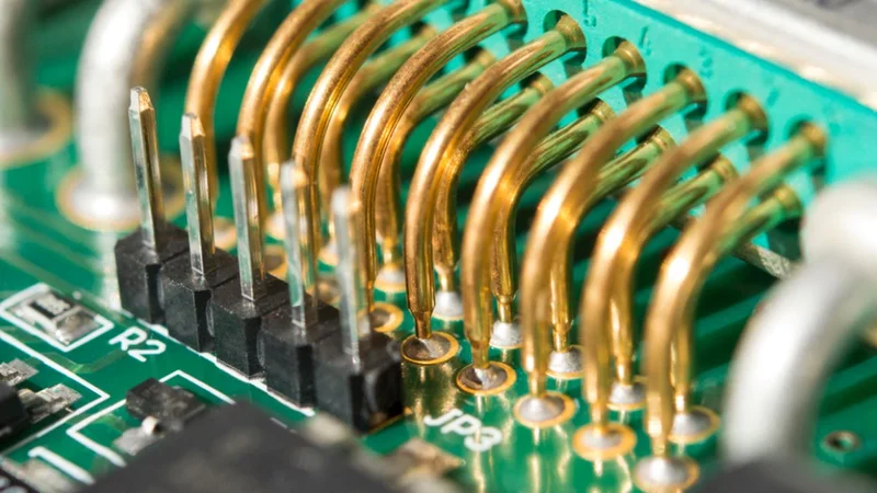
IPC-A-610 Class 3 Electronics Assembly
Key Takeaways
Purpose and Scope: IPC-A-610 is the most widely used acceptance standard for electronic assemblies. It sets visual acceptance criteria for soldered joints, component mounting, hole fill, lead protrusion, cleanliness, and marking.
Three Product Classes: The standard distinguishes Class 1 (general electronic products), Class 2 (dedicated service products), and Class 3 (high-performance/harsh-environment products). A defect in a lower class is also a defect in higher classes.
Condition Categories: Conditions are categorized as Acceptable, Process Indicator, or Defect. Revision J removed the Target category. Acceptable conditions meet minimum requirements. Process indicators do not affect function but suggest process improvement. Defects fail to meet fit, form, or function and require rework.
Key Topics: IPC-A-610 covers solder joint criteria for through-hole and surface-mount devices (including minimum fillet dimensions and hole fill), component orientation, lead protrusion, mechanical assembly, cleanliness, marking, and conformal coating.
Related Standards: It works with J-STD-001 (soldering process requirements), IPC-7711/7721 (rework and repair), IPC-6012 (rigid PCB qualification), and IPC-2221 (generic design rules).
Certification Paths: Certified IPC Specialist (CIS) credentials are for operators and inspectors. Certified IPC Trainer (CIT) credentials qualify individuals to train CIS candidates. Recertification for both must occur every two years.
Introduction
The electronic assemblies must meet strict quality benchmarks to ensure long-term reliability, safety, and performance across industries. The IPC (Association Connecting Electronics Industries) standard, IPC-A-610, serves as the globally recognized guideline for evaluating the acceptability of assembled printed circuit boards (PCBs). From consumer electronics to aerospace systems, IPC-A-610 provides detailed visual and written criteria for solder joints, component placement, cleanliness, and overall workmanship.
Unlike process-focused standards, IPC-A-610 emphasizes inspection and final product quality, enabling engineers, inspectors, and manufacturers to maintain consistent acceptance criteria. The latest revision reflects advancements in miniaturization, high-density interconnects, and modern assembly technologies. By implementing IPC-A-610, organizations can reduce defects, improve product reliability, and align manufacturing outputs with industry expectations. Ultimately, it acts as a critical bridge between design intent and production quality, ensuring that every electronic assembly meets defined performance and reliability standards.
What Is IPC-A-610?
Scope and Purpose
The IPC-A-610 standard, formally titled Acceptability of Electronic Assemblies, is the most widely adopted acceptance standard in the electronics industry for evaluating the quality of a PCB assembly. Rather than defining manufacturing processes, IPC-A-610 provides detailed visual inspection guidelines and acceptance criteria to classify conditions as acceptable, process indicators, or defects across a wide range of electronic products.
It applies to both surface-mount assemblies and through-hole technology (THT), covering critical aspects such as solder joints, component mounting, terminal connections, fillet formation, wetting behaviour, and flux residues. The standard also addresses conformal coating, laminate conditions, and potential component damage, ensuring that printed circuit board assemblies meet defined workmanship standards.
IPC-A-610 is used alongside IPC (Association Connecting Electronics Industries) process specifications such as J-STD-001, which govern how assemblies are built, while IPC-A-610 focuses on visual inspection and final product quality. [1] It defines three classes — Class 1 (general electronic products), Class 2 (dedicated service electronics), and Class 3 (high-performance, high-reliability applications, such as aerospace, automotive, and medical devices) — each with progressively stricter quality requirements.
Revision History
The evolution of IPC-A-610 reflects the rapid advancement of electronics manufacturing, from early through-hole assemblies to modern SMT and high-density PCBAs. The major revisions include A (1983), C (2000), D (2005), E (2010), F (2014), G (2017), H (2020), and the latest IPC-A-610J (2024).
Revision J introduced several important updates to align with contemporary manufacturing practices and companion standards such as IPC J-STD-001. Notably, it eliminated the “Target” condition category, simplifying evaluation into clearer acceptable and defect classifications. The revision also enhanced guidance on conformal coating inspection, improved criteria for cleanliness and flux residues, and clarified acceptance limits for voiding, bubbles, and solder coverage.
These updates ensure that IPC-A-610J remains relevant for modern OEM and EMS environments. This supports consistent process control, reliable inspection outcomes, and compliance with global IPC certification requirements.
The Three Product Classes
IPC-A-610 defines three product classes representing different end-use environments and reliability expectations.
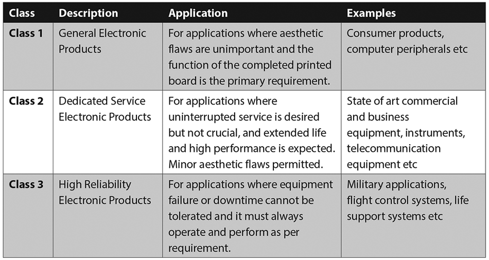
Class 1 – General Electronic Products represents low-cost, high-volume consumer electronics such as toys, simple gadgets, and non-critical electronic devices. The primary focus is functionality rather than aesthetics. The acceptability of electronic assemblies under this class allows minor cosmetic imperfections, provided they do not impact form, fit, or function. [2] Inspection is minimal, and acceptance criteria are lenient, resulting in the lowest manufacturing and inspection cost.
Class 2 – Dedicated Service Electronic Products includes applications like industrial controls, network systems, automotive modules, and home appliances. These general electronic products require a balance between cost and reliability. The IPC-A-610 guidelines for this class demand improved solder joints, proper component mounting, and defined requirements, such as adequate barrel fill-in through-hole technology and well-formed fillets in surface-mount assemblies. Inspection is more rigorous than Class 1, ensuring consistent product quality without high cost.
Class 3 – High-Performance / High-Reliability Products is the most stringent category, covering aerospace, medical devices, and military applications where failure is unacceptable. The IPC-A-610 class requirements enforce the highest workmanship standards, including strict control over solder, terminal connections, wetting, and defect-free PCBs. Here, no cosmetic or functional defects are permitted. These assemblies often require additional standards such as IPC-A-600 and IPC J-STD-001, along with specialized addenda for harsh environments. Consequently, this class involves the highest cost, strictest process control, and most detailed visual inspection.
The selection of the appropriate class is determined by the customer and depends on the product’s operational environment and reliability expectations. If no class is specified, Class 2 is typically used as the default. Importantly, a condition acceptable in a lower class may be classified as a defect in a higher class, reinforcing the progressive tightening of acceptance standard criteria across the three levels.
Recommended Reading: IPC Class System: A Technical Deep Dive into Patent Classification Architecture
Acceptance Condition Categories
The IPC-A-610 standard defines clear condition categories to guide visual inspection and ensure consistent evaluation of PCB assembly quality across the electronics industry. In IPC-A-610J, these conditions are simplified into three categories — Acceptable, Process Indicator, and Defect.
Acceptable condition meets the defined acceptance criteria and ensures reliable performance of the printed circuit board without requiring correction. While the appearance of solder joints or surface-mount components may not be visually perfect, they satisfy the required workmanship standards and pose no risk to product quality. In such cases, inspectors approve the assembly as is and document it for traceability, thereby avoiding unnecessary rework that could cause damage or introduce variability.
Process Indicator represents a minor deviation from the ideal condition that does not affect the form, fit, or function of the electronic devices. The examples include slight discoloration, minor voiding in solder, or small variations in fillet formation. Although these conditions are acceptable, they highlight potential gaps in process control within electronics manufacturing. These indicators are monitored collectively, helping engineers and quality teams identify trends and refine production processes without requiring immediate corrective action.
Defect is a nonconforming condition that violates IPC-A-610 acceptance standard requirements and compromises reliability. Issues such as insufficient through-hole fill, solder bridging, poor wetting, lifted pads, excessive flux residues, or component damage directly impact the performance of high-quality, high-reliability assemblies. Such conditions must be rejected and resolved through repair, controlled rework procedures (often guided by IPC 7711), or scrapping of the affected PCBAs.
If a specific condition is not explicitly covered by IPC-A-610, the default assumption is that it is acceptable unless it adversely affects functionality or long-term reliability. This approach ensures flexibility while maintaining strict compliance with quality requirements in modern SMT and through-hole technology assemblies.
Key Topics Covered by IPC-A-610
Solder Joint Criteria
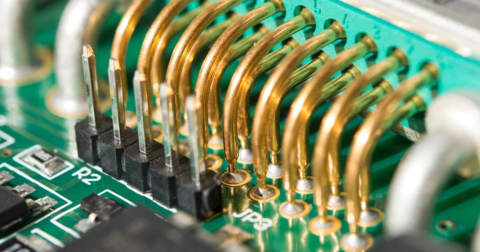
Through-Hole Solder Joints (PTH): IPC-A-610 defines minimum wetting angles, hole fill percentages, and fillet geometry. In class 2 and class 3 assemblies, a minimum barrel fill of 75% is typically required, with defined exceptions (such as ≥50% fill or ≥1.2 mm fillet height) for high-lead-count components. Proper wetting must be evident around the lead circumference, up to 270° on the component side and up to 330° on the solder side for high-reliability applications.
Here, lead protrusion and clinching are equally important! Leads must extend sufficiently to ensure mechanical stability and proper solder flow, while avoiding excessive length that could cause shorts. In high-performance assemblies, precise clinch angles (e.g., 45° for unsupported leads) are required to provide stress relief without inducing component damage.
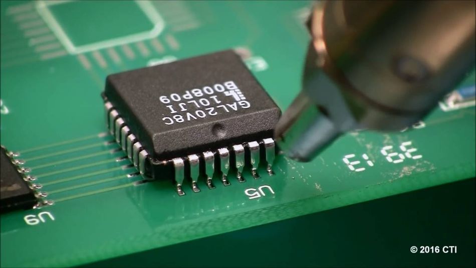
Surface-Mount Solder Joints (SMT): For chip components, the standard defines maximum component overhang, minimum joint width, and minimum fillet height. Acceptable solder joints must exhibit smooth fillets, evidence of proper wetting, and absence of bridging or voids.
For gull-wing and J-lead components, IPC-A-610 specifies additional requirements: maximum overhang (50% for Classes 1 and 2, 25% for Class 3), minimum heel fillet height equal to the lead thickness plus 50% for Class 1, and equal to the lead thickness plus 100% for Classes 2 and 3. Regardless of class, the solder must not contact the component body. Bridging or solder splash is a defect.
Component Orientation and Mounting
Proper orientation of polarized components (diodes, electrolytic capacitors, connectors) is critical to functional integrity. The standard requires that markings or polarity indicators remain visible after assembly. For axial components, leads must be formed to the correct pitch without damaging the body. The body must sit against the board or support as specified. For through-hole components mounted vertically, lead bending must provide stress relief without kinks or nicks.
The mechanical hardware, including connectors, standoffs, and fasteners, must meet drawing specifications, ensuring proper alignment, proper torque, and the absence of burrs or other mechanical defects.
Cleanliness and Residues
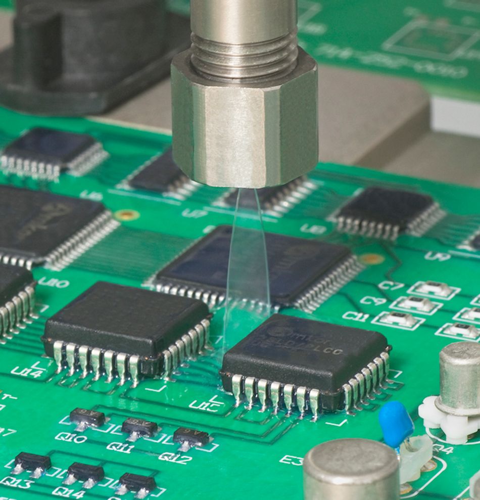
Cleanliness is a key determinant of long-term reliability in electronic devices. Residual contaminants such as flux residues, oils, or particulate debris can lead to corrosion, leakage currents, and reduced insulation resistance. The IPC-A-610 guidelines require assemblies to be free from visible contamination, with stricter requirements applied to class 3 high-reliability applications such as aerospace and medical devices.
The inspection may involve magnification, ultraviolet light, or testing for ionic contamination to verify cleanliness. The standard also cross-references IPC J-STD-001 for detailed cleaning methods and contamination limits, ensuring alignment between process control and inspection criteria.
Marking and Identification
Proper identification ensures traceability throughout the lifecycle of electronic products. Silkscreen markings, reference designators, and revision identifiers must remain legible and durable after PCB assembly and cleaning processes. In coated assemblies, markings must still be readable through the conformal coating, especially for class 3 applications.
The uncontrolled or handwritten markings are generally classified as process indicators unless explicitly approved. Clear identification supports quality audits, maintenance, and compliance with IPC certification requirements.
Conformal Coating and Encapsulation
For assemblies requiring protection against moisture, dust, or chemicals, IPC-A-610 evaluates the appearance of conformal coating rather than prescribing a specific type. The coating should uniformly cover all surfaces, including edges and component leads, without bubbles, voids, dewetting, or bridging between adjacent conductors. J-STD-001 (Section 10.3.5) states that cured coating should be free of bubbles and voids. Once bubbles or voids are present, they must not bridge non-common leads or expose conductors. Otherwise, they are defects. Bubbles that do not violate these criteria are process indicators. [3]
Revision J clarifies acceptance for bubble bridging and includes new graphics addressing voiding in X-ray images. It also emphasizes conformal coating transparency to allow inspection of underlying solder joints. The opaque areas are considered defects unless documented.
Hole Fill, Lead Protrusion, and Clinching
Beyond basic solder requirements, IPC-A-610 defines detailed criteria for hole fill, visible lead ends, and clinching practices. In cases where full barrel fill is difficult, such as thick copper layers or thermal planes, the standard allows classification as a process indicator if minimum thresholds are met.
Proper lead protrusion ensures mechanical retention and reliable solder bonding. Excessive protrusion can lead to electrical shorts, while insufficient protrusion or a lack of a visible lead end is classified as a defect. Controlled clinching improves mechanical stability, especially in through-hole technology assemblies subjected to vibration or thermal cycling.
Bottom-Termination Components, BGA, and BTC
Modern SMT components such as QFNs, LCCs, and other bottom-termination components (BTCs) present unique inspection challenges due to their hidden solder joints. The standard references companion guidelines, such as IPC-7093, for design and assembly best practices. Proper control of solder paste volume is critical; excess paste can cause bridging and component floating, while insufficient paste leads to open circuits.
Ball Grid Array (BGA) components rely on self-alignment during reflow and provide excellent thermal and electrical performance. However, inspection of BGA solder joints requires X-ray analysis due to their hidden nature. Additionally, moisture sensitivity in advanced semiconductor packages requires strict storage and handling procedures to prevent defects such as delamination or voiding.
Recommended Reading: IPC Class 2 vs Class 3: Understanding the Critical Differences in Electronics Manufacturing Standards
Relationship to Other IPC Standards
The IPC-A-610 standard is part of a broader ecosystem of IPC documents that collectively define quality requirements, process control, and acceptance criteria throughout the entire PCB assembly lifecycle.
J-STD-001: Requirements for Soldered Electrical and Electronic Assemblies
J-STD-001 is the process standard for producing reliable soldered connections. It defines materials, methods, and acceptance criteria for soldering wires, terminals, through-hole, and surface-mount assemblies. The standard covers requirements such as solderability, flux selection, thermal profiles, cleaning, and process control. Class definitions in J-STD-001 (A, B, C) align with those in IPC-A-610. The customer determines which class applies. The process standard is used during manufacturing, while IPC-A-610 is used for end-product inspection.
IPC-7711/7721: Rework, Modification, and Repair
The combined IPC-7711/7721 document provides step-by-step procedures for rework, repair, and modification of electronic assemblies. IPC-7711 covers rework (bringing a non-compliant product back to its original requirements). IPC-7721 covers repair and modification (restoring function or altering configuration). It offers procedures for replacing components, repairing lifted pads, patching damaged traces, and re-balling BGAs. The standard defines classes (1, 2, 3) similar to those in IPC-A-610 and emphasizes that allowable procedures depend on the product class. Using IPC-7711/7721 ensures repairs maintain the same quality level as original assemblies.
IPC-6012: Qualification and Performance for Rigid Printed Boards
IPC-6012 defines qualification and performance requirements for rigid PCBs. It works with IPC-6011 (performance classes) and IPC-A-600 (acceptability) to ensure that bare boards meet specified thickness, hole plating, and dielectric properties. Revision F (2023) lists vertical hole fill requirements: minimum vertical fill of 50% for Class 2 and 75% for Class 3. [4] The standard also references addenda such as IPC-6012FS for space/military, IPC-6012EM for medical, and IPC-6012FA for automotive.
IPC-2221: Generic Standard on Printed Board Design
IPC-2221 provides design guidance for conductor spacing, current capacity, thermal management, and mechanical considerations on PCBs. It defines design classes (1, 2, 3) and establishes rules for trace widths, spacing, via design, and material selection. Designers use IPC-2221, along with IPC-A-610, to ensure that boards meet acceptability criteria after assembly.
IPC-7093: Design and Assembly Process Implementation for BTCs
IPC-7093 offers guidance for bottom-termination components. It covers stencil design, solder paste deposition, component placement, reflow profile, cleaning, and inspection for BTCs. Controlling solder paste volume is critical: too much paste causes bridging and floating, while insufficient paste leads to opens. The document also highlights challenges with cleaning and X-ray inspection due to small standoff heights.
Recommended Reading: IPC Standards: The Definitive Guide for Electronics Engineers and PCB Designers
Certification and Training
IPC offers several certification programs to ensure that personnel understand and correctly apply the standard.
CIS (Certified IPC Specialist): Intended for operators, assemblers, and quality inspectors. CIS training covers the acceptability criteria of IPC-A-610 and emphasizes the ability to recognize Acceptable, Process Indicator, and Defect conditions. The certification is valid for two years.
CIT (Certified IPC Trainer): Aimed at individuals who train CIS candidates within an organization. The four-day CIT class covers each section of IPC-A-610, culminating in an exam with a passing score of at least 80%. CITs are authorized to train and certify CIS personnel and must maintain their certification by teaching at least two courses during the certification period [10].
CSE (Certified Standards Expert): Focuses on advanced understanding of IPC standards to provide in-house expertise. CSEs help interpret and apply standards correctly. They are not necessarily trainers.
Recertification for all credentials is required every two years, with a defined grace period. The renewal can be achieved through challenge examinations or refresher courses, ensuring alignment with the latest revisions, such as IPC-A-610J. Continuous training is essential as electronic devices evolve, helping maintain high-quality, high-reliability standards in modern SMT and mixed-technology manufacturing environments.
Practical Use in Manufacturing
Implementing IPC-A-610 in production requires integrating its criteria into inspection workflows, process control, and design feedback loops.

Inspection Workflow
Assemblers typically conduct inspections at three stages: first-article inspection, in-process sampling, and final inspection. The first article inspection verifies that the first boards off the line meet all specified criteria. In-process sampling monitors consistency. Final inspection confirms that assemblies conform before shipment. Inspectors use magnification (5x-10x for small components) and measurement tools to assess features such as lead-to-pad alignment, fillet dimensions, and solder coverage. When joints are hidden under BGAs or BTCs, X-ray or other non-destructive evaluation methods are used.
Dispositioning Defects and Rework
When inspectors identify defects, they must determine whether rework, repair, or scrap is appropriate. Rework is performed in accordance with IPC-7711 procedures to bring the product back into compliance. Repairs follow IPC-7721 guidelines when original requirements cannot be fully restored. Process indicators prompt the manufacturing engineer to review process parameters (for example, solder paste deposition or reflow profile). Statistical process control (SPC) is often used to monitor process indicators and defects across lots, enabling data-driven process improvement.
Design-for-Manufacturing Feedback
IPC-A-610 criteria should feed back into design. If assemblies consistently exhibit marginal hole fill due to large thermal planes, designers can adjust via diameters or thermal relief patterns. If lead protrusion cannot be achieved because the leads are too short, component selection or board thickness may need to be revised. DFM reviews using IPC-2221 and 7093 guidelines reduce the likelihood of process indicators and rework.
Automation and Future Trends
Automated optical inspection (AOI) and automated X-ray inspection (AXI) systems implement IPC-A-610 rules algorithmically. As artificial intelligence is integrated into AOI, machines will better distinguish acceptable fillet variation from defects and identify process indicators. The clarified voiding and bubble acceptance criteria by Revision J facilitate machine learning by providing clearer visual boundaries. The industry is also discussing a Class 3A category to address ultra-high-reliability applications like implantable medical devices and autonomous vehicles. This class would have even stricter limits on defects and require objective evidence for process control.
Recommended Reading: What is Electronics Manufacturing Services (EMS): A Comprehensive Guide for Engineers
Conclusion
IPC-A-610 plays a central role in ensuring that assembled PCBs meet their intended function and reliability goals. Defining acceptance criteria for solder joints, component placement, cleanliness, and marking enables consistent communication between design, manufacturing, and quality teams. The classification system (Classes 1-3) tailors requirements to application criticality, while condition categories (Acceptable, Process Indicator, Defect) guide disposition decisions. Once used alongside process standards like J-STD-001 and repair standards such as IPC-7711/7721, IPC-A-610 forms part of an integrated quality management system that spans design, manufacturing, and rework. By understanding and applying IPC-A-610, engineers and inspectors ensure that electronic products deliver reliable performance in consumer, industrial, and high-reliability environments.
Frequently Asked Questions (FAQs)
1. What is IPC-A-610?
A. IPC-A-610, titled Acceptability of Electronic Assemblies, is the industry standard that provides visual acceptance criteria for assembled PCBs. It defines what constitutes acceptable, process indicator, and defect conditions for solder joints, component placement, lead protrusion, hole fill, cleanliness, and marking.
2. What are the three IPC-A-610 classes?
A. The standard defines Class 1 (general electronic products), Class 2 (dedicated service products), and Class 3 (high-performance/harsh-environment products). Class 3 requires the highest workmanship and reliability. Class 1 is the most lenient. A defect in a lower class is automatically a defect in higher classes.
3. How does IPC-A-610 relate to J-STD-001?
A. J-STD-001 specifies materials, methods, and process control for soldering. IPC-A-610 evaluates the finished assembly. They are used together: J-STD-001 ensures reliable soldering processes, and IPC-A-610 confirms that the finished product meets visual acceptability criteria.
4. What changed in IPC-A-610 Revision J?
A. Released in 2024, Revision J removed the Target condition category, clarified definitions, and added new images addressing voiding and bubbles in conformal coatings. It also improved guidelines for conformal coating inspection and cleanliness standards.
5. What is a Certified IPC Specialist (CIS) and a Certified IPC Trainer (CIT)?
A. A CIS is trained to recognize acceptable, process indicators, and defect conditions on assemblies. The credential is for operators and inspectors. A CIT is an instructor qualified to teach IPC-A-610 to CIS candidates. CIT training is more extensive and authorizes the trainer to issue CIS certificates. Both certifications must be renewed every two years.
6. Is IPC-A-610 mandatory?
A. IPC standards are voluntary unless called out by contract or regulatory requirements. Many OEMs and EMS providers adopt IPC-A-610 to ensure consistent quality and to support audits. Customers specify the class and any addenda applicable to their product.
7. How often is IPC-A-610 updated?
A. IPC typically revises A-610 every 3-5 years. The revision history shows updates in 2014 (F), 2017 (G), 2020 (H), and 2024 (J). Staying current with revisions ensures that organizations apply the latest criteria and guidance.
References
[1] IPC. IPC-A-610J Acceptability of Electronic Assemblies, 2024 Revision and Revision History [Cited 2026 April 20]; Available at: Link
[2] ANSI. Acceptability of Electronic Assemblies (IPC A-610J-2024) [Cited 2026 April 20]; Available at: Link
[3] EPTAC. Bubbles in Conformal Coating and Vertical Fill Guidance [Cited 2026 April 20]; Available at: Link
[4] Wevolver. IPC Class 2 vs Class 3: Understanding the Critical Differences in Electronics Manufacturing Standards [Cited 2026 April 20]; Available at: Link
in this article
1. Key Takeaways2. Introduction3. What Is IPC-A-610?4. The Three Product Classes5. Acceptance Condition Categories6. Key Topics Covered by IPC-A-6107. Relationship to Other IPC Standards8. Certification and Training9. Practical Use in Manufacturing10. Conclusion11. Frequently Asked Questions (FAQs)12. References