Design for Manufacturing (DFM): The Ultimate Guide to Streamlining Product Development and Reducing Costs
Design for Manufacturing approach focuses on making product creation as simple and efficient as possible. Implementing DFM concepts reduces material waste, costs, and improves assembly times. Get the most out by following these guidelines from industry experts on Design for Manufacturing (DFM).

Last updated on 25 Apr, 2024. 14 minutes read
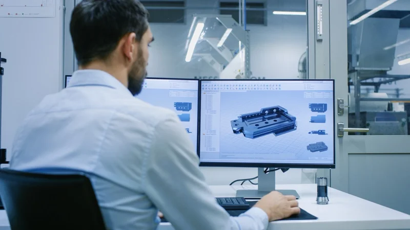
Understanding the Fundamentals of DFM
Developing a design for manufacturing strategy is the first thing product owners should focus on when creating a new product. The earlier you focus on DFM techniques, the more time and money you can save in the long run [1][2].
No matter the product, a strategic DFM approach will always include all stakeholders. This ensures thorough consideration and planning of every aspect of the project.
The primary difference between DFM and other conventional design methods is that DFM starts thinking about manufacturability at the conceptualization stage.
Key principles and concepts behind DFM:
- Process: Optimizing the manufacturing process for each component while taking tolerances and necessary materials into account.
- Design: Keeping things simple is typically the way to go; this applies to production, consumption, upkeep and expense.
- Materials: Material selection impacts price and quality.
- Environment: At every stage of product creation, you must consider the intended application of your product.
- Testing: In every step, the product or component must meet or exceed all applicable industry requirements.
In the medical device industry, DFM is all about making surfaces that are smooth and simple to clean. This ensures the devices are in accordance with regulations and that patients are safe. In automotive engineering, the goal of DFM is to save maintenance time and expenses by making engine parts that are easy to access and replace. Aerospace DFM solutions aim to improve fuel economy and performance by creating lighter and less complex aircraft components.
DFM methodology is useful in electronics production because it helps optimize component designs for reliability while also improving ease of assembly and production costs. Even bicycle production is not exempt from DFM principles. They govern the design of frames to provide simple assembly with varied forks, wheels and components; this broadens component compatibility and flexibility across diverse bike configurations.
Recommended reading: Accelerated Electronics Product Design Using Cloud Manufacturing
The DFM Mindset: Designing with Manufacturing in Mind
Maximizing supply chain efficiency begins with developing a DFM mindset. For this, you need to know how to implement limitations on a product's design and production. For example, by keeping injection molding restrictions in mind early on, such as avoiding complicated component geometries and limiting undercuts, a DFM approach helps keep design revisions affordable and on track. In a similar vein, optimizing sheet metal designs with suitable bend radii and nesting considerations can help head off production issues, cutting down on iterations and reworking later on.
Adopting a DFM mindset ensures the materials and components are compatible and easily accessible throughout production. It also helps businesses speed up the product development process, which, in turn, speeds up the product launch. A speedy product launch benefits a business in several ways:
- Competitive advantage
- Greater adaptability
- Greater ability to meet customer demands
- Better brand credibility and loyalty
- Waste reduction across the supply chain
Collaborating across disciplines is a great approach to fostering a DFM mindset. When engineers and designers work together, it becomes easier for them to spot problems early on in the manufacturing process. They can share notifications with one another about product design changes that make the product more cost-effective. Staying in contact with one another throughout the entire design phase is essential to facilitating effective DFM approaches.
Organizations can also promote DFM principles by cultivating a feedback loop culture and a culture of continuous development. Regular design reviews should include soliciting feedback from manufacturing teams and learning from previous design stages.
Designers can optimize designs proactively by evaluating moldability, assembly feasibility and material selection when using state-of-the-art design and simulation tools. This form of optimization can be incredibly advanced when using computer-aided design (CAD) software that integrates DFM analysis capabilities.
The last step in cultivating a DFM mindset is to encourage engineering and design teams to train and educate themselves on DFM concepts. This means employers must provide resources, courses and case studies that highlight good DFM processes.
Hands-on learning experiences in any of the following areas can help you develop a DFM mindset:
- Collaborative projects
- Practical design reviews
- Interactive workshops
- Visits to manufacturing plants
- Design challenges
- Continuous improvement projects
- Failure analysis exercises
- Prototyping
- Cost estimation activities
Collaborating Across Disciplines for Optimal Results

For a product's development to be a success, the design and production teams must work together. The Tesla Model S is an exemplary example of what can happen through multidisciplinary collaboration. With the engineering and design teams working together alongside other production specialists, they were able to maximize the efficiency of the assembly processes. The enhanced efficiency touched every part of the manufacturing process thanks to the use of state-of-the-art technologies like aluminum casting and robotic assembly.
Recommended reading: Pick and Place Robots: An In-Depth Guide to Their Functionality and Applications
Advancements in DFM Techniques and Technologies
There have been many advancements in DFM strategies. For example, engineering software from Siemens NX and CATIA from Dassault Systèmes enables the simulation of machining, casting and shaping, among other industrial processes. Engineers then use the preliminary modeling to detect possible problems.
The incorporation of Design for Assembly (DFA) concepts into DFM is another significant development. By standardizing components, reducing the number of parts and providing for simple handling and alignment during assembly, DFA aims to simplify product assembly. Companies like Toyota use DFA methods to simplify assembly processes and cut labor costs while also producing higher-quality products.
Leveraging Simulation and Analysis Tools for DFM
Simulation and virtual reality technology being used in healthcare to enhance patient experiences and improve product training.
Giving the client and internal teams a bird's-eye perspective of the facility floor layout, resource needs and process flow is now possible using virtual reality technology. With one click, you can launch a virtual version of the product to see if you need to make any changes. Most importantly, you can use simulation to guide your production process.
The use of simulation and analysis tools continues to reshape the industrial industry. No other technology has the ability to shorten the time it takes to get from design to production and lower the manufacturing costs associated with bringing a product to market.
You can use analysis and simulation tools to examine multiple parts of the manufacturing and design processes, including:
- Layout
- System constraints
- Production changes
- System performance
- Labor
- Rules and policies
Simulation benefits customers, equipment suppliers, and supply chain partners. It also lessens the hassle and cost of the old-fashioned trial and error method, which can lead to unnecessary rearranging of machinery on a production line throughout the manufacturing operations.
Some of the top reasons to incorporate simulation into your DFM mindset are:
- Streamline system performance with decision-support and training
- Handle complicated interdependent variables and dynamics
- Pay close attention to detail and enhance system comprehension
- Enable advanced "what if" assessments
Due to its ability to reveal your processes and compel you to pay close attention to detail, simulation has become practically indispensable in modern times. It captures subtleties, and in doing so, you gain a better understanding of your organization. In contrast to a data spreadsheet, you can see the interplay of how one activity affects another.
To further aid in problem identification and parameter optimization for effective production, process simulation tools mimic machining, casting and forming operations. In the end, these tools help engineers optimize designs, anticipate performance and evaluate manufacturability. This allows for quicker time-to-market, lower costs and better product quality.
There are numerous simulation and analysis tools to choose from. Finite Element Analysis (FEA) is a powerful method for optimizing materials and reducing weight; this method assesses how designs will react under various loads and circumstances.
Computational Fluid Dynamics (CFD) evaluates fluid flow and heat transport with the goal of developing better cooling systems and fluid-based manufacturing processes. With Moldflow Analysis, you can optimize your component design and mold setup for injection molding. It simulates the filling, packing and cooling stages, which helps to reduce cycle times and errors.
Here are some more simulation and analysis tools:
| Tool | Features | Benefits |
| Process simulation | Simulates a number of production steps, including turning, casting, and shaping. | Identifies potential problems, adjusts process parameters (such as feed rates and cutting speeds), and increases process efficiency. |
| Discrete event simulation | Models complex processes and systems using discrete occurrences (such as logistics in a supply chain or activities during manufacturing operations). | It boosts efficiency by maximizing the use of available resources and eliminating inefficiencies. |
| Design of experiments | Methodically plan trials to examine and enhance various factors. | Determines what matters most for production processes, finds the sweet spot for process parameters, and cuts down on costly and time-consuming experiments. |
| Failure mode and effect analysis | Systematically assesses probable failure mechanisms for components or processes. | Determines the most pressing threats, ranks them in order of severity, and then takes preventative action to minimize downtime, increase safety, and improve dependability. |
| Digital twin simulation | Makes a digital copy, or "twin," of an actual item or process. | Allows for predictive maintenance, performance optimization, scenario testing, and real-time monitoring without impacting actual operations. |
Statistical process control | Uses statistical approaches to oversee and manage production operations. | It helps identify outliers, keeps operations stable, boosts product quality and cuts down on waste by keeping processes within specified parameters. |
Additive Manufacturing: A Game-Changer for DFM
3D printing and Additive Manufacturing (AM) continue to change the manufacturing game in many ways [3]. They help make designs more versatile, cut down on material waste, save time and money and much more. AM enables previously inconceivable, elaborate and complicated geometries by building items layer by layer.
The capacity to generate intricate textures, patterns and geometries is only one of the many design freedoms made possible by additive manufacturing. AM can merge dozens of separate components into one or condense assembly into one, like two sides of a hollow item. This has the potential to reduce the number of steps, materials, suppliers, glue, fasteners and total parts required to make a certain item.
Thanks to AM, aeronautical designs can now undergo rapid prototyping while reducing weight. By using 3D-printed heat exchangers, Aerojet Rocketdyne was able to save 75% on production time and costs while simultaneously increasing the heat exchangers' endurance and strength [4]
Medicine is another area where 3D printing has had a significant impact. Patients with burn injuries can now have artificial skin printed using 3D technology for transplantation. 3D printing also has the potential to expedite the development of pharmaceuticals and enable on-demand production. To better prepare for surgery, 3D printed models mimic the anatomy, size, texture and color of real organs, tissues and lesions.
Recommended reading: Design for Metrology in Additive Manufacturing
Recommended reading: Functional Aesthetics in Additive Manufacturing
Advanced Materials and Processes in DFM
Material selection has a significant impact on DFM results because different materials have distinct qualities that can be important during design and production . For example, Carbon Fiber-Reinforced Polymers (CFRP) and other lightweight, high-strength composite materials have many potential aircraft uses. Engineers can use them to improve structural integrity, reduce weight and increase fuel economy.
Methods for cutting costs via material selection [5] include a wide range of techniques with the overarching goal of enhancing product performance and quality while reducing costs. Listed below are some methods for cutting costs by choosing the right materials:
- Life cycle cost analysis
- Value engineering
- Material substitution
- Bulk purchasing and negotiation
- Standardization
- Waste reduction and recycling
- Local sourcing
- Design optimization
- Technology and innovation
- Regulatory and environmental considerations
Cost, performance, lead time and scalability are some of the technical issues and trade-offs that come into play when choosing materials and processes for DFM. Opting for a more straightforward manufacturing technique, such as injection molding, rather than CNC machining can lead to reduced production costs but less design flexibility. However, choosing a more specialized material with better qualities can raise material prices and lead times.
To maximize DFM results and strike the right balance between design needs and production limitations, engineers must take these tradeoffs into account. The key to a successful DFM methodology deployment is using a comprehensive strategy that combines material science, industrial knowledge and design optimization throughout the entire design phase.
Applying DFM in Real-World Engineering Projects
Reviewing case studies can help you gain a better understanding of the benefits of DFM. These case studies are a great way to compare your results to those of your competitors, learn from industry leaders' mistakes and get ideas for your own projects.
Case Study 1: Automotive Industry
The goal of this case study [6] was to make diesel engines more economically viable by reducing manufacturing and assembly costs. The design study revealed a production time of about 5 hours and 35 minutes, and a production capacity that corresponds to one engine every seven minutes. The use of DFM techniques led to the discovery of opportunities to alter the production process in order to lower overall costs. Throughout the assembly process, it became clear to the component supplier that these milling and non-pass bores were unnecessary for the assembly to continue.
The elimination of the block painting was another outcome of the investigation. Assembling the engine revealed that the chassis and engine were painted black, covering up any prior painting. This resulted in a very redundant painting job on the cylinder block. Adjustments allowed for a 0.26% savings in the cylinder block and a 0.13% drop in the cost of the structural and sealing subsystems. Another change was to remove the portrait and spot-facing seats of the speed sensor. As a result of this modification, the cylinder's price dropped by 0.18%.
Case Study 2: Consumer Electronics
This case study shows how important design in manufacturing is for improving electronics manufacturing efficiency and component design. In this scenario, the customer had trouble getting the flatness just right and encountered ejection problems when molding.
Doing a DFM analysis before beginning the mold design process helped identify key areas that needed improvement. Engineers optimized the gear teeth' arrangement using DFM principles and purposefully reduced rib features to streamline the component design. This simplified manufacturing for the consumer while also reducing material use, cost and overall component weight.
Adjustments guided by DFM also made ejection better by making sure the molded product came out of the mold more uniformly. Adding ejection surfaces to the rib connection points significantly improved the part's reliability and manufacturability.
Recommended reading: RF PCB: Design, Materials, and Manufacturing Processes
Challenges and Considerations in Implementing DFM
A lack of cross-disciplinary teamwork [7], limits imposed by present manufacturing capacity and a desire to stick with traditional design approaches are common problems that engineers have when trying to employ DFM methodology in their projects. Other possible obstacles include minimizing costs, making the most efficient use of materials and balancing design goals with manufacturing constraints.
Design trade-offs and production limitations are common sources of technical difficulties. To overcome these obstacles, you must:
- Maintain a happy medium between the material's machinability and formability as well as its strength, cost, and availability throughout production.
- Keep track of the complexity of your parts to make assembly easier and boost production efficiency.
- Ensure that items fulfill functional requirements by aligning design tolerances with production capabilities.
- Avoid expensive redesigns by designing components with production equipment and tooling restrictions in mind.
- Prioritize early-stage design analysis to proactively address manufacturability concerns and maximize project results.
- Promote cross-functional cooperation.
- Use sophisticated simulation technologies.
- Cultivate a culture that appreciates DFM principles.
Key considerations for successful DFM implementation:
- Using DFM concepts early in the design process
- Multidisciplinary teams working together on the same goal (e.g., design, engineering, production)
- Assessing manufacturability via the use of state-of-the-art simulation and analytical tools
- Improving via cost-effectiveness and performance optimization
- Minimizing complexity and manufacturing problems via simplification of part geometries
- Keeping production limits and capacities in check while meeting design specifications
- Refining the design iteratively using prototypes and testing feedback
- Prioritization of learning from previous initiatives and achieving continual improvement
Balancing Design Innovation and Manufacturing Constraints
The trade-off between design complexity and manufacturability is a real concern in the realm of innovative products. When designing for simplicity rather than complexity, it is important to avoid sacrificing aesthetics or utility in favor of convenience of manufacture.
Cutting-edge materials can boost product performance, but they can also be hard to come by or expensive. Finding the sweet spot requires looking at several materials that are affordable, have acceptable performance and are readily available.
When it comes to design priorities, there may be tension between those that prioritize utility and those that prioritize efficient manufacturing. This is why, when designing with both user demands and manufacturability in mind, it becomes necessary to modify the design iteratively.
Here are some ways to find a happy medium between innovation and manufacturing:
- Collaborate early: Have manufacturing specialists weigh in on design considerations from the very beginning to help spot problems, particularly those relating to production limits.
- Using iterative prototyping: You can test and improve designs with the help of input from manufacturing trials. As a result, you can optimize them for production.
Ensuring Effective Communication and Knowledge Transfer
When using DFM principles, documentation and standardization are of the utmost importance in promoting knowledge transfer and ensuring good communication between the design and production teams. Documentation that is easy to read and comprehend lays the groundwork for cooperation and understanding by recording design intent, production needs, and important specifications.
Enhanced documentation also allows for the sharing of information across different teams and stages of a project, which in turn decreases the likelihood of misunderstandings and guarantees uniformity in the design and manufacturing procedures. By standardizing procedures, terms and design principles, you can reduce ambiguity and maximize clarity, which in turn facilitates effective teamwork and problem resolution.
Tips for improving the way you and your team work together include:
- Forming interdisciplinary teams with specialists from design, engineering, production and quality assurance.
- Meeting often, providing updates and using collaborative technologies to ensure that the design and production teams are communicating openly and regularly.
DFM and Industry 4.0
Many promising new avenues for improving manufacturing processes and products are opening up as a result of combining DFM with cutting-edge technologies. Industrial equipment, for example, can transmit data in real-time through the use of Internet of Things (IoT) devices, which can reveal information about production efficiency and any problems with manufacturability. To automate decision-making, optimize process parameters and forecast industrial outcomes, artificial intelligence (AI) and machine learning (ML) algorithms can examine huge amounts of information provided by IoT sensors.
Ultimately, DFM and the integration of Industry 4.0 technologies allow for:
- Automated decision-making
- Real-time monitoring
- Predictive analytics in industrial processes
DFM 4.0 offers many advantages, including:
- Better product quality
- More efficient manufacturing
- Less downtime due to predictive maintenance
- Quicker reaction to fluctuating market needs
Conclusion
DFM improves production results and encourages teamwork between the design and manufacturing departments by facilitating the exchange of information and ideas. Working together like this shortens the time it takes to build a product, cuts down on mistakes and simplifies the design process.
The IoT, AI and ML are just a few of the new technologies that will propel DFM into the future and bring about Industry 4.0 practices. The quality of products and their ability to meet customer requests will be even better thanks to these innovations, which will allow for automated decision-making, real-time monitoring and predictive analytics.
By further integrating DFM with Industry 4.0 technology, we'll continue to see transformations in manufacturing processes. Most importantly, we'll be able to achieve more sustainable, efficient and agile engineering methods in the future.
Recommended reading: Design Guidelines for Manufacturing and Assembly
Frequently Asked Questions
1. Will a softer material always work better?
Yes, softer materials usually work better. Working with softer materials allows for greater control over cutting speed and depth, which in turn reduces processing time. In addition to increasing tool wear, harder materials can cause machine wear from the harder chips they produce.
2. How does DFM affect product quality?
DFM effects can improve product quality in several ways:
Simplified design
Optimized material selection
Improved assembly processes
Reduction of manufacturing variabilities
Enhanced testing and validation
3. What are the best tools to use for DFM?
The successful implementation of DFM techniques relies on a number of tools and software programs, such as:
Computer-aided design software
Design analysis software
Finite element analysis software
DFM software modules
Simulation tools
Collaboration platforms
4. Will I save money with DFM practices?
Throughout a product's lifetime, using DFM principles can result in substantial cost reductions in the following areas:
Reduced material waste
Lower production costs
Fewer reworks and iterations
Improved quality and reliability
Optimized tooling and equipment
5. What is the most important part of DFM?
One of the most important parts of DFM is incorporating it early on in the product development phase. Using DFM early on in the development cycle helps to match design choices with production capabilities and restrictions, which in turn reduces the possibility of expensive adjustments later on.
References
[1] Siemens. Early DFM is more important than ever. Link
[2] Pacific-Research. Why DFM is important. Link
[3] Fictiv. 3D printing in aerospace. Link
[4] Additivemanufacturing. Aerojet Rocketdyne saved 75% on production time using 3D printed heat exchangers. Link
[5] Ncbi. Cost cutting methods via material selection. Link
[6] Slideshare. DFMA with Case Study -Diesel Engine Cost Reduction. Link
[7] Researchgate. Cross-disciplinary in collaborative design case study. Link