How to Use a Multimeter: Engineering-Grade Techniques for Accurate Measurements
Learn how to use a multimeter with engineering-grade precision. This technical guide explores advanced measurement techniques, safety CAT ratings, and error minimization strategies for high-fidelity diagnostics.

31 Mar, 2026. 13 minutes read
Key Takeaways
Select the Right Measurement Mode: A multimeter is an essential tool with modes for measuring voltage, current (amps and milliamps), ohms, continuity, capacitance, diode forward voltage, and more. Knowing when to choose auto-ranging versus manual ranging improves efficiency and protects the meter.
High Input Impedance Minimises Circuit Loading: High-impedance DMMs (1 MΩ to 10 MΩ) barely affect the part of the circuit being measured. Low-impedance settings remove ghost voltages but draw more current, so use them only when verifying the presence or absence of voltage.
Understand Voltage, Current and Resistance Measurement Methods: Voltage is measured across points, current through a branch, and resistance via a known test current (R = V/I). Always connect the red probe to the positive terminal and the black probe to the negative terminal.
For Low Resistance, Use Four-Wire Kelvin Measurement: A 4-wire setup separates the force leads from the sense leads, eliminating lead resistance and enabling milliohm accuracy. Conventional 2-wire measurements include test-lead resistance.
True RMS meters are Vital for Non-Sinusoidal Waveforms: True RMS instruments calculate the heating-equivalent value of a waveform, whereas average-responding meters multiply a rectified average by a fixed factor. Non-linear loads found in modern power supplies, LED drivers, and EV chargers distort waveforms and require true-RMS measurement.
Follow Safety Standards and CAT Ratings: Measurement categories defined in IEC 61010-1 dictate the transient withstand capability of a meter. Use CAT I instruments only on circuits not connected to mains, CAT II for plug-in loads, CAT III for fixed installations and CAT IV at service entrances.
Introduction
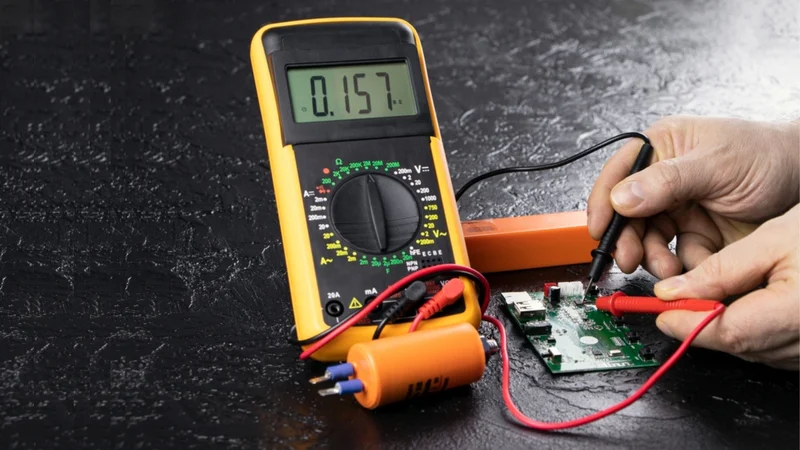
Digital multimeters (DMMs) are common in electronics design, automotive diagnostics, industrial maintenance and electrical engineering. From verifying the tolerance range of a power supply in a microcontroller to diagnosing why an industrial motor starter refuses to energise, a multimeter enables engineers to quantify voltage, current and resistance in real time. Understanding how to use a multimeter is, therefore, a critical skill for engineers working across electronics, power systems, and embedded applications.
The apparent simplicity of this instrument belies a wealth of theory: the meter itself is part of the circuit under test, and its internal resistance, measurement method and category rating determine how accurate and safe the measurement will be.
Curious about, how to use a multimeter? Tutorials focus on basic DIY usage, leaving gaps for advanced concepts such as true-RMS measurement, CAT safety ratings, Kelvin four-wire resistance and the effects of input impedance and burden voltage. This guide on how to use a multimeter focuses on techniques that minimize error and improve measurement confidence. From selecting the appropriate measurement mode to interpreting readings under real-world conditions, each step plays a vital role in ensuring accuracy.
Fundamentals of Multimeters
Multimeter is a versatile electronic measuring instrument used to quantify multiple electrical parameters within a single device. It integrates the functionality of voltmeters, ammeters, and ohmmeters, enabling engineers to measure voltage, current, resistance, and additional parameters such as capacitance, frequency, and diode characteristics.
In engineering practice, multimeters are essential for circuit validation, fault diagnosis, and performance analysis. Their effectiveness depends not only on measurement capability but also on input impedance, accuracy class, resolution, and safety rating.
Basic Functions and Controls
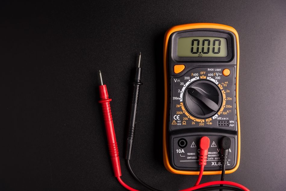
A multimeter combines several measurement functions into one portable tester. The most common controls include:
Selector Switch: Chooses measurement mode (voltage, current, resistance, capacitance, diode test, continuity, frequency). The digital multimeters often have auto-ranging capabilities that select the appropriate measurement range automatically. Manual ranging multimeters let users set ranges, which is helpful when dealing with high current or unknown voltages.
Red and Black Probes: The red probe connects to the positive side, or input jack labelled VΩmA, A, or +. The black probe connects to the common (COM) or negative terminal. Test leads should be rated for the voltage and current being measured.
Display and Units: Digital displays typically show 3.5 to 6.5 digits. Analog meters use a moving coil and a scale; they require manual zeroing and are more susceptible to parallax errors but provide useful trend indication.
Input Jacks: Separate jacks are provided for high-current measurements (often labelled 10 A or A), low-current/milliamps (mA/uA), and general voltage/resistance (VΩ). Always select the correct jack and range to avoid blowing the internal fuse.
Auto-Ranging vs Manual Ranging
The auto-ranging digital multimeters simplify operation by selecting an appropriate scale automatically. However, manual ranging remains valuable in engineering practice:
Auto-Ranging is ideal when the approximate magnitude of the measured quantity is unknown. It prevents overload conditions and speeds up troubleshooting.
Manual Ranging allows engineers to lock the range, providing a stable reading when monitoring slowly varying signals or when measurement noise might cause the auto-range to jump.
Digital vs Analog Meters
Digital multimeters dominate modern laboratories because of their high input impedance and measurement accuracy.
High-Impedance DMMs exhibit input resistances of 1 MΩ to 10 MΩ, meaning they draw minimal current from the circuit and therefore do not significantly alter circuit performance.
Analog Meters and solenoid testers fall under low-impedance (Low Z) devices with input impedance ranging 2 kΩ to 100 kΩ. Low-Z testers intentionally load the circuit to eliminate ghost voltages, but can trip ground fault circuit interrupters or alter sensitive electronic circuits.
Dual-Impedance Meters offer both High Z and Low Z options for different applications.
Safety and Compliance
Multimeters must comply with the IEC 61010-1 standard, which defines measurement categories (CAT) based on transient overvoltage withstand capability. Selecting the proper CAT rating protects both the meter and the user:
CAT I instruments are intended for measurements on circuits not directly connected to mains, for example, battery-powered electronics or low-energy circuits on prototyping boards.
CAT II covers branch circuits that power plug-in loads, such as household appliances and portable tools.
CAT III meters can be used on permanently installed equipment such as motor control centres, lighting circuits, and industrial wiring.
CAT IV is reserved for measurements at the service entrance or on power lines upstream of the main overcurrent device.
Example: The meter rated CAT III 600 V can be used for CAT II measurements at higher voltages, but a CAT II meter must never be used where CAT III or CAT IV conditions exist. [1] It is better to choose fuses and test leads rated for the same category and voltage as the meter.
Recommended Reading: Understanding Multimeter Symbols: A Comprehensive Guide for Engineers
Measuring Voltage
DC Voltage Measurement
Voltage (the potential difference between two points) is measured by placing the multimeter probes across the circuit element. For accurate DC Voltage measurement:
Set the Meter to VDC. On a dual-impedance meter, ensure the high-impedance mode is used unless ghost voltages are suspected.
Connect the black probe to the ground or negative terminal of the circuit and the red probe to the point where voltage is to be measured.
Observe Polarity. Most digital meters display a negative sign if the probes are reversed.
Because a high-impedance meter draws negligible current, the reading reflects the true voltage of the circuit.
In sensitive circuits (such as microcontroller power rails), even a 1 MΩ input could load the source if the source impedance is comparable; premium benchtop DMMs offer 10 MΩ or even 1 GΩ inputs.
AC Voltage Measurement and True RMS
AC voltage measurement uses the same approach as DC. However, the nature of the waveform matters:
Average-Responding Meters rectify the waveform, measure the average and multiply by a scaling factor that assumes a pure sine wave. This method is accurate for linear loads but yields errors when the waveform is distorted.
True RMS Meters compute the root-mean-square value, equivalent to the heating effect of the waveform. They analyse the actual waveform, yielding valid readings even when the waveform contains harmonics or pulses.
For example, switch-mode power supplies, variable-frequency drives and LED drivers create waveforms with high crest factors. An average-responding meter might under-report current or voltage, leading to undersized protective devices or missed overheating risk. Engineers working on power electronics should always use true RMS DMMs.
Input Impedance and Circuit Loading
When a meter is placed across a voltage source, it becomes part of the circuit. The meter's input impedance forms a voltage divider with the source. To minimise loading error, the meter's impedance should be much larger than the source impedance.
High-Z Meters typically have 1 MΩ to 10 MΩ inputs, ensuring that only microamps of current flow through the meter.
Low-Z Meters (2 kΩ to 100 kΩ) intentionally present a heavy load to bleed off ghost voltages; they are suitable for verifying that a circuit is de-energised, but should not be used on delicate control electronics.
Once measuring high-impedance sources such as voltage reference circuits, even 10 MΩ may be too low; in this case, an active buffer or a specialized electrometer with 1 GΩ input should be used.
Recommended Reading: Calculate Impedance in AC Circuits: A Comprehensive Guide for Engineers
Measuring Current
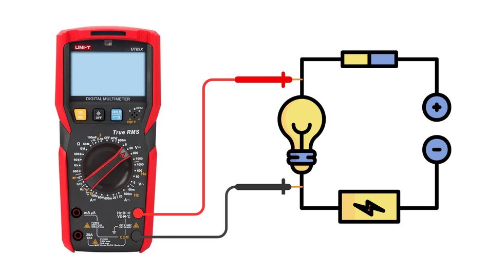
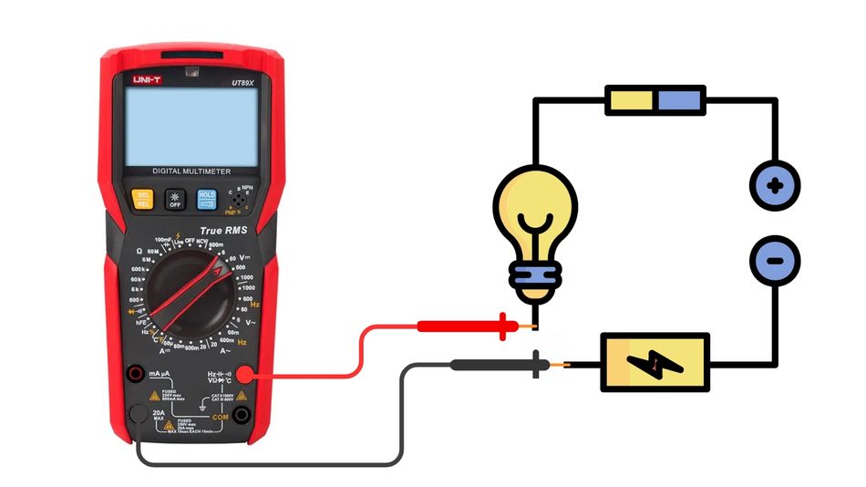
In-Line Current Measurement and Shunt Resistors
To measure current, the multimeter must be inserted in series with the part of the circuit under test. Most DMMs use an internal shunt resistor. The meter measures the voltage drop across this known resistor and calculates current via Ohm's law.
The downside is burden voltage, the voltage dropped across the shunt, which reduces the voltage available to the circuit. For example, on the Fluke 87V, the burden voltage in the 400 mA range is approximately 1.8 mV per milliamp. [2] Thus measuring 1 mA introduces a 1.8 mV drop, while measuring 300 mA introduces about 0.54 V. In a 3 V battery circuit drawing 100 mA, this 0.18 V drop represents a 6% reduction, potentially altering circuit behaviour.
To minimise burden voltage:
Use the highest current range that offers sufficient resolution, since higher ranges use lower-value shunt resistors.
Consider using a current clamp accessory (Hall-effect or Rogowski coil) that measures current via magnetic fields without inserting a resistor.
Where precision is essential, insert a known four-terminal shunt resistor in the circuit and measure the voltage across it with the DMM; calculate current externally.
Using Current Clamps and Sensors
Clamp meters measure AC or DC current by sensing the magnetic field surrounding a conductor. They introduce negligible burden voltage and are ideal for measuring high current or inaccessible conductors. Engineers working on three-phase motors, automotive alternators or industrial feeders should opt for True-RMS clamp meters for accurate results with non-sinusoidal currents.
Milliamps and Microamps Ranges
Digital multimeters typically provide milliamp ranges (e.g., 40 mA or 400 mA) and sometimes microamp ranges (e.g., 400 uA) for low-current measurements. [5] Always move the red probe to the mA/uA jack and select the appropriate range. Blowing the mA fuse is common when inadvertently placing the meter in series with high current; fuses are there to protect the shunt and the user. [3] If high currents are expected, use the 10 A jack and range instead. Replace blown fuses only with those specified by the manufacturer.
Recommended Reading: How to Test a MOSFET: Theoretical Basics and Practical Step-by-Step Guide
Measuring Resistance and Continuity
Two-Wire Resistance Measurement
Resistance measurements use Ohm's law: R = V/I. The ohmmeter forces a known current through the device under test, measures the resulting voltage drop and computes the resistance. In a standard 2-wire measurement, the current source and voltmeter share the same leads, so the measurement includes the resistance of the test leads. For resistances above a few ohms, lead resistance (typically a fraction of an ohm) is negligible.
To obtain consistent readings:
De-energise the circuit and discharge any capacitors.
Select the Ω function and connect the probes across the component.
Wait for the reading to stabilise. Auto-ranging meters may briefly display a higher range before settling.
Kelvin Four-Wire Measurement for Low Resistance
When measuring very low resistance (wiring harnesses, contact resistances or current-sense resistors), lead resistance can dominate the reading. A four-wire (Kelvin) measurement separates the force leads from the sense leads. Two leads carry the test current, while two separate leads measure the voltage drop across the device; this eliminates the voltage drop due to the leads themselves.
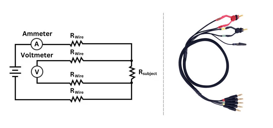
The four-wire instruments can measure resistances down to 1 mΩ (0.001 Ω) with high accuracy. [4]
Benefit | Explanation |
Eliminates Lead Resistance | The voltmeter senses voltage directly across the device, excluding lead and contact resistance |
Enables Low-Resistance Measurements | Instruments using Kelvin connections achieve accuracy down to milliohms |
Improved Consistency | Four-wire measurements reduce variability caused by contact pressure and connector wear |
The trade-offs include increased complexity, doubled connection points and longer measurement time. Four-wire measurement is recommended for characterising current-shunt resistors, measuring motor winding resistance and verifying low-resistance connections in power distribution.
Continuity Testing and Beeper Function
Continuity mode uses the resistance function with an audible beep when the resistance is below a threshold (often 20 to 50 Ω). This function is invaluable for quick checks of PCB traces, wiring harnesses or verifying that a fuse is intact. For high-reliability applications, use continuity mode to verify that all connectors and solder joints are properly connected before powering a system.
Special Measurement Functions
Diode and Transistor Testing
Diode test mode applies a small current to the diode and displays the forward voltage. Typical forward voltages are 0.6 to 0.7 V for silicon diodes and 0.2 to 0.3 V for Schottky diodes. Some multimeters also provide a transistor hFE function, though engineers designing modern circuits often use curve tracers or dedicated testers instead.
Capacitance and Inductance
Capacitance measurement involves charging the capacitor with a known current and timing the voltage rise, then calculating capacitance from C = I x Δt / ΔV. Capacitance functions are convenient for verifying decoupling capacitors on a PCB or testing electrolytic capacitors for aging. Ensure the capacitor is discharged before measurement. Bench LCR meters offer higher accuracy and can measure inductance, Q factor and dissipation factor.
Frequency and Duty Cycle
Many DMMs offer frequency measurement for signals up to several hundred kilohertz. Accurate frequency measurement requires a clean, high-amplitude signal; noise and distortion can cause false readings. Duty-cycle measurement reports the percentage of time that a pulse waveform is high; this is useful when debugging PWM circuits and switching power supplies.
Temperature Measurement
Some multimeters include thermocouple inputs or use external temperature probes. When measuring temperature, set the meter to the appropriate C/F mode and use the supplied thermocouple. Thermocouple readings require cold-junction compensation; consult the meter manual for calibration procedures.
Recommended Reading: Forward Bias, Reverse Bias and their effects on Diodes
Troubleshooting and Practical Tips
Safe Measurement Practices
Verify the Integrity of Meter Before Use: Inspect the case, test leads, probe tips and fuses. Do not use a damaged meter. Replace worn test leads with ones that match the meter's category rating.
De-Energise Circuits whenever Possible: When measuring resistance, continuity or diode voltage, ensure the circuit is powered off, and capacitors are discharged.
For Live Measurements: Use only one hand to avoid current passing through the heart and keep the other hand away from the ground.
Start with the Highest Range: When measuring an unknown voltage or current, begin with the highest range to avoid overload. Then switch to lower ranges for higher resolution.
Observe Polarity and Connections: Always connect the black probe to COM and the red probe to the correct input jack (VΩ, mA or A). Disconnect the red lead from the high-current jack, then return it to the VΩ jack when finished measuring current, to avoid accidentally shorting a voltage source.
Measuring Power Supplies and Voltage Drops
When troubleshooting a power supply, measure the input and output voltages under load. Compare readings to the specified voltage setting. Use the voltage drop feature to check voltage drop across conductors or connectors; a large voltage drop indicates high resistance or a poor connection. In automotive circuits, measure voltage at the battery, alternator and loads to identify failing components.
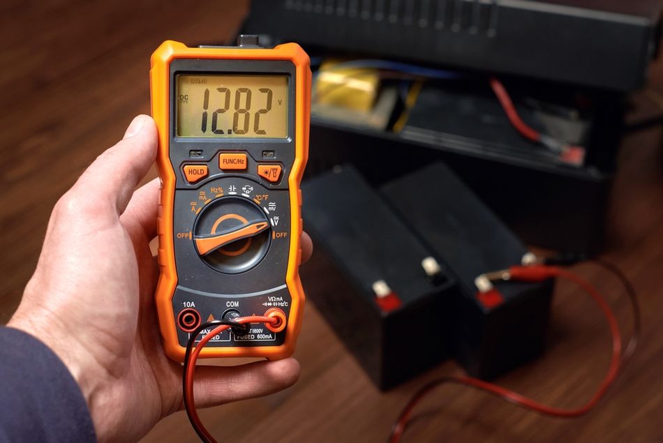
Testing Batteries and Wall Outlets
To test batteries, set the meter to DC volts and measure across the terminals. Compare the reading to the nominal voltage (e.g., 1.5 V for AA cells, 12.6 V for fully charged 12 V lead-acid batteries).
For wall outlets (mains), set the meter to AC volts and ensure the CAT rating is appropriate. Use a plug-in tester when verifying that receptacles are wired correctly; do not insert bare probes into outlets unless trained and using a CAT III or CAT IV rated meter.
Measuring Arduino and Hobbyist Circuits
Arduino and microcontroller boards often operate at 5 V or 3.3 V. Use a high-impedance digital multimeter to measure supply rails and analog inputs so the measurement does not affect operation. When measuring current consumption, insert the meter in series with the positive supply lead; be mindful of burden voltage. For long-term data logging, consider using a shunt resistor and an amplifier to monitor current with minimal voltage drop.
Choosing the Right Multimeter
Engineers should match the multimeter features to their application:
Feature | Engineering Considerations | Example Specification |
Accuracy and Resolution | High-resolution bench DMMs provide 5.5 to 6.5 digits and accuracies better than 0.01%. Handheld meters typically offer 3.5 to 4.5 digits and 0.5% to 0.1% accuracy. | A 6.5-digit benchtop multimeter may specify plus or minus 0.0035% accuracy on DC voltage. |
Input Impedance | For minimal circuit loading, look for 10 MΩ or higher input. Dual-impedance meters offer LoZ for ghost-voltage elimination and HiZ for sensitive circuits. | High-Z: 10 MΩ; Low-Z: 2 kΩ to 100 kΩ |
True RMS Capability | Essential when measuring distorted AC waveforms produced by modern power supplies and drives. | True RMS meter measures accurate RMS up to specified frequency and crest factor. |
Current Ranges and Burden Voltage | Evaluate the burden voltage per milliamp of current on each range. High-current ranges have lower shunt resistance and lower burden voltage. | 400 mA range: 1.8 mV/mA burden; 10 A range: 0.01 mV/mA. |
Safety Ratings (CAT) | Choose CAT III or CAT IV for industrial and service entrance work. Ensure fuses, leads and meter share the same rating. | CAT III 600 V; CAT IV 300 V. |
Special Functions | If you need capacitance, frequency, temperature, connectivity (Bluetooth, logging), or 4-wire resistance measurement, select models that include these features. | 4-wire measurement resolution down to 1 mΩ |
When selecting a multimeter for automotive diagnostics, look for a high-current range (up to 20 A), robust construction and a CAT III rating. For digital design, prioritise input impedance, True RMS capability, microamp measurement and data logging. Laboratory bench meters provide the highest accuracy and often offer Kelvin measurement built in.
Conclusion
Multimeter is a precision instrument essential for engineering applications. Accurate measurements rely on core principles such as Ohm’s law, RMS calculations, and voltage behavior. Engineers must understand factors like input impedance, burden voltage, and measurement categories to ensure reliable results. Techniques such as four-wire Kelvin measurement improve low-resistance accuracy, while High-Z and Low-Z modes address circuit loading and ghost voltages.
With increasingly complex electronic systems, multimeters continue to evolve with enhanced accuracy and analytical capabilities. However, mastering fundamental measurement techniques remains critical. A strong understanding of both the instrument and its limitations enables engineers to diagnose faults effectively, validate system performance, and maintain operational safety.
Frequently Asked Questions (FAQs)
Q1. Why does my digital multimeter show a voltage when nothing is connected?
A. Ghost voltages arise when the high input impedance of the meter allows stray electric fields or capacitive coupling to induce a small voltage reading. Low-impedance meters (2 kΩ to 100 kΩ) bleed off ghost charges. Many modern DMMs include a Low Z or Auto-V/LoZ mode that presents a low impedance to the circuit.
Q2. How do I choose between auto-ranging and manual ranges?
A. Auto-ranging simplifies measurements when you do not know the approximate value. Manual ranges provide stability when monitoring slowly varying signals or when the auto range may bounce. For high-current measurements, starting in the highest range prevents overload.
Q3. Can I measure mains voltage with any multimeter?
A. Only use multimeters rated for the appropriate CAT category and voltage. For typical wall outlet measurements, choose a meter rated CAT II or higher for the voltage involved. Never use hobbyist meters on industrial circuits requiring CAT III or CAT IV ratings.
Q4. Why do my current measurements sometimes alter circuit operation?
A. In-line current measurements insert the meter's shunt resistor into the circuit, causing a voltage drop (burden voltage). On the Fluke 87V, for example, this is approximately 1.8 mV/mA on the 400 mA range. On low-voltage circuits, this drop can reduce the supply voltage and change behaviour. Use a higher current range, an external shunt or a clamp meter to minimise burden.
Q5. When should I use a four-wire resistance measurement?
A. Use Kelvin connections when measuring resistances below about 1 Ω, such as current-sense resistors, motor windings or contacts. Four-wire measurement separates force and sense leads, removing lead resistance and enabling milliohm-level accuracy.
Q6. Do I need a true RMS meter for DC measurements?
A. True RMS capability applies only to AC and mixed signals. For pure Direct Current measurements, average-responding and true RMS meters yield the same result. However, many modern meters incorporate true RMS capability for completeness.
References
[1] Megger. The Measurement Category (CAT) rating: Why it Matters? [Cited 2026 March 25]; Available at: Link
[2] Fluke. Can You Live with the Burden? [Cited 2026 March 25]; Available at: Link
[3] Keysight. How to Check a Fuse With a Multimeter [Cited 2026 March 25]; Available at: Link
[4] Keysight. How to Measure Resistance Using Four-Wire Measurement [Cited 2026 March 25]; Available at: Link
[5] National Instruments. Digital Multimeter (DMM) Measurement Fundamentals [Cited 2026 March 25]; Available at: Link
in this article
1. Key Takeaways2. Introduction3. Fundamentals of Multimeters4. Measuring Voltage5. Measuring Current6. Measuring Resistance and Continuity7. Special Measurement Functions8. Troubleshooting and Practical Tips9. Choosing the Right Multimeter10. Conclusion11. Frequently Asked Questions (FAQs)12. References