How to Test a MOSFET: Theoretical Basics and Practical Step-by-Step Guide
Learn the step-by-step process of testing MOSFET transistors using a digital multimeter and simple circuits. This comprehensive guide covers MOSFET fundamentals, diagnostic techniques, and practical tips for engineers and electronics students.

11 Jul, 2025. 21 minutes read
Testing MOSFET Transistors using a Digital Multimeter
Introduction
Metal-Oxide-Semiconductor Field-Effect Transistors (MOSFETs) are essential in modern electronics, serving as efficient switches and power-handling devices. When a circuit malfunctions, a MOSFET is often a suspect – knowing how to test a MOSFET is therefore a vital skill for hardware engineers and students. Testing a MOSFET involves both understanding its theory of operation and performing practical checks with basic instruments.
In this article, we’ll explore how to test a MOSFET using a digital multimeter and simple test circuits, covering both the theoretical concepts and practical implementations step-by-step. By the end, you’ll be able to confidently diagnose a MOSFET to determine if it’s healthy or has failed, using techniques that align with industry best practices. Still, curious about, how to test a MOSFET? Let’s start with the basics of MOSFET!
Understanding MOSFET Basics
MOSFETs are three-terminal semiconductor devices (Gate, Drain, Source) that operate as voltage-controlled switches. They are widely used in power supply, amplifier, and digital switching applications. Unlike a BJT, which is current-driven, the operation of MOSFET depends on the gate-to-source voltage (VGS). When a sufficient VGS is applied, an N-channel MOSFET enters conduction mode, allowing current to flow from drain to source. For P-channel MOSFETs, current flows from source to drain when a negative VGS is applied.

A defining characteristic of the MOSFET gate is its electrical insulation, created by a thin oxide layer, which gives it capacitive behavior. This means that virtually no steady-state current flows into the gate. Consequently, a healthy MOSFET will show an open circuit or very high resistance when you check the gate terminal against the source or drain using a multimeter.
One key feature of power MOSFETs is the intrinsic body diode. Due to the construction of transistors, there’s a built-in p-n junction diode between the source and drain terminals. In N-channel MOSFETs, this diode is typically oriented from source to drain (conducting current when the source is at a higher potential than the drain). In P-channel MOSFETs, the diode direction is reversed (from drain to source).
This body diode conducts when the MOSFET is reverse-biased in the off state, exhibiting a forward voltage drop similar to that of a standard diode (~0.6–0.7 V for silicon devices). [1] The presence of the body diode is crucial for understanding specific measurements when testing a MOSFET with a multimeter.
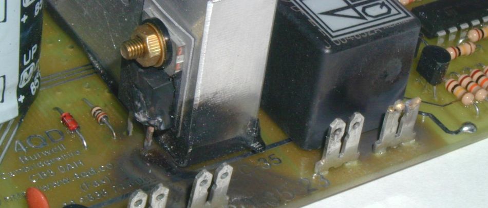
MOSFET Failure Modes: MOSFETs, especially power MOSFETs, tend to fail in a way that shorts internally. Excessive current or voltage can punch through the silicon, often resulting in the drain, source, and sometimes gate being electrically shorted together. It’s common to find a failed MOSFET with near-zero resistance between drain and source. Less frequently, a MOSFET may fail “open” (no conduction even when gate is driven) or develop leakage (a degraded gate oxide causing current between gate and channel). Recognizing these symptoms is critical before proceeding to detailed diagnostics using a digital multimeter, tester, or test circuit.
Recommended Reading: How Do MOSFETs Work: Comprehensive Technical Guide for Engineers (2025)
Why and When to Test a MOSFET?
If you suspect a MOSFET in your circuit is causing problems, such as a power supply that blew out or a motor driver that stopped working, testing the MOSFET can confirm if it’s defective. The troubleshooting scenarios often include checking MOSFETs when a device blows a fuse, runs excessively hot, or a circuit output is stuck on or off. Testing is also helpful for incoming inspection of components or salvaging parts from old boards.
Key reasons to test a MOSFET include:
Suspected Failure: The circuit isn’t functioning as expected, and you need to pinpoint if the MOSFET is at fault. Since MOSFETs usually fail short (connecting drain to source in a fault), a quick continuity test can save time before delving deeper into circuit analysis.
After Stress Events: If a MOSFET experienced an over-current or over-voltage event (e.g., a short circuit load or electrostatic discharge), it’s wise to test it. Even if it isn’t burnt, its characteristics might be altered.
Prototyping and Repairs: When building a prototype or repairing equipment, you might test MOSFETs before installation to ensure the parts are good. This is especially important if using salvaged or unmarked transistors, verifying pin configuration and basic function is essential.
By systematically testing a MOSFET, you can avoid powering up a circuit with a bad transistor and prevent further damage. Next, we’ll outline the tools and precautions needed to test a MOSFET safely and accurately.
Tools and Safety for MOSFET Testing
Before beginning the testing process, it’s crucial to gather the appropriate tools and follow certain key safety practices.
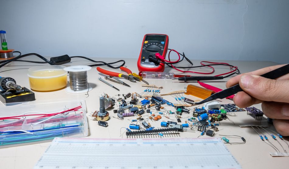
Essential Tools
Digital Multimeter (DMM): A DMM with a diode test or continuity mode is the primary tool for MOSFET testing. This mode will allow you to measure diode forward voltage and check for shorts.
MOSFET Datasheet: Having the datasheet of the transistor on hand is essential for identifying the pin layout (Gate, Drain, Source) and understanding expected parameters. If the MOSFET is on a circuit board, the silkscreen or schematic of the board can also help identify terminals.
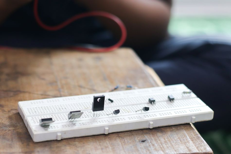
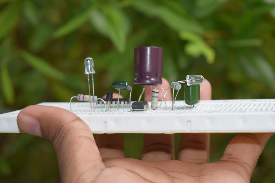
Breadboard or Test Fixture (Optional): For functional tests, a simple breadboard setup or a dedicated MOSFET tester jig can be useful, but it’s not strictly required for basic tests.
Power Source for Functional Test (Optional): A small bench power supply or battery (along with a resistor and LED or other load) can help verify the switching operation of the MOSFET under a low-voltage load.
Safety and Handling Precautions
Power Down and Isolate: Always remove power from the circuit and, if possible, take the MOSFET out of the circuit before testing. Testing in-circuit can be misleading and even risky. Other components can affect your multimeter readings, and a charged capacitor could unexpectedly shock the MOSFET (or you). The only sure way to test a MOSFET is often to remove it from the circuit, since in-circuit influences can skew the readings.
Discharge Gate Capacitance: MOSFET gates can hold a charge (like a capacitor) that might keep the transistor internally on or off. Before each test, discharge the gate of the MOSFET by shorting the gate to the source (and drain, to be extra sure) momentarily. This “resets” the MOSFET to a known off state.
ESD Protection: The gate oxide of MOSFET is very sensitive to static electricity. Use proper ESD precautions – at minimum, ground yourself or touch a grounded metal surface before handling the MOSFET. Avoid shuffling your feet on carpet on dry days, etc. Holding the device by its edges and not directly touching the gate pin can also reduce risk.
Avoid Body Contact During Measurement: When using the multimeter, keep your fingers away from the metal probes and MOSFET leads. Your body can introduce stray voltages or capacitances that affect the readings. For example, accidentally injecting charge into the gate via your body could turn the MOSFET on during the test. It’s best to lay the MOSFET on a non-conductive surface (e.g., a wooden table) and use alligator-clip leads or steady hands on the insulated probe parts while measuring. As one expert notes, touching the device leads during testing may alter the gate charge and thus affect your measurements.
With the right tools in place and safety protocols observed, you’re ready to begin testing. The procedure that follows focuses on the most common type: the N-channel enhancement-mode MOSFET. The variations for P-channel types will be noted accordingly.
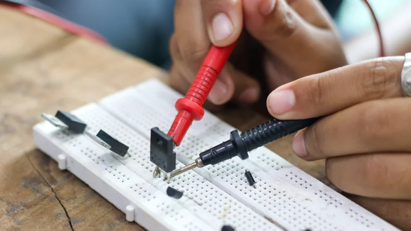
Step-by-Step: How to Test a MOSFET with a Multimeter
Testing a MOSFET using a DMM involves a series of checks. We will go through the identification process, checking for shorts, using the diode test to locate the body diode, and then actually toggle the MOSFET on and off using the output of the meter.

It is necessary to ensure that your MOSFET is removed from the circuit board (or at least completely isolated) for these tests to yield reliable results.
1. Identify the Terminals and Initial Condition
First, determine the pin configuration of the MOSFET – which lead is Gate (G), Drain (D), and Source (S)? For a known part, refer to the datasheet or any markings on the package. If the pin layout is unknown, you can use the diode test in your multimeter to identify them by locating the body diode (explained in the next step). For example, when you find two pins that show a diode drop of about 0.6–0.7 V in one direction, you’ve likely identified the source and drain of an N-channel MOSFET (with the source being the positive lead side for that reading).
Discharge the MOSFET: Before testing, ensure any built-up charge on the gate is removed. Simply touch or connect the gate and source pins (you can also include the drain pin in this short to be thorough). This will discharge any residual charge in the gate capacitance and place the MOSFET in a known “off” state. [2]
Now, with the DMM in diode test mode, do a quick sanity check on the gate: touch the red (positive) probe to the gate and the black (negative) probe to the source. The multimeter should not beep or show any significant conduction – it should read as an open circuit. This is expected because the gate is insulated; any reading here could mean a gate-to-source short. For instance, one testing guide suggests that touching Gate with the meter’s black lead and Source with the red lead should give an open circuit reading, and anything else indicates a short between Gate and Source. If you do read a short (zero ohms or continuity tone) between gate and source (or gate and drain), the gate oxide of the MOSFET is blown – the device is bad and further testing is pointless until you replace it.
By this stage, we have identified G, S, D (or at least have a way to identify D and S via the diode test next) and confirmed there’s no immediate short on the gate. The MOSFET is discharged and ready for the next steps.
2. Check for Drain-Source Short (Continuity Test)
One of the quickest ways to spot a failed MOSFET is to check if its drain and source are shorted together. With the MOSFET still “off” (gate discharged), do the following:
Continuity/Resistance Check: Keep the DMM in continuity mode (often the same as diode mode, or a separate setting that beeps on low resistance). Place the black probe on the source and the red probe on the drain (for an N-channel device). Observe the reading or beep. Then swap the probes (red on source, black on drain) and check again.
For a good MOSFET in the off state, neither direction should show continuity – you should see an open circuit in both polarities when no gate voltage is applied. A faulty MOSFET, however, may show a short in one or both directions. If your multimeter beeps (indicating near-zero resistance) in either orientation during this test, it means the drain-source channel is shorted even with the device off, which is a clear sign of a failed MOSFET. Stop the test at this point, because a drain-to-source short is usually definitive evidence of a bad transistor.
Continuity in both directions may also occur if the MOSFET is internally on (perhaps due to residual charge) or if it’s a depletion-mode device (rare). But in our setup, we discharged the gate, so an unexpected continuity reading strongly suggests a bad MOSFET. Power MOSFETs commonly fail by shorting out internally, so this step is a high-yield diagnostic. If no short is detected, we proceed.
3. Perform the Body Diode Test
Next, we will use the diode function of the multimeter to find and test the body diode of a MOSFET. This not only confirms the polarity of a device (N vs P type) and which pins are drain/source, but also further checks for any internal damage.
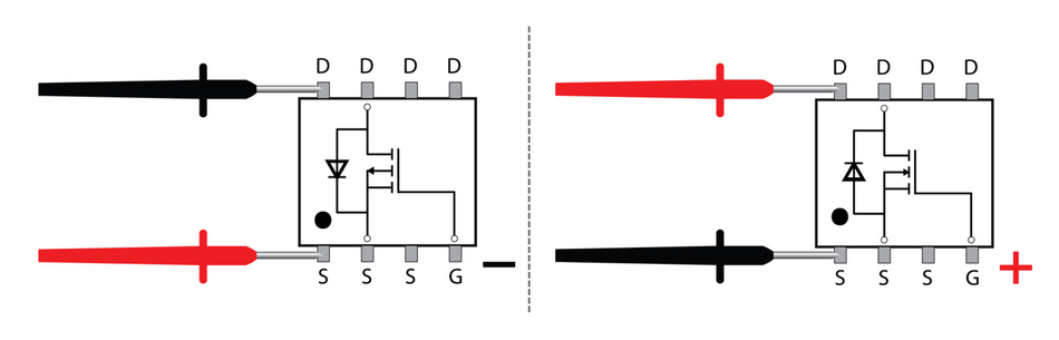
For N-Channel MOSFET: Keep the black probe on the drain and the red probe on the source (this reverse-biases the body diode). In this orientation, a healthy MOSFET that is off will show an open circuit (no conduction) because the body diode is reverse-biased and the channel is off. Now swap the probes: put the red on drain and black on source, which forward-biases the body diode (anode at drain for an N-channel device). The multimeter should show a forward voltage in the ballpark of 0.5 to 0.7 volts (some power MOSFET body diodes might read slightly lower, like 0.2–0.3 V, depending on test current, but generally a diode drop is observed). This reading is the intrinsic diode conducting between the source and drain of your MOSFET.
For example, one reference notes that in diode mode, you should get one realistic diode forward-voltage reading among the six possible pin pair combinations – that will be the body diode between source and drain. Identifying this confirms which pin is source (the one connected to the red probe when the diode showed forward bias) and which is drain (connected to the black probe in that test) for an N-channel MOSFET.For P-Channel MOSFET: The body diode is oriented opposite. So in the above test, a P-channel device would show an open circuit when red is on the drain and black on the source, and a forward diode drop when red is on source and black on drain. In other words, you’d get ~0.6 V with red on the source of a P-channel and black on its drain. We will revisit P-channel specifics later, but keep this in mind if you happen to be testing one: the diode test works the same way, but with the polarity flipped.
What do these diode results tell us? A healthy MOSFET should exhibit one and only one diode forward drop between two of its terminals (the source and drain). If you see a diode-like reading between gate and source or gate and drain, that’s abnormal (MOSFETs don’t have any diode from the gate). That could indicate you’re dealing with a different device (like an IGBT or JFET) or the MOSFET is damaged.
If no diode forward voltage is seen at all (all combinations read open), there might be two possibilities:
(1) The body diode of MOSFET is damaged, or it’s an unusual MOSFET without a body diode (which is rare in discrete MOSFETs – virtually all have it, except perhaps some GaN transistors or complex ICs).
(2) You might have misidentified the pins. Re-check the pin orientation and ensure good contact with the probes. If indeed the body diode is gone (i.e., it reads open both ways when it should show a drop one way), the MOSFET might be blown in a way that the diode junction ruptured – that’s a defective part.
So far, we’ve checked that:
The gate isn’t shorted
Drain-Source isn’t shorted (when off)
The body diode behaves normally (uni-directional conduction)
If all these pass, the MOSFET is likely not catastrophically failed. The final verification is to see if we can turn it on and off using a simulated gate signal.
4. Gate Charge Test – Turning the MOSFET On
Now we attempt to activate the channel of MOSFET! Normally, this is done by applying the appropriate gate-to-source voltage (VGS). We can use the diode test mode of a multimeter itself to provide a small voltage to the gate. Most DMMs in diode mode output a few volts (typically around 2.5 V to 3 V) through the leads. [3] This is often enough to charge the gate of many MOSFETs to or beyond the threshold voltage needed to start conduction.
To turn on an N-channel MOSFET using the multimeter:
Keep the black (–) probe on the source, and touch the red (+) probe to the gate pin. The meter will attempt to measure a “diode” between the gate and source. The reading should remain an open circuit (there’s no real diode between gate and source in a healthy MOSFET) – this also double-checks the gate insulation one more time while the gate is being charged. The key is that during this brief contact, the meter is applying ~2–3 volts between the gate and source.
Remove the red probe from the gate without touching the gate with your fingers or allowing it to discharge. The gate of your MOSFET is now charged up (for an N-channel, it has a positive charge relative to the source). This should have put the transistor in the “on” state, or at least partially on.
Now quickly proceed to the subsequent measurement while the gate is holding the charge (you usually have a few minutes before it leaks off):
Check the Drain-Source conduction: With the gate now charged (MOSFET should be on), measure the resistance or diode drop between drain and source again. This time, for an N-channel, put the red probe on the drain and black on the source. If the MOSFET turned on, the multimeter should show a very low reading – often it may beep as if there is a short, or show only a few millivolts of drop. This indicates the channel is conducting.
In fact, in this on-state, you’ll likely get a low reading in both directions (swap red and black between drain and source, and it still shows low resistance) because a fully enhanced MOSFET conducts in either direction between drain and source (it behaves like a low-value resistor). Seeing a near-zero reading now, when previously it was open, is evidence that the transistor channel of a MOSFET is functioning.
Finally, to complete the test, discharge the gate again by shorting the gate to source (to turn it off). If you need to repeat or demonstrate it again, you can cycle through the steps: ensure off, then charge gate, then check on-state. Some power MOSFETs require more than 3V to turn on, so you may need to manually apply a higher gate voltage using a battery and resistor.
A healthy N-channel MOSFET should pass these checks:
No shorts between gate-source or drain-source
Visible body diode (source to drain)
Clear transition from open circuit to low resistance when the gate is charged
If any of these are missing, especially if the device always reads short circuit or never turns on, the transistor is likely faulty. This concludes the core multimeter method for testing a MOSFET.
Recommended Reading: JFET vs MOSFET: A Comprehensive Engineering Analysis and Selection Guide
Basic Functional Testing with a Simple Circuit
The multimeter method above tests the basic integrity of a MOSFET. For additional confidence, especially if you plan to use the MOSFET in a circuit, you can perform a quick functional test by actually operating the transistor in a simple circuit.
This can reveal if the MOSFET switches a load on and off as expected.
Simple LED Test Circuit
One widely used functional setup is an LED-based test circuit! For an N-channel MOSFET, connect the source terminal to ground. Place an LED and a resistor in series from the positive supply (5V or 12V) to the drain. Add a gate pull-down resistor (e.g., 10kΩ) from gate to ground to keep the transistor off when idle. To test conduction, momentarily apply a positive gate voltage—for example, by connecting the gate to V+ using a wire or pushbutton. If the MOSFET is functional, it will turn on, allowing current to flow from drain to source, lighting the LED. Releasing the gate voltage should turn off the device and extinguish the LED.
For P-channel MOSFETs, reverse the polarity of the circuit: connect the source to V+, drain to the LED-resistor pair going to ground, and use a pull-up resistor from gate to source. Apply a low voltage to the gate (e.g., via pushbutton to ground) to turn it on. The LED should behave similarly—on with gate drive, off when released.
This method can be developed into a reusable MOSFET tester jig with a socket, power rail, LED, resistors, and a switch. If the LED lights only when the button is pressed, the MOSFET is working. If it’s always on (indicating a short circuit) or never lights (indicating an open circuit or gate fault), the device is defective.
Optional Quantified Testing
You can enhance this setup with a multimeter to measure current flow or voltage drop across the MOSFET during operation. This helps detect issues like excessive RDS(on) or weak switching, though such metrics often require lab-grade equipment for precise values.
Gate Threshold Testing
To estimate the threshold voltage, gradually apply increasing VGS using a potentiometer or variable power supply and observe when the LED begins to glow. While this analog method doesn’t provide precise values, it helps confirm that the MOSFET starts to conduct within the expected range.
In conclusion, combining diode mode testing with this simple functional test circuit provides a reliable method for evaluating the condition of the MOSFET before installation.
Interpreting Test Results
After performing the above tests, you’ll have a set of observations. Here’s how to interpret them:
All Tests Pass
If the MOSFET shows no short circuit between gate-source or drain-source, reveals a proper body diode drop (~0.6–0.7 V in one direction), and turns on when gate voltage is applied (drain-source becomes low resistance), the device is considered good. This means the gate oxide is intact, the channel conducts properly, and the transistor behaves as expected under low-voltage testing. However, note that this doesn't guarantee full performance under high-current or high-voltage loads. Still, a passing result strongly indicates a usable component for most applications.
Drain-Source Short (Failed)
If your digital multimeter shows near-zero resistance between drain and source even without applying gate voltage, the MOSFET has likely suffered internal failure. This usually results from electrical overstress, where the silicon structure melts, creating a permanent conduction path. In real circuits, this often causes blown fuses, shorted power rails, or PCB damage. Replace the MOSFET immediately, this is a textbook test failure.
Gate Short or Leak (Failed)
If you found any continuity between the gate and source or gate and drain, the gate oxide is ruptured. The MOSFET cannot be trusted because the gate can no longer control the channel properly. Sometimes, a gate leak can be subtle. Any significant conduction path from gate to others is a fail condition for the integrity of a MOSFET. In a circuit, a MOSFET with a leaky gate might partially turn on or off erratically, so it should be discarded.
No Body Diode Reading (Suspicious/Failed)
If you expected a body diode but didn’t get any forward drop, double-check the pins. If the diode was present and now reads open circuit, it could indicate a catastrophic failure. Since the body diode is an inherent part of the silicon in a MOSFET, its absence typically points to major internal damage. Treat the device as failed.
Won’t Turn On with Gate Charge (Inconclusive or Failed)
If the MOSFET doesn’t show any drain-source conduction after charging the gate, consider:
The threshold voltage (VGS(th)) may be too high for the diode mode of your meter (usually 2.5–3 V). Some power MOSFETs require 5–10 V to fully turn on.
The channel could be damaged internally, preventing conduction even if the gate capacitance and diode are intact.
You might not have applied enough gate voltage, or the charge didn’t hold due to leakage or test error.
Try a higher gate voltage using an external power source through a resistor. If no conduction occurs even then, the MOSFET is non-functional and should be replaced.
In-Circuit Testing Limitations
If you’re testing the MOSFET in-circuit, be cautious. Parallel paths, diodes, or other components may skew the readings. For example, a diode drop seen between drain-source might not be the body diode, but another device in parallel. If readings are inconsistent or unclear, remove the MOSFET from the circuit board and test it isolated.
In summary, a good MOSFET will behave like an off switch (open circuit) with a diode in one direction when off, and like a closed switch (low resistance) when appropriately turned on. A bad MOSFET often shows up as a shorted switch (conducting all the time) or a switch that never conducts at all. Any gate anomaly is also a definite red flag. By systematically checking each aspect, you can diagnose the condition of any MOSFET with a high degree of certainty.
Testing P-Channel vs. N-Channel MOSFETs
So far, we illustrated the procedure with N-channel MOSFETs, which are the most common in power electronics (e.g., used in low-side switches, buck converters, etc.).
P-channel MOSFETs, used often for high-side switches or certain analog switches, can be tested in a very similar manner – but you must reverse the polarities for the diode and gate tests because of their complementary nature.
Body Diode Orientation
Every MOSFET includes an intrinsic body diode, which serves as a clue to pin identification and device health. In an N-channel MOSFET, the body diode conducts from source to drain. In contrast, a P-channel MOSFET has its body diode oriented from drain to source.
To identify this with a diode test:
Place the red probe on the drain and the black probe on the source.
If the body diode is intact, the digital multimeter should show a forward voltage drop (~0.6 V).
Reversing the leads should result in an open circuit.
This reversal helps identify polarity: for P-channel devices, the source terminal is more positive than the drain, which is the opposite of the N-channel convention.
Gate Charging for P-Channel Devices
A P-channel MOSFET turns on when the gate voltage is lower than the source (i.e., a negative VGS). To simulate this with your multimeter:
Connect the red probe to the source.
Briefly touch the black probe to the gate.
This injects a small negative charge to the gate relative to the source, causing the MOSFET channel to enhance and prepare for conduction. Be sure to discharge the gate beforehand by shorting it to the source.
Drain-Source Conduction Check
With the gate charged, test for drain-source conduction:
Place the black probe on the drain and the red probe on the source.
A low resistance or continuity beep indicates the P-channel MOSFET has successfully turned on.
Just as with N-channel types, you may notice low resistance in both directions once the channel is fully enhanced. This confirms the conduction state.
Resetting the Gate
After testing, return the MOSFET to its default off state by discharging the gate. For a P-channel, this means restoring the gate voltage to match the source terminal by shorting gate to source.
Summary of Polarity Reversals
To simplify the process:
Where you used the red probe for gate charging on an N-channel, use the black probe for a P-channel.
Where you forward-biased the body diode with red on source in an N-channel, use red on drain for the P-channel.
Always reverse polarities mentally when switching between MOSFET types.
This mirroring can seem confusing at first, but remembering that the P-channel is the complement of the N-channel helps. Using the datasheet and device schematic can clarify pin configuration and threshold voltage expectations.
Example Identification Using Diode Mode
Suppose you're unsure of the pinout. Using diode mode, you place the red lead on pin 1 and black on pin 2, and measure ~0.6 V. If this were an N-channel, pin 1 would be the source. But since it’s a P-channel, pin 1 is the drain and pin 2 is the source. Then, charge the gate using red on the source (pin 2) and black on the gate (pin 3). To confirm conduction, test drain-to-source again—black on drain, red on source—and expect a low resistance if the device is functional.
Practical Tip
Many engineers memorize the N-channel test process and simply invert the probes for P-channel MOSFETs. This mental shortcut simplifies the task and produces reliable results. The multimeter only outputs current; it doesn’t care about MOSFET type, so understanding the direction of current flow and polarity is the key.
The bottom line: P-channel MOSFETs test similarly to N-channels; just be mindful of the opposite current/voltage directions required. The same failure indicators apply: any unexpected continuity between terminals is bad, it should have one body diode reading, and it should switch on when the gate is given the correct bias.
Recommended Reading: PMOS vs NMOS: Unraveling the Differences in Transistor Technology
Advanced Testing (Using Specialized Equipment)
The techniques covered so far use basic equipment and give a good indication of the health of a MOSFET.

However, if you need to dive deeper into the characteristics of any MOSFET (for design or verification purposes), there are advanced testing methods and tools:
Curve Tracer or Semiconductor Analyzer
Devices like curve tracers can sweep the voltage and current through a MOSFET and plot its transfer characteristics. This allows you to measure parameters like threshold voltage VGS(th) precisely, transconductance, on-resistance at various gate voltages, etc. These are more for lab characterization than everyday troubleshooting. If you have access to such equipment, you likely already know how to use it – for completeness, be aware that a curve tracer can definitively characterize a MOSFET beyond simply “good/bad.” For instance, measuring VGS(th) properly requires using a very low current so as not to heat the device and skew the threshold.
LCR-T4 Component Testers
In recent years, cheap transistor tester gadgets have become popular. These are microcontroller-based devices where you plug in a transistor (BJT, MOSFET, diode, etc.) [4] and it automatically identifies the type of device and its pin configuration and gives a rough readout of some parameters. Some engineers use these for quick checks. One such device (the MK-328 or similar) can detect FETs, identify which pins are gate, drain, source, and even give an approximate gate threshold voltage and gate capacitance. They are quite handy for sorting unknown transistors. However, note that these testers operate at very low currents and voltages, so they won’t fully test a MOSFET under real stress. They might tell you a MOSFET is “good” in terms of basic function, but not how it performs at 30 A and 100 V, for example.
Oscilloscope Measurements
If diagnosing a MOSFET within a high-speed switching circuit (like an SMPS), sometimes measuring the gate and drain waveforms in operation with an oscilloscope is the only way to see certain failures (e.g., slow switching due to gate charge issues or oscillations). This goes beyond simple testing – it’s part of circuit debugging. But if you suspect dynamic issues (the MOSFET only fails at high frequency or under load), an oscilloscope and current probe might be needed to catch that.
Thermal Testing
In power applications, a MOSFET might check out fine with a multimeter but run excessively hot under load, indicating high RDS(on), possibly due to damage. Measuring the on-resistance directly is tricky without proper equipment. But a comparative approach can be used: if you have two identical MOSFETs, one suspect and one new, you could run a controlled current through them and measure the voltage drop to estimate resistance. Significant deviation could mean the suspect MOSFET is degraded. Again, this is advanced and rarely done outside of validation testing.
For most engineering and educational purposes, the multimeter and simple functional tests we described are sufficient and reliable to determine if a MOSFET is functional. Advanced methods are available for thorough analysis, but they require more gear and expertise. If a MOSFET passes the basic tests, yet the circuit still misbehaves, your next step might be to swap in a new MOSFET anyway (to rule out any subtle issues) or investigate the surrounding circuitry with more sophisticated tools.
Recommended Reading: Next-generation MOSFET Technology Meets Demand for Strong Thermal Performance in Automotive Applications
Conclusion
Testing a MOSFET involves a combination of theory and practical measurement. By using a multimeter in diode test mode, it is easy to assess the health of a MOSFET through its body diode, check for shorts, and toggle it using gate charge. A good device should show no unintended continuity, a clear diode-like junction between drain-source, and switch cleanly with proper gate voltage. Faulty MOSFETs often conduct when they shouldn’t or fail to turn on altogether. It is better to consult the datasheet or tutorials for pinouts and threshold voltage details. With consistent practice, testing a MOSFET becomes easy, as it is an essential skill in troubleshooting and repair workflows, saving time and protecting your electronic circuits from future failures.
FAQ
Q1: Can I test a MOSFET without removing it from the circuit?
A. It’s not recommended! In-circuit components, such as resistors, diodes, or transformers, can affect readings. For accurate MOSFET testing, desolder one or more leads to isolate it. Multimeter results can be misleading due to parallel paths present on the circuit board.
Q2: What multimeter setting should I use to test a MOSFET?
A. Use Diode Test mode on a digital multimeter. It allows you to check the body diode, detect short circuits, and apply a small voltage to the gate. Some DMMs also include continuity mode for quick fault detection before more detailed analysis.
Q3: How do I know if a MOSFET is bad?
A. A bad MOSFET often shows a short circuit between the drain and source, or gate leakage. If it doesn’t turn on, lacks a visible voltage drop, or shows low resistance when it shouldn’t, it’s likely damaged and should be replaced.
Q4: What is the body diode of a MOSFET, and why does it matter in testing?
A. The body diode is built in between the source and drain. It helps identify polarity and pin orientation. Testing its presence confirms fundamental integrity. A missing or shorted body diode indicates a faulty MOSFET and invalidates normal conduction behavior.
Q5: Can a MOSFET pass these tests but still be faulty under load?
A. Yes. Some MOSFETs pass simple tests but fail under real power supply loads. Increased on-resistance, degraded threshold voltage, or gate capacitance issues may only appear under stress. Replace suspicious parts in critical systems even if they pass static checks.
Q6: My multimeter doesn’t have a diode test mode. Can I still test a MOSFET?
A. Yes, with limitations! Use ohms mode for basic checks. Some analog meters output enough voltage to reveal the body diode. For more accuracy, simulate gate charging with a battery or build a test circuit using an LED and a resistor.
References
[1] ResearchGate: Body Diode Reliability Investigation of SiC Power MOSFETs [Cited 2025 July 08] Available at: Link
[2] TI: Fundamentals of MOSFET and IGBT Gate Driver Circuits [Cited 2025 July 08] Available at: Link
[3] MDPI: On-State Voltage Measurement Circuit for Condition Monitoring of MOSFETs in Resonant Converters [Cited 2025 July 08] Available at: Link
[4] W3AFC: Transistor Testers [Cited 2025 July 08] Available at: Link
Listen to this article
in this article
1. Introduction2. Understanding MOSFET Basics3. Why and When to Test a MOSFET?4. Tools and Safety for MOSFET Testing5. Step-by-Step: How to Test a MOSFET with a Multimeter6. Basic Functional Testing with a Simple Circuit7. Interpreting Test ResultsTesting P-Channel vs. N-Channel MOSFETs9. Advanced Testing (Using Specialized Equipment)10. Conclusion11. FAQ12. References