ESP32 Pinout: A Comprehensive Guide for Engineers
This guide serves as a roadmap for engineers to navigate the intricacies of the ESP32 pinout, understand its significance, and explore its applications in modern engineering projects.

04 Jul, 2024. 19 minutes read
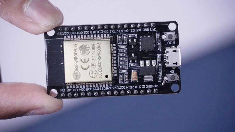
Espressif ESP32 series microcontroller module
Introduction
The ESP32 microcontroller has become a cornerstone in the world of embedded systems, known for its impressive combination of features, performance, and affordability. Developed by Espressif Systems, the ESP32 is a powerful tool widely adopted by engineers and developers across various fields. Its dual-core architecture, integrated Wi-Fi and Bluetooth capabilities, and extensive GPIO options make it an ideal choice for applications, ranging from simple IoT devices to complex industrial automation systems.
However, to unlock its true potential, engineers must navigate the intricacies of the ESP32 pinout. This includes General Purpose Input/Output (GPIO) pins for interfacing with various components, dedicated power supply pins, communication interfaces like SPI and I2C, and specialized functions for advanced control. Whether you are building a smart home device, a wearable gadget, or a robotics project, knowing the ins and outs of the ESP32 pinout will allow you to optimize performance and ensure reliability.
By understanding the ESP32 pinout, you'll be empowered to design creative and feature-rich embedded systems, pushing the boundaries of modern engineering. Let’s explore the architecture, discuss recent advancements, delve into real-world applications, and address common challenges. By the end of this guide, you will have a comprehensive understanding of how to effectively use the ESP32 pinout in your engineering projects.
Understanding the ESP32 Pinout Architecture
The ESP32 boasts a rich peripheral set for interfacing with various external components. It features 18 ADC channels for converting analog sensor signals to digital values. 4 SPI, 3 UART, and 2 I2C interfaces enable versatile serial communication with peripherals. Additionally, 16 PWM channels provide control over motors or LEDs with adjustable pulse widths. 2 DACs convert digital signals to analog outputs, while 2 I2S interfaces facilitate high-fidelity audio applications. Rounding out the options are 10 capacitive sensing GPIOs for touch-based controls. This comprehensive peripheral set empowers the ESP32 to handle diverse tasks in embedded system designs. [1]
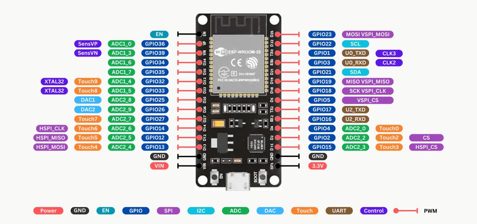
Central to its functionality is the pinout architecture, which defines how the microcontroller interfaces with external components and peripherals. Understanding this architecture is crucial for engineers looking to maximize the capabilities of ESP in their projects.
Significance of Each Pin Type
Within the ESP32, a diverse range of pins exist, each serving distinct purposes critical to the microcontroller's operation. These include:
1. General Purpose Input/Output (GPIO) Pins
GPIOs 34 to 39 are GPI input-only pins. These pins don’t have internal pull-up or pull-down resistors, and can’t be used as outputs. So, use GPIO34, GPIO35, GPIO36, and GPIO39 as input pins. Engineers can program GPIO pins to perform a wide range of functions, making them essential for tasks such as controlling LEDs, reading button states, and interfacing with digital sensors.
2. Analog-to-Digital Converter (ADC) Pins
The ESP32 has 18 x 12-bit ADC input channels. GPIO0, GPIO2, GPIO4, GPIO12, GPIO13, GPIO14, GPIO15, GPIO25, GPIO26, GPIO27, and GPIO32 - GPIO39 are the pins that can be used as ADC. These pins convert analog signals into digital data, vital for applications involving sensors that provide analog output, such as temperature sensors and light sensors.
3. Digital-to-Analog Converter (DAC) Pins
There are 2 x 8-bit DAC channels on the ESP32 to convert digital signals into analog outputs, essential for audio applications and scenarios requiring analog signal generation. GPIO25 and GPIO26 pins are used as DAC channels.
4. Universal Asynchronous Receiver/Transmitter (UART) Pins
UART pins facilitate serial communication, enabling the ESP32 to interface with devices like computers and other microcontrollers, crucial for debugging and programming. ESP32 can have multiple UART interfaces (UART0, UART1, UART2). GPIO1, GPIO3, GPIO16, and GPIO17 pins can be used as UART in the ESP-WROOM-32 chip.
5. Inter-Integrated Circuit (I2C) Pins
I2C pins allow for efficient communication with multiple slave devices using just two wires, which is particularly beneficial in complex projects with numerous components. I2C communication protocol uses two wires to share information. One, GPIO22 is used for the clock signal (SCL) and the other, GPIO21, is used to send and receive data (SDA).
6. Pulse-Width Modulation (PWM) Pins
The ESP32 LED PWM controller has 16 independent channels that can be configured to generate PWM signals with different properties. All pins that can act as outputs can be used as PWM pins, except GPIOs 34 to 39.
7. Serial Peripheral Interface (SPI) Pins
SPI pins support high-speed communication with peripherals, making them indispensable in data-intensive applications. The ESP32 has four SPI peripheral devices, called SPI0, SPI1, HSPI and VSPI. By default, the pin mapping for SPI is:
| SPI | MOSI | MISO | CLK | CS |
| VSPI | GPIO 23 | GPIO 19 | GPIO 23 | GPIO 5 |
| HSPI | GPIO 13 | GPIO 12 | GPIO 14 | GPIO 15 |
GPIO6 to GPIO9, GPIO10, and GPIO11 are exposed in some ESP32 development boards. However, these pins are connected to the integrated SPI flash on the ESP-WROOM-32 chip and are not recommended for other uses.
Technical Details about Pin Multiplexing and Electrical Characteristics
One of the powerful features of the ESP32 is its ability to multiplex pins. Pin multiplexing allows a single physical pin to perform multiple functions, which is crucial in complex projects with limited space for wiring. [2] This flexibility stems from the evolution of microcontroller design, aiming to provide maximum functionality within compact form factors. For example, a GPIO pin might also serve as an ADC or DAC pin depending on how it is programmed.
Electrically, the pins on the ESP32 board are designed to handle various voltage levels, typically operating at 3.3V, with some pins being 5V tolerant. This flexibility is vital for interfacing with different components without the need for additional level-shifting circuitry. The current driving capability of GPIO pins is generally sufficient for most applications, but care must be taken to ensure that the total current drawn does not exceed the limits of the microcontroller. The use of regulators can prevent potential damage and ensure the long-term reliability of your device.
Potential Use Cases for Each Pin Type
GPIO Pins: Commonly used in controlling LEDs, reading button states, or interfacing with digital sensors in IoT devices and home automation systems.
ADC Pins: Ideal for reading data from analog sensors like temperature sensors, potentiometers, or light sensors in environmental monitoring applications.
DAC Pins: Suitable for applications requiring sound output, such as audio projects or generating analog control signals in industrial controls.
UART Pins: Essential for serial communication in debugging, programming, or communication with GPS modules, GSM modules, or other microcontrollers.
SPI Pins: Crucial for high-speed data transfer applications, such as interfacing with SD cards or fast sensors in data logging systems.
I2C Pins: Useful in projects involving multiple sensors or expansion modules, such as smart agricultural systems or multi-sensor arrays.
Key Pins and Their Functions
GPIO0 (General Purpose Input/Output): This multifunctional pin can be configured as an input to receive signals from sensors or buttons, or as an output to control LEDs, motors, and other peripherals. It can also be used as a strapping pin during bootup to configure the operating mode of ESP32.
GPIO2 (General Purpose Input/Output): Similar to GPIO0, this pin offers general-purpose I/O functionality. However, its state (LOW or floating) during boot-up can influence the ESP32's boot mode.
ADC1_CH0 (GPIO36) - Analog-to-Digital Converter Channel 0: This pin acts as an Analog-to-Digital Converter (ADC) channel, enabling you to convert analog signals from sensors (like temperature or light) into digital values for processing by the ESP32.
DAC1 (GPIO25) - Digital-to-Analog Converter Output: This pin acts as the output for the onboard Digital-to-Analog Converter (DAC). You can use it to generate analog voltage signals for controlling external components like audio amplifiers or creating custom waveforms.
UART0_TX (GPIO1) - Universal Asynchronous Receiver-Transmitter Transmit: This pin is dedicated to transmitting data through the ESP32's built-in UART interface. It allows for serial communication with external devices like computers or other microcontrollers.
SPI_MOSI (GPIO23) - Serial Peripheral Interface Master Out Slave In: This pin serves as the Master Out Slave In line, transmitting data from the ESP32 acting as the SPI master to external SPI slave devices.
I2C_SDA (GPIO21) - Inter-Integrated Circuit Serial Data: This pin acts as the Serial Data line, facilitating two-way communication between the ESP32 and I2C slave devices connected on the same bus.
Understanding the detailed pinout architecture of the ESP32 is foundational for leveraging its full capabilities in engineering projects. Each pin type offers unique functionalities that, when properly utilized, can significantly enhance the performance and versatility of your applications.
Suggested Readings: I2C vs SPI: A Comprehensive Comparison and Analysis
Specialized Pins: ADC, DAC, and More
The ESP32 microcontroller is equipped with several specialized pins that significantly enhance its versatility and application potential. Among these, the Analog-to-Digital Converter (ADC) and Digital-to-Analog Converter (DAC) pins are particularly noteworthy due to their roles in signal processing and interfacing with analog components.
Analog-to-Digital Converter (ADC) Pins
ADC pins on the ESP32 convert analog signals into digital data that the microcontroller can process. This conversion is crucial for applications involving analog sensors, such as temperature sensors, light sensors, and potentiometers. The ESP32 features multiple ADC channels, i.e. ADC1, and ADC2 which allow it to read analog signals from various sources simultaneously.
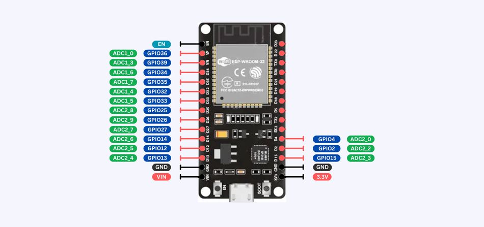
Technical Details:
Calibration: ADC pins require calibration to ensure accurate readings. Calibration involves adjusting the ADC readings to account for any offset and gain errors introduced by the hardware.
Resolution: The ESP32's ADCs typically offer a resolution of 12 bits, which translates to 4096 discrete levels of input signal. [3]
Sampling Rates: The sampling rate of an ADC determines how frequently it can read an analog signal. The ESP32's ADCs support adjustable sampling rates, allowing engineers to balance between accuracy and speed depending on the application's requirements.
Challenges in Practical Implementation:
Noise and Interference: ADC readings can be affected by electrical noise and interference, particularly in environments with many electronic devices. Shielding and proper grounding are essential to mitigate these issues.
Voltage Range: The input voltage range of the ADC pins is limited, typically between 0V and 3.3V. Using voltage dividers or level shifters may be necessary when interfacing with signals outside this range.
Digital-to-Analog Converter (DAC) Pins
DAC pins perform the reverse operation of ADCs, converting digital signals into analog outputs. This functionality is essential for applications such as audio signal generation, analog control signal output, and waveform generation.
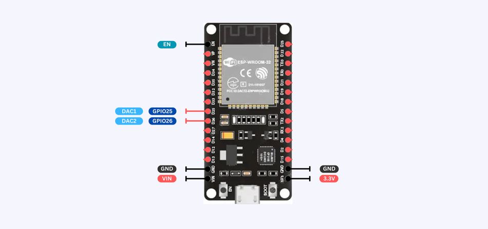
Technical Details:
Resolution: The ESP32's DACs typically offer an 8-bit resolution, resulting in 256 discrete output levels.
Output Range: The output voltage range of the DAC pins generally spans from 0V to 3.3V.
Sampling Rates: Similar to ADCs, DACs have adjustable sampling rates, which can be tuned to meet the needs of various applications, especially those requiring smooth analog outputs.
Challenges in Practical Implementation:
Linear Output: Ensuring a linear analog output can be challenging due to the inherent non-linearities in digital-to-analog conversion. Careful calibration and compensation techniques are often required.
Load Impedance: The load connected to a DAC pin can affect its performance. High-impedance loads are preferred to maintain the accuracy of the output signal.
Other Specialized Pins
In addition to ADC and DAC pins, the ESP32 includes other specialized pins that enhance its functionality:
Touch Sensor Pins: These pins can detect changes in capacitance, enabling touch-sensitive interfaces. These capacitive touch pins can also be used to wake up the ESP32 from deep sleep.
PWM Pins: Pulse Width Modulation (PWM) pins are used to generate analog-like signals from digital outputs, useful in motor control and LED dimming.
Hall Effect Sensor: The ESP32 includes built-in Hall effect sensors that can detect magnetic fields, useful in proximity sensing applications.
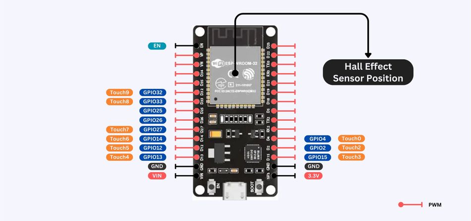
Understanding and effectively utilizing these specialized pins can significantly enhance the performance and capabilities of ESP32-based projects. Engineers can leverage these pins to create sophisticated and responsive systems, making the ESP32 a versatile choice for a wide range of applications.
Enhanced Peripheral Interfaces
The ESP32 microcontroller series has seen substantial improvements in its peripheral interfaces, which are critical for communication and interfacing with various components and devices. These enhancements have significantly impacted the performance and usability of the ESP32, making it a more versatile and powerful tool for engineers.
UART Improvements
The Universal Asynchronous Receiver/Transmitter (UART) interface in the ESP32 has been optimized to provide more reliable and faster serial communication. The enhancements include better hardware flow control, which helps in managing data transmission more efficiently, reducing the chances of data loss or corruption during high-speed communication. This is particularly beneficial in applications requiring robust and stable data exchange, such as industrial automation and robotics.
SPI Enhancements
The Serial Peripheral Interface (SPI) has also been significantly upgraded in the latest ESP32 models. The improvements include higher data transfer rates, which can now reach up to 80 MHz. [4] This increase in speed is crucial for applications that require rapid data acquisition and processing, such as real-time sensors and high-speed data logging systems. Additionally, the SPI interface now supports more advanced configurations, allowing for more complex and flexible peripheral setups.
I2C Advancements
The Inter-Integrated Circuit (I2C) interface has been enhanced to support multiple I2C buses, which greatly increases the flexibility of device connections. This is particularly useful in scenarios where multiple sensors and peripherals need to be connected to a single microcontroller. The improved I2C interface can handle more devices simultaneously without compromising communication speed and reliability. This makes the ESP32 an excellent choice for complex IoT applications and sensor networks.
These enhancements in these peripheral interfaces not only improve performance but also expand the range of possible applications. Engineers can leverage these improvements to design more efficient, and reliable systems, further solidifying the position of ESP32 as a leading microcontroller in the industry.
Suggested Readings: UART vs I2C (vs SPI): Understanding the Differences
Power Management and Efficiency
The ESP32 microcontroller has made significant strides in power management, incorporating features that make it exceptionally energy-efficient. These advancements are particularly important for battery-operated and portable devices, where power consumption is a critical factor.
Advancements in Power Management Features
Recent versions of the ESP32 boards have introduced several power management enhancements. These include the ability to switch between different power modes, each optimized for specific use cases. The power modes range from active mode, where the microcontroller is fully operational, to deep sleep mode, which minimizes power consumption by shutting down most of the internal components while retaining essential functions.
One of the key advancements is the ultra-low-power coprocessor, which can handle simple tasks while the main processors are in deep sleep mode. This feature allows the ESP32 to perform background operations such as sensor monitoring and wake-up trigger detection with minimal energy usage.
Low-Power Modes and Efficient Power Usage
Low-power modes are crucial for extending the battery life of devices, making them ideal for applications where changing or charging batteries frequently is impractical. Efficient power usage not only conserves energy but also reduces heat generation, which can improve the reliability and longevity of the device.
The ESP32 boasts multiple sleep modes, each with varying levels of power consumption and responsiveness:
Active mode: Highest power consumption, suitable for normal operation.
Modem-sleep: Wi-Fi/Bluetooth turned off, consumes less power while maintaining connectivity.
Light sleep: Most peripherals off, ideal for short wake-up intervals.
Deep sleep: Main processor off, minimal power usage, suitable for longer sleep periods with external wake-up triggers.
Hibernation: Deepest sleep mode, lowest power consumption, offers limited functionality upon wake-up.
Strategically transitioning between these modes based on your application's requirements is critical for power efficiency.
Benefits of Efficient Power Management:
Extended Battery Life: By leveraging power modes and managing peripherals, you can significantly extend the battery life of your ESP32-based projects, making them ideal for battery-powered applications.
Reduced Heat Generation: Lower power consumption translates to less heat generation, improving the reliability and lifespan of your ESP32 device.
Cost-Effective Operation: Efficient power usage can lead to lower operating costs for battery-powered devices or those powered by alternative energy sources like solar panels.
By utilizing its low-power modes effectively, engineers can develop solutions that are both powerful and sustainable, meeting the demands of modern applications.
Real-World Applications of ESP32 Pinouts in Engineering
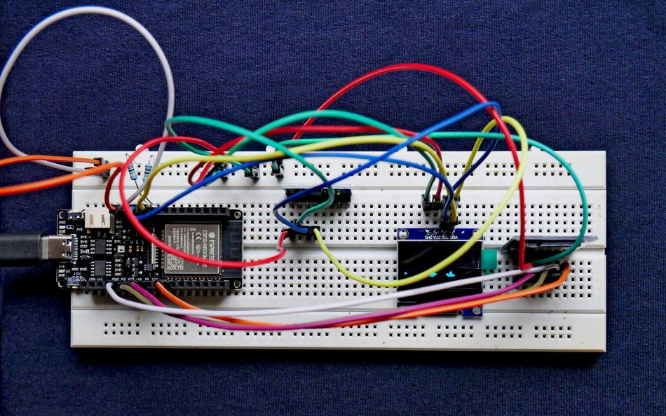
The versatility of ESP32 pinouts has led to their adoption in a wide array of engineering projects, from simple IoT devices to sophisticated robotic systems. Engineers leverage the extensive functionality of ESP32 pinouts to create innovative solutions across various fields.
IoT Projects and ESP32
The comprehensive pinout configuration of ESP32 makes it an ideal choice for IoT projects, enabling seamless connectivity and efficient control of various sensors and actuators.
Smart Home Systems: ESP32 pinouts are used to connect various smart home devices such as lights, thermostats, and security cameras. The GPIO pins control relays and switches, while ADC pins read data from environmental sensors. For instance, an ESP32-based smart thermostat can monitor temperature and humidity using ADC pins and control the HVAC system via GPIO pins. [5]
Wearable Devices: In wearable technology, ESP32 pinouts connect sensors that track vital signs like heart rate and activity levels. The low-power modes and efficient pin configurations ensure long battery life. A fitness tracker can use ADC pins to read signals from bio-sensors and transmit data to a mobile app via UART or Bluetooth pins.
Environmental Monitoring Systems: ESP32 pinouts enable the connection of multiple sensors for monitoring air quality, temperature, and humidity. These systems use ADC pins for analog sensors and I2C or SPI pins for digital sensors. A typical project might involve an ESP32 collecting data from various environmental sensors and sending the information to a cloud server for analysis.
Robotics and Automation
In robotics and automation, the ESP32’s pin configurations facilitate the integration of sensors, motors, and communication modules, allowing for the creation of responsive and intelligent systems.
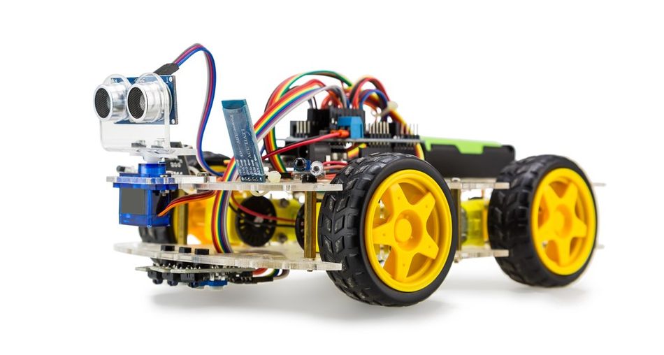
Robotic Arm: An ESP32 can control a robotic arm by using PWM pins to drive servo motors. The ADC pins can read feedback from potentiometers to determine the arm's position, while UART pins communicate with a central controller. This setup allows for precise control and feedback, enabling complex movements and tasks.
Automated Guided Vehicles (AGVs): AGVs use ESP32 pinouts to interface with various sensors and actuators for navigation and obstacle avoidance. GPIO pins connect to motor drivers, ADC pins read data from distance sensors, and SPI or I2C pins handle communication with guidance systems. This configuration ensures the AGVs can operate autonomously in dynamic environments.
Industrial Automation Systems: ESP32 pinouts are utilized in industrial automation for controlling machinery and monitoring processes. GPIO pins are interfaced with relays and switches, while ADC pins gather data from process sensors, and UART or Ethernet pins enable communication with control systems. An example project could involve an ESP32 monitoring temperature and pressure in a manufacturing process and adjusting parameters in real time to maintain optimal conditions.
Detailed Project Descriptions
Smart Irrigation System: This project uses ESP32 pinouts to control water valves and read soil moisture sensors. GPIO pins operate the valves, ADC pins measure soil moisture levels, and Wi-Fi pins connect to a cloud server for data logging and remote control. The system ensures efficient water usage by automatically adjusting irrigation schedules based on real-time soil moisture data.
Home Security System: An ESP32-based home security system uses GPIO pins to interface with motion detectors and door sensors. ADC pins read signals from analog sensors like gas detectors, and the system can send alerts via Wi-Fi or GSM using UART pins. The ESP32’s low-power modes are crucial for battery-operated sensors, ensuring long-term operation without frequent recharging.
These examples demonstrate the vast potential of ESP32 pinouts in creating innovative and efficient engineering solutions. By leveraging the capabilities of these pin configurations, engineers can design robust systems that meet the demands of modern applications. While ESP32 development board can be programmed using the Arduino IDE, it's a different microcontroller with more features.
Recommended Reading: Microcontroller-Based IoT Development Kits: Powering the Next Generation of IoT Solutions
Recent Technological Advancements in ESP32 Pinout
The ESP32 pinout has seen a period of relative stability, focusing on refinement and improved integration with the core functionalities of the microcontroller. However, there are some noteworthy advancements to consider:
Improved Pin Configurations
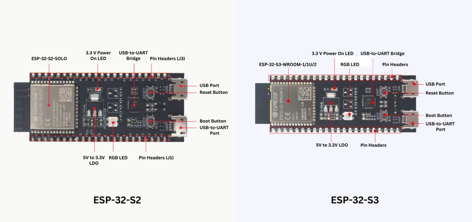
The latest iterations of the ESP32, such as the ESP32-S2 and ESP32-S3, feature refined pin configurations that offer greater flexibility and functionality. These models include additional GPIO pins, which provide more options for interfacing with external components. This allows for more efficient use of available pins, enabling complex projects without sacrificing functionality. Imagine using a single pin for SPI communication or ADC input depending on your project needs.
Enhanced Peripheral Interfaces
The peripheral interfaces in the new ESP32 models have seen substantial upgrades. The SPI interface, for instance, now supports higher data transfer rates, making it more suitable for applications requiring rapid communication, such as real-time data acquisition systems and high-speed sensors. Similarly, the I2C interface has been enhanced to support multiple I2C buses, which allows for more complex multi-device configurations without compromising speed or reliability.
New Pin Functions and Capabilities
New pin functions and capabilities in the latest ESP32 models have broadened their application potential. The ESP32-S2, for instance, includes a USB OTG (On-The-Go) interface, enabling the microcontroller to act as both a USB host and device. This capability expands connectivity options, allowing for direct interfacing with USB peripherals, which is invaluable in applications ranging from data logging to external device control.
Specific Performance Metrics
Performance metrics have also seen substantial improvements. The ESP32-S3, featuring a dual-core Xtensa LX7 processor running at up to 240 MHz, provides a significant boost in computational power compared to earlier models. [6] This increase in processing speed, coupled with enhanced RAM and flash storage capacities, supports more complex and memory-intensive applications. For example, the ESP32-S3 can handle more complex algorithms and larger datasets, making it suitable for advanced automation and IoT applications.
Similarly, ESP32-S3 supports an external 32.768 kHz crystal or an external signal (e.g., an oscillator) to act as the RTC sleep clock. The external RTC clock source is used to improve the timing accuracy and thus reduce the average power consumption, but will not affect the functionality.
It's important to note that these advancements may not be universally available across all ESP32 models. When selecting an ESP32 for your project, consult the specific datasheet, or watch tutorials to understand the latest pinout features and functionalities offered by that particular variant.
While major architectural changes to the ESP32 pinout might be less frequent, the focus remains on improving integration, security, communication capabilities, and power efficiency – all aspects that impact how you leverage the capabilities of ESP32 in your projects.
Challenges and Considerations with ESP32 Pinouts
Engineers working with ESP32 pinouts often encounter several challenges, particularly in complex projects requiring the integration of multiple peripherals. Understanding these challenges and implementing effective solutions is critical to ensure reliable and efficient system performance.
Common Challenges
The ESP32 microcontroller, known for its versatility and rich feature set, also brings certain complexities. One primary challenge is pin conflicts, which occur because many pins serve multiple functions. This multiplexing capability, while powerful, can lead to conflicts when multiple functions compete for the same pin. Let’s say, a pin designated for GPIO might also be needed for an ADC function in the same project, necessitating careful planning and configuration.
Another significant challenge is maintaining signal integrity. Ensuring clean, interference-free signals is crucial, especially in high-speed or high-frequency applications. Noise and electromagnetic interference can degrade signal quality, leading to errors and unreliable operation.
Power management is also a critical consideration, particularly in battery-operated devices where efficiency is paramount. Balancing power consumption with performance requires a deep understanding of the power modes and capabilities of ESP32.
Lastly, thermal management is essential to prevent overheating. As the ESP32 handles various intensive tasks, it can generate significant heat. Without proper thermal management, this can lead to thermal throttling or even damage to the microcontroller.
Mitigation Strategies
To address pin conflicts, engineers should engage in careful pin mapping. This involves planning the use of each pin from the project's outset, taking advantage of the GPIO matrix of ESP32 to reassign functions dynamically as needed. This strategy helps in resolving conflicts by reallocating functions to less critical pins.
For maintaining signal integrity, proper grounding and shielding techniques are vital. Ensuring that all components share a common ground (GND) and using shields to protect sensitive signals from interference can significantly reduce noise. Additionally, keeping signal paths as short as possible minimizes potential interference.
Effective power management can be achieved by utilizing the low-power modes of ESP32. These modes allow the microcontroller to enter a state of reduced power consumption while maintaining essential operations. For instance, in wearable technology, where battery life is crucial, employing deep sleep modes can extend operational time without frequent recharging.
Thermal management can be addressed by incorporating design elements such as heatsinks, adequate ventilation, or even active cooling solutions in more demanding applications. Monitoring temperature with onboard sensors and adjusting performance dynamically based on thermal conditions can also help maintain optimal operating temperatures.
Practical Tips and Best Practices
Using dedicated pins for critical functions where possible helps to avoid conflicts and ensure reliable operation. Regularly calibrating ADC and DAC pins maintains accuracy in analog signal processing, which is crucial for applications requiring precise measurements.
Keeping the firmware updated is essential to benefit from the latest improvements and bug fixes related to pin functionality and performance. Additionally, designing systems in a modular fashion allows for easier upgrades and maintenance without significant redesigns.
Advanced Troubleshooting Techniques
Pin diagnostics tools can monitor the state of each pin, helping to identify conflicts or issues. Utilizing oscilloscopes or logic analyzers for signal analysis ensures signal integrity and detects interference. For thermal management, thermal imaging cameras can identify hotspots, verifying the effectiveness of cooling solutions.
By understanding these challenges and adopting best practices, you can effectively navigate the complexities of the ESP32 pin out. This empowers you to design robust and reliable embedded systems that leverage the full potential of this powerful microcontroller.
Overcoming Pin Conflicts
Pin conflicts can complicate ESP32 projects, but with strategic planning and management, they can be effectively mitigated.
Common Pin Conflict Scenarios
GPIO vs. Analog Functions: A single pin might be required for both digital I/O and analog functions like ADC or DAC, leading to conflicts.
Multiple Peripherals on the Same Bus: I2C and SPI peripherals often share pins, which can cause conflicts if not managed properly.
Strategies for Managing Pin Conflicts
The GPIO matrix of ESP32 allows for the dynamic reassignment of functions to different pins, helping to resolve conflicts. Using dedicated buses for different peripherals can prevent conflicts by isolating their communication channels.
Common Solutions
Use Alternative Pins: Identifying and using alternative pins that can serve the same function without conflict is a practical approach.
Firmware Adjustments: Adjusting firmware settings to dynamically change pin assignments based on current operational needs can help manage conflicts effectively.
External Multiplexers: Employing external multiplexers can expand the number of available pins, offering more flexibility in pin assignments.
Ensuring Reliable Connections
Ensuring reliable connections is crucial for maintaining signal integrity and overall system stability in ESP32 projects.
Importance of Reliable Connections
Reliable connections are vital for the accurate transmission of signals without degradation or interference. This is especially critical in applications where data integrity and timing are crucial, such as in industrial automation and real-time data acquisition.
Tips for Maintaining Signal Integrity
Proper Grounding: Ensure all components have a common ground to reduce noise and interference.
Short Signal Paths: Keeping signal paths as short as possible minimizes potential interference and signal degradation.
Twisted Pair Cables: Using twisted pair cables for differential signals reduces electromagnetic interference.
Avoiding Interference
Shielding: Shielding sensitive signal lines can protect against external noise.
Decoupling Capacitors: Placing decoupling capacitors near the power supply pins of the ESP32 helps filter out noise.
Isolated Power Supplies: Using isolated power supplies for different sections of the circuit prevents noise from propagating.
Recommendations for Connection Reliability
| Recommendation | Description |
| Proper Grounding | Ensure all components share a common ground to reduce noise. |
| Shielding | Shield signal lines to protect against electromagnetic interference. |
| Twisted Pair Cables | Use twisted pairs for differential signals to minimize noise. |
| Decoupling Capacitors | Place near power supply pins to filter noise. |
| Short Signal Paths | Keep connections short to avoid signal degradation. |
Implementing these tips and best practices can significantly enhance the reliability of connections in ESP32 projects, ensuring stable and robust performance.
Conclusion
Throughout this article, we have explored the intricate details of the ESP32 pinout architecture, emphasizing its relevance and application in modern engineering projects. We discussed foundational concepts such as GPIO, ADC, and DAC pins, delved into recent technological advancements, and highlighted practical applications in fields like IoT and robotics. Understanding and utilizing ESP32 pinouts effectively is crucial for optimizing performance and achieving innovative engineering solutions. We encourage engineers to experiment with different pin configurations, leveraging the flexibility and power of the ESP32 to enhance their projects and push the boundaries of what is possible.
Frequently Asked Questions (FAQs)
Q. What is the purpose of GPIO pins on the ESP32?
A. GPIO (General Purpose Input/Output) pins on the ESP32 are versatile and can be configured as either input or output. They are used for a wide range of tasks such as reading sensor data, controlling LEDs, and interfacing with other digital devices.
Q. How do I use the ADC pins on the ESP32?
A. To use the ADC (Analog-to-Digital Converter) pins on the ESP32, you need to configure the pin as an ADC input in your code. Flash memory stores the ESP32 program code. The ESP32 ADCs convert the analog voltage signal into a digital value that can be processed by the microcontroller. Typical uses include reading analog sensors like temperature or light sensors.
Q. What are the common challenges when working with ESP32 pinouts?
A. Common challenges include managing pin conflicts, ensuring signal integrity, and handling power management efficiently. Pin conflicts arise when multiple functions need the same pin. Signal integrity issues can be caused by noise and interference, while power management is crucial for battery-operated devices.
Q. How can I ensure reliable connections with ESP32 pinouts?
A. To ensure reliable connections with ESP32 pinouts, use proper grounding techniques, keep signal paths short, and use twisted pair cables for differential signals. Additionally, shielding sensitive signal lines and placing decoupling capacitors near power supply pins can help maintain signal integrity and reduce noise.
References
[1] Espressif. ESP32 DevKit Datasheet [Cited 2024 June 30] Available at: Link
[2] Espressif-docs. GPIO Matrix and Pin Mux [Cited 2024 June 30] Available at: Link
[3] Norvi. Why should use ESP32-based PLC with Analog Inputs [Cited 2024 June 30] Available at: Link
[4] Wevolver. SPI Protocol: Revolutionizing Data Communication in Embedded Systems [Cited 2024 June 30] Available at: Link
[5] Randomnerdtutorials. ESP32/ESP8266 Thermostat Web Server – Control Output Based on Temperature [Cited 2024 June 30] Available at: Link
[6] Espressif. ESP32-S3 Wi-Fi & BLE 5 SoC [Cited 2024 June 30] Available at: Link
in this article
1. Introduction2. Understanding the ESP32 Pinout Architecture3. Specialized Pins: ADC, DAC, and More4. Enhanced Peripheral Interfaces5. Power Management and Efficiency6. Real-World Applications of ESP32 Pinouts in Engineering7. Recent Technological Advancements in ESP32 Pinout8. Challenges and Considerations with ESP32 Pinouts9. Overcoming Pin Conflicts10. Ensuring Reliable Connections11. Conclusion12. Frequently Asked Questions (FAQs)13. References