What Is a Shunt Resistor? Sizing, Sensing, and Layout
A shunt resistor turns a current you cannot measure directly into a small voltage you can. This guide covers how shunt resistors work, how to size one, why manganin dominates precision designs, and where real measurement errors come from.

04 Sep, 2026. 13 minutes read
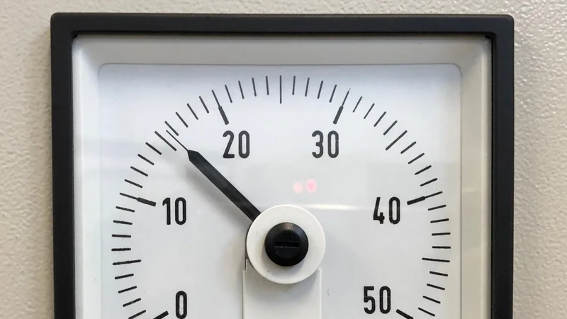
Shunt resistors are pivotal elements in current measurement devices
Key Takeaways
A shunt resistor is a low-value precision resistor placed in series with a load so the voltage drop across it is proportional to current, by Ohm's law. Conventional full-scale drops are 50 mV, 75 mV, or 100 mV.[1]
Power dissipation, not resistance, usually sets the part choice. A 1 mΩ shunt carrying 50 A dissipates 2.5 W, and derating rules push you to a 5 W to 8 W part.[1]
The dominant error in a low-value shunt is thermal drift, not initial tolerance. A 1 mΩ Vishay WSL2512 has an element TCR below 20 ppm/°C but a component TCR of ±275 ppm/°C, because the copper terminals sit inside the measured path.[2]
Four-terminal (Kelvin) sensing recovers accuracy. Sensing from the wrong point in a parallel shunt array produces an error, so it’s important to sense from a symmetrical point.[3]
Parasitic inductance sets the usable bandwidth at f = R / (2πL). A 1 mΩ shunt with 2 nH of inductance rolls off below 80 kHz, which matters in any PWM motor drive.
Introduction
Electric current cannot be sensed directly. It must be converted into something measurable. There are two practical methods to solve this problem:
Measure the magnetic field around the current-carrying conductor
Measure the voltage across a known resistance.[4]
The second method uses a shunt resistor, and it is more common because it is accurate, linear, and cheap.
The idea is older than electronics itself. Electrical shunts let a moving-coil ammeter with a 50 mV full-scale deflection read hundreds of amps by diverting almost all of the electric current around the meter movement.[5]
Even in modern electronics, the physics behind shunt resistance remains the same. However, modern systems require higher precision. For instance, a modern battery monitor in an electric vehicle needs to integrate charge over years without drifting. Likewise, a motor drive needs to sample current inside a 20 kHz PWM cycle.
This article discusses the engineering behind shunt resistance and how it helps in designing trustworthy current measurement systems.
How a Shunt Resistor Works
A shunt resistor is connected in series with the load. All of the load current flows through it, and the differential voltage it develops is measured across it.
So, the governing relationship is simply Ohm's law:
Vshunt = I × Rshunt
Rearranged for design, the resistance can be calculated as:
Rshunt = Vshunt(max) / I(max)
Vshunt(max) is the single most critical parameter. It refers to the full-scale voltage drop.
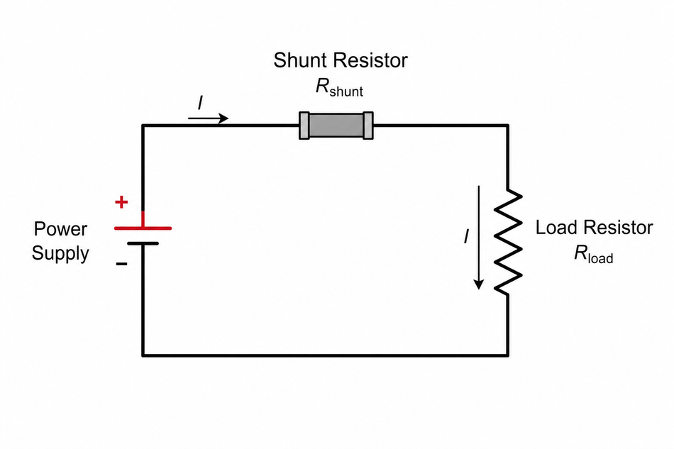
A larger drop gives a bigger signal and better noise immunity, but it wastes more power and steals voltage headroom from the load. On the other hand, a smaller drop is more efficient but pushes the signal down toward the offset voltage and noise floor of whatever amplifier reads it.
The following table shows the resistance and dissipation that result from two conventional full-scale drops:
Full-scale current | Rshunt at 50 mV | Dissipation at 50 mV | Rshunt at 100 mV | Dissipation at 100 mV |
1 A | 50 mΩ | 0.05 W | 100 mΩ | 0.1 W |
10 A | 5 mΩ | 0.5 W | 10 mΩ | 1 W |
50 A | 1 mΩ | 2.5 W | 2 mΩ | 5 W |
100 A | 500 µΩ | 5 W | 1 mΩ | 10 W |
200 A | 250 µΩ | 10 W | 500 µΩ | 20 W |
500 A | 100 µΩ | 25 W | 200 µΩ | 50 W |
There are two important things to note:
High-current shunts operate in the milliohm and microohm range, so parasitic resistances that are normally invisible become first-order error terms.
Power dissipation increases rapidly as current increases. Typically, SMD components fail at 10W and above.
Four-Terminal (Kelvin) Sensing
Because shunt resistances are so low, the resistance of the solder joints and the copper approaching the part is comparable to the shunt itself. Texas Instruments measured the solder between a shunt and its resistor pad at roughly 10 µΩ to 100 µΩ, and 1 oz copper contributes about 500 µΩ per square.[3] Therefore, a 100 µΩ shunt can have as much unwanted resistance around it as inside it.
To bypass this problem, a four-terminal, or Kelvin, connection is needed. Two heavy terminals carry the load current, and two separate high-impedance terminals pick off the voltage from inside the current path. As a result, the sense loop never includes the solder joints or approach traces.
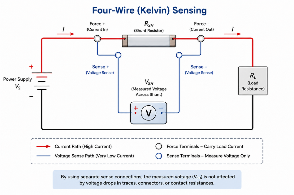
In modern electronics, Kelvin sensing is standard practice for values below 0.5 mΩ, and Texas Instruments recommends four-terminal parts wherever the highest accuracy is required, with the caveat that misinstallation can route primary current through the sense connections and damage the amplifier.[1]
Design engineers who prefer a two-terminal current sense resistor must connect the sense traces at the inner edge of each landing pad. Most of the current has already left the copper by that point, so the inner half of the pad is effectively a high-impedance node and behaves like a Kelvin tap.[6]
Suggested Reading: Current-Limiting Resistor: Theory, Design and Practical Applications for Engineers
Shunt Resistor Types and Materials
Construction determines resistance range, power handling, drift, and cost. Texas Instruments summarizes the practical options as follows [1]:
Technology | Metal element (SMD) | Metal foil (SMD) | Metal element (chassis) | Wire-wound |
Resistance range | 0.1 mΩ to 1 Ω | 0.5 mΩ to 0.7 Ω | 25 µΩ to 0.1 Ω | above 5 mΩ |
Power range | 1/16 W to 20 W | 1/80 W to 10 W | 0.25 W to 100 W | 0.5 W to 1 kW |
Tolerance | 0.1% to 5% | 0.01% to 10% | 0.1% to 1% | 0.1% to 10% |
Drift | 15 to 750 ppm/°C | 0.2 to 1000 ppm/°C | 20 to 100 ppm/°C | 20 to 400 ppm/°C |
Pulse capability | up to 275 °C | up to 225 °C | up to 175 °C | 275 °C and above |
Relative cost | low | medium | high | high to low |
Surface-mount metal element parts are the default for most designs because they are low resistance, high power in a small footprint, and low cost.
Metal foil offers better initial accuracy, but is more expensive.
Chassis-mount parts are considerably high-power, operating above 20 W, where heat must leave through the conductor rather than the board.
Suggested Reading: What Is a Resistor in a Circuit? Theory, Types, and Practical Applications
Why Manganin Dominates Precision Shunts
The resistance alloy inside a precision resistor is almost always manganin or a close relative. Isabellenhütte's MANGANIN is CuMn12Ni, i.e., copper with 12% manganese and 2% nickel. Its published properties explain the choice [7]:
Resistivity of 43 µΩ·cm, high enough to make a usable resistor out of a short, low-inductance piece of metal.
Temperature coefficient of ±10 ppm/K between +20 °C and +50 °C. The resistance versus temperature curve is parabolic near room temperature, so a TCR figure is only meaningful if the temperature range is quoted with it.
Thermal EMF against copper is just -1.0 µV/K, which limits the parasitic thermocouple voltage generated wherever the alloy meets the copper terminals.
Density is 8.40 g/cm³, and the maximum working temperature in air is +140 °C.
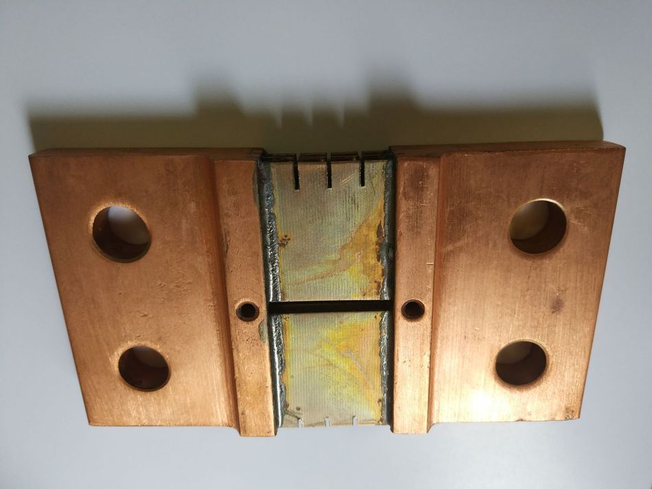
Above +140 °C, manganin oxidizes, and the resistance drifts permanently. A study of 100 µΩ Cu86Mn12Ni2 shunts found that 168 hours at 200 °C raised resistance by 1.85% in untrimmed parts and 2.29% in trimmed parts, with oxygen content in the surface rising from roughly 3.4% to 5.5% by weight, up to 11.9% to 14.7%.[8]
Wikipedia's summary of manganin shunt behavior is consistent: drift begins around 80 °C, becomes significant at 120 °C, and permanent annealing damage occurs near 140 °C.[5]
The same study is a useful reminder that the alloy is not the whole story. Measured TCR was +106 ppm/°C untrimmed and +93 ppm/°C trimmed, far above the ±15 ppm/°C of pure manganin, because the copper terminations contribute a strongly positive TCR in series with the element.
Sizing a Shunt Resistor
The following example illustrates the sizing of a shunt resistor. Take a 48 V motor drive that has to measure bidirectional current up to ±50 A, with 100 A fault transients.
Step 1 - Pick the full-scale shunt voltage
Choose 50 mV, the conventional value. It is large enough to sit well above the amplifier offset and small enough that the dissipation stays manageable.
Step 2 - Calculate the resistance
Shunt resistance can be derived using Ohm’s law as:
Rshunt = 50 mV / 50 A = 1 mΩ
Step 3 - Calculate power dissipation
P = I² × R = (50 A)² × 0.001 Ω = 2.5 W
Step 4 - Derate Shunt Resistance
This is where most designs go wrong. Two independent rules converge on the same answer:
Renesas advises multiplying the calculated dissipation by two, so the part survives currents above the measurable maximum, giving 5 W.[6]
Texas Instruments states that a shunt cannot run continuously beyond two-thirds of its rated current even with good heat sinking, which for 50 A implies a part rated for 75 A, or 75² × 0.001 = 5.6 W.
Specify a 5 W (2512) or 8 W (3920) metal element part. Around 90% of the heat from a surface-mount shunt leaves through the PCB trace, so copper area becomes a critical design variable.
Step 5 - Check the fault Case
At 100 A, the shunt dissipates 10 W. This can be verified against a short-term overload rating in the datasheet, and confirm the 100 mV drop does not violate the amplifier's absolute maximum input.
Overvoltage at the amplifier inputs during a short circuit is a classic failure. TI's isolated data converter inputs, for example, typically withstand -6 V to the high-side supply plus 500 mV.
Step 6 - Check Self-heating.
Using the Renesas relationship ΔT = θ_ja × I²R, a 2512 package with a thermal resistance of 25 °C/W dissipating 2.5 W rises about 62 °C above ambient. Hold that number: it drives the error budget.
Recommended Reading: Accurate Measurements using Shunt Resistors and Current Sense Modules in High-Energy Storage Applications
Building the Error Budget
Pair the 1 mΩ shunt with a Texas Instruments INA240A1 current sense amplifier (gain 20 V/V), which turns 50 mV of shunt voltage into 1.0 V of output. On a 5 V supply with the reference at mid-rail, that leaves comfortable headroom for bidirectional measurement.
Now account for every error term. The following table summarizes the Shunt figures[2] and amplifier figures[9].
Error source | Specification | Contribution at full scale |
Shunt initial tolerance | ±1.0% (F grade) | 1.00% |
Shunt component TCR over 62 °C rise | ±275 ppm/°C at 1 mΩ | 1.71% |
Amplifier gain error | ±0.20% max | 0.20% |
Amplifier offset voltage | ±25 µV max on 50 mV | 0.05% |
Amplifier CMRR at 48 V common mode voltage | 120 dB min (1 µV/V) | 0.10% |
Worst-case total | 3.06% |
The result is instructive. The amplifier contributes about 0.35%. The shunt contributes about 2.7%, and most of that is thermal drift.
The fix is in the same datasheet. Vishay quotes the element TCR of the WSL alloy at below 20 ppm/°C, against a component TCR of ±275 ppm/°C at 1 mΩ. The difference is the copper terminals, which sit inside the measured path in a two-terminal part.[2]
Over the same 62 °C rise, an element TCR of 20 ppm/°C contributes only 0.12%. That is the concrete argument for four terminals: it can remove more than a percentage point of error from this design.
High-Side vs Low-Side Current Sensing
Where you put the shunt is a system decision. Low-side means between the load and ground; high-side means between the supply and the load. The following table summarizes[4]:
Criterion | High-side sensing | Low-side sensing |
Input configuration | Differential | Single-ended or differential |
Ground disturbance | No | Yes |
Common mode voltage | Close to supply | Close to ground |
CMRR requirement | Higher | Lower |
Detects load short circuit | Yes | No |
Relative cost | Higher | Lower |
Low-side sensing is cheaper because the common-mode voltage is close to ground, so an ordinary low-voltage amplifier will be sufficient. The costs are that the shunt inserts resistance into the ground return, lifting the load's ground reference, and that a short from the load to ground bypasses the shunt entirely and goes undetected.
High-side sensing keeps the ground path clean and catches load shorts, but the amplifier has to reject a common-mode voltage set by the supply rail. In a 48 V system, that means a part rated well above 48 V.
Automotive and battery applications increasingly favor high-side placement precisely for fault detection, even though it requires a differential measurement.[10]
PCB Layout for Shunt Resistance
PCB layout is not a finishing step for a milliohm-scale measurement. It is part of the measurement.
Texas Instruments simulated three layouts for three shunts in parallel (270 µΩ, 300 µΩ, and 330 µΩ, a deliberate 10% spread) carrying 20 A into an INA190 at a gain of 200 V/V. The calculated output for the 99.33 µΩ effective resistance is 397.32 mV. The results are [3]:
Kelvin sensing from the shunt nearest the amplifier: 56.47 mV of offset, a 14.2% error. The sense traces tap the current path far from the other shunts, so solder and trace drops end up inside the differential measurement.
Kelvin sensing from the middle shunt: 51.22 mV of offset. Better, but the copper layer still offers parallel paths, so only 5.77 A of the 20 A actually flows through the sensed part.
Individual Kelvin connections from every shunt: closest to the calculated value, and accurate regardless of how the current divides.
Practical rules that follow from this work and from the Renesas layout guidance:
Make the traces to parallel shunts identical in length and width. Uneven resistance means uneven current sharing, and the hotter resistor drifts further, which worsens the imbalance.
Put current-limiting resistors at least 100 times the shunt value in series with each Kelvin trace. Multiple Kelvin taps form low-impedance loops, and without limiting resistors, hundreds of milliamps circulate and generate heat.
Route the two sense traces closely together so the magnetic fields cancel outside the pair, and keep them away from high-current conductors.
Use arcs or 45-degree bends on high-current traces. Orthogonal corners cause current crowding and localized heating.
Verify the reflow profile with your manufacturer. Bad soldering shows up as high initial error, uneven heat dissipation, or an open circuit.
Suggested Reading: Next-Generation Current Measurement: Addressing PCB Design Challenges with Magnetic Current Sensors
Bandwidth and Parasitic Inductance
A shunt resistor is a resistor in series with a parasitic inductance. That inductance sets a corner frequency:
fc = Rshunt / (2π × Lshunt)
Above fc, the inductive impedance dominates, and the nominal resistance stops mattering. The equation is unforgiving at low resistance. Vishay specifies 0.5 nH to 5 nH for the WSL family; a 1 mΩ part with 2 nH of inductance corners at just 80 kHz, which is inside the switching band of a typical motor drive and will exaggerate every edge.[2]
Tektronix measured the corner frequency for parasitic inductance directly. A 50 mΩ thin-film resistor in an 0612 package showed a corner frequency of 15.1 MHz on a vector network analyzer, corresponding to about 530 pH of effective series inductance. In the time domain, the step response showed extreme overshoot compared with a 1 GHz passive probe.[11]
There are three practical mitigations to overcome parasitic inductance:
As bandwidth rises linearly with R, it is best to start with the largest resistance the design can tolerate.
Choose wide, short packages such as 0612, and prefer thin film or metal foil over wire-wound.
Compensate with an RC network with a pole matching the shunt's zero flattens the response, using C = Lshunt / (Rshunt × Rtermination)
Putting several shunts in parallel also reduces total inductance. Therefore, parallel arrays appear in high-power designs alongside the thermal argument.
Shunt Resistors vs Hall Effect Sensors and Current Transformers
Criterion | Shunt resistor | Hall effect sensor | Current transformer |
Principle | Ohm's law | Magnetic field density | Faraday induction |
Galvanic isolation | No (needs isolated amplifier) | Yes | Yes |
DC capability | Yes | Yes | No |
Insertion loss | Yes, I²R | Negligible | Negligible |
Magnetic interference | Immune | Susceptible | Susceptible |
Saturation | None | Possible | Yes |
Relative cost | Low | Higher | Higher |
A shunt is the most accurate, most linear, and cheapest option, with the best long-term stability and low offset drift, and it is immune to magnetic interference.[1] But it comes at a cost of isolation and efficiency, since it always consumes power and eats voltage headroom.
When you need isolation with shunt accuracy, the standard answer is a shunt paired with an isolated amplifier. Otherwise, an isolated ADC across a capacitive isolation barrier can be used. In fact, it is now common in electric vehicle powertrains, charging infrastructure, and high-voltage battery monitors.
A third option worth knowing is DCR sensing, which measures the voltage across the parasitic resistance of an existing inductor and is therefore lossless. It suits regulated rails below about 1.5 V where a shunt's drop would be a large fraction of the supply.
Recommended Reading: Hall Effect Current Sensor: Principles, Topologies and Engineering Applications
Shunt Resistor Applications
Battery monitors and BMS. Shunts integrate charge and discharge current to estimate state of charge, where long-term stability matters more than absolute accuracy at a single point.
Motor drives. Phase current feedback inside the control loop, where bandwidth and PWM rejection dominate.
Power supplies and e-fuses. Overcurrent and short-circuit protection, current limiting, and monitoring of load current draw.
DC energy metering and test equipment. Precision resistor-grade parts, often four-terminal, with calibration traceable to a reference.
Ammeter range extension. The original use for electrical shunts, still standard in panel meters: a 500 A shunt rated at 75 mV has a resistance of 150 µΩ, and a 66% derating factor means it should not carry more than 330 A continuously.[5]
For low-current work such as leakage current measurement, a benchtop digital multimeter will resolve DC down to the picoampere range using internal current-sense resistors, though typically only below 1 MHz.[10]
Shunt resistors and testing methods for fixed resistors generally are covered by IEC 60115-1:2020, the fifth edition of the generic specification for fixed resistors published on 18 March 2020 by IEC technical committee TC 40.[12] It defines the terms, inspection procedures, and test methods (resistance measurement, temperature coefficient testing, endurance, high-voltage overload, solderability, and climatic sequence) that sectional and detail specifications build on.
Common Mistakes and Troubleshooting
Sensing from the Wrong Point
The single largest avoidable error. If a reading is consistently high and scales with load current, check whether solder joints or approach copper are inside the sense loop.
Ignoring Derating
A part rated at 2.5 W running at 2.5 W will drift and may fail. Measure terminal temperature at maximum nominal operation and check it against the power derating curve.
Treating Shunt as Protection
A shunt is not a fuse. It has no defined interrupting behavior, and a sustained overload can permanently alter its properties or open it unpredictably.
Ignoring Inductance in Switched Circuits
Ringing, exaggerated peaks, and overshoot on a shunt waveform in a PWM system usually indicate the corner frequency is inside the band of interest, not a real current spike.
Conclusion
A shunt resistor is conceptually the simplest way to measure current, and that simplicity hides where the engineering actually lives. The resistance is calculated with Ohm's law once a full-scale voltage drop is finalized. Everything after that (power rating, derating, alloy choice, four-terminal construction, layout, and parasitic inductance) is what separates a measurement that holds 1% over temperature from one that drifts 3%.
Two numbers are worth carrying away. Thermal drift, not initial tolerance, usually dominates the error budget in a low-value shunt, and the copper terminals are usually the reason. And bandwidth is set by R over L, so the lower the resistance, the sooner the measurement stops being resistive.
Frequently Asked Questions
1. What is a shunt resistor used for?
It converts electric current into a proportional voltage that a meter, ADC, or amplifier can read. Typical uses are battery monitoring, motor drive current feedback, power supply protection, energy metering, and extending the range of an ammeter.
2. What is the difference between a shunt resistor and a normal resistor?
Shunt resistors are optimized for very low resistance (microohms to a few hundred milliohms), high current, low temperature coefficient, and low inductance. Standard resistors optimize for value range and cost. Many current sense resistors also add four terminals, which ordinary parts do not have.
3. Why is manganin used for shunt resistors?
Manganin (CuMn12Ni) combines a very low temperature coefficient of about ±10 ppm/K near room temperature, extremely low thermal EMF against copper (-1.0 µV/K), and good long-term stability. Its practical limit is a maximum working temperature of +140 °C in air, above which oxidation causes permanent drift.
4. Can you measure a shunt resistor with a multimeter?
Not usefully in the two-wire resistance mode. At milliohm values, the multimeter's own lead and contact resistance swamps the reading. Use a four-wire (Kelvin) resistance measurement, or measure the voltage drop at a known current and calculate.
5. Do shunt resistors work with alternating current?
Yes, and unlike current transformers, they work down to DC. The limit is bandwidth: parasitic inductance produces a corner frequency at R / (2πL), so high-frequency alternating current measurement needs a low-inductance part, a compensation network, or a coaxial design.
6. What happens if a shunt resistor is undersized?
It self-heats, its resistance climbs with its temperature coefficient, and the current reading drifts. Past the alloy's maximum working temperature, the change becomes permanent. In severe overload, the part can go open circuit, which in a low-side configuration disconnects the load's ground return.
References
Texas Instruments. Shunt Resistor Selection for Isolated Data Converters (SBAA460). May 2023.
Vishay Dale. WSL Power Metal Strip Resistors, Low Value, Surface-Mount (Document 30100). Revised November 2023.
Texas Instruments. Optimal Layout Practices for Low-Ohmic Current Sense Resistors in Parallel (SDAA115). November 2025.
Texas Instruments. System Trade-offs for High- and Low-side Current Measurements (SSZTA51). June 2017.
Wikipedia. Shunt (electrical).
Renesas. Sensing Elements for Current Measurements (White Paper).
Isabellenhütte Heusler. MANGANIN Data Sheet. October 2022.
Bahrami, A. et al. Effect of Abrasive Machining on the Electrical Properties of Cu86Mn12Ni2 Alloy Shunts. Materials, 2017.
Texas Instruments. INA240 High-Precision, Current Sense Amplifier Data Sheet (SBOS662C). Revised December 2021.
Tektronix. Measuring Current using Shunt Resistors.
Tektronix. Compensating for Series Inductance in Shunt Resistors for High Frequency Measurements (White Paper).
International Electrotechnical Commission. IEC 60115-1:2020, Fixed resistors for use in electronic equipment, Part 1: Generic specification. Edition 5.0, 18 March 2020.
in this article
1. Introduction2. How a Shunt Resistor Works3. Shunt Resistor Types and Materials4. Sizing a Shunt Resistor5. High-Side vs Low-Side Current Sensing6. PCB Layout for Shunt Resistance 7. Bandwidth and Parasitic Inductance8. Shunt Resistors vs Hall Effect Sensors and Current Transformers9. Shunt Resistor Applications10. Common Mistakes and Troubleshooting11. Conclusion12. Frequently Asked Questions13. References