Instrumentation Amplifier: Theory, Three-Op-Amp Design, CMRR
An instrumentation amplifier is a precision differential amplifier designed to amplify small voltage differences. This guide explains the three-op-amp architecture, and how to choose between INA128, AD620, LT1167, and a standard difference amplifier for sensor front-ends.

30 Jul, 2026. 13 minutes read
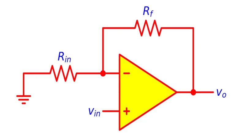
Non-inverting op-amp circuit diagram
Key Takeaways
● Instrumentation amplifiers are precision differential amplifiers with input buffers. They are built from three operational amplifiers, two of which act as high-impedance non-inverting buffers feeding a differential output stage. This configuration gives the in-amp high input impedance, low offset, low drift, and high common-mode rejection ratio (CMRR).
● Gain is set by a single resistor. In the classic three-op-amp instrumentation amplifier, a resistor between the buffer inverting inputs sets the differential-mode gain. The gain expression G = 1 + 2R/Rg multiplies the gain of the output stage, simplifying design and improving CMRR.
● Topologies serve different needs. Difference amplifiers handle large common-mode voltages and are suited to high-side current sensing and battery monitoring, whereas instrumentation amplifiers excel with high-impedance sensors requiring high gain and low noise.
● Modern instrumentation amplifier ICs integrate laser-trimmed resistors for accuracy. Devices like INA128, AD620, LT1167, and newer precision amplifiers provide adjustable gain from 1 to 10,000, high CMRR (90–120 dB), low input noise (<10 nV/√Hz), and operate from supplies as low as ±2.3 V.
● Selecting the right amplifier depends on source impedance, common-mode voltage, and required gain. Use difference amplifiers for low-impedance sources with large common-mode voltages, and instrumentation amplifiers for high-impedance transducers such as strain gauges, thermocouples, and biomedical electrodes.
Introduction
Precision measurement often requires amplifying microvolt differences while rejecting common-mode voltage. Simple difference stages built with a standard operational amplifier perform this function, but resistor mismatches limit CMRR and input impedance. Two topologies address these limitations: the difference amplifier, which uses a single op-amp and four resistors to extract the difference between two signals, and the instrumentation amplifier, which combines input buffers with a difference stage.
A difference amplifier offers simplicity and can handle common-mode voltages far beyond its supply rails. A single resistor network sets the gain, but imperfect matching degrades CMRR and the input impedance is limited to the resistor values. In-amps solve these problems by adding two non-inverting buffers ahead of the difference stage. The buffers provide very high input impedance and isolate the source from the feedback network. A single gain-setting resistor adjusts differential gain without disturbing resistor matching. In-amps are thus ideal for low-level signals from high-impedance sensors such as strain gauges, thermocouples, and biomedical electrodes, whereas difference amplifiers excel in high-side current sensing and battery monitoring. The sections that follow explore these topologies, compare integrated in-amp ICs, and discuss applications and design considerations.
Recommended reading: Operational Amplifier: Theory, Design, and Applications for Engineers
Instrumentation Amplifier Fundamentals
Instrumentation amplifiers are precision differential amplifiers optimized for measurement and sensor interfaces. They combine two buffer stages with a difference stage to achieve very high input impedance and high common-mode rejection. A single resistor sets the gain over a wide range, and increasing the gain improves CMRR. The three op-amps isolate the sensor from the feedback network and feed a differential amplifier. Integrated in-amp ICs include laser-trimmed resistors for accurate matching and are widely used in data acquisition, medical electronics, and industrial sensing.
Three-Op-Amp Instrumentation Amplifier Topology
The three-op-amp design is still the industry default because it delivers high input impedance, easy gain control, and strong CMRR from a well-understood resistor network.
The three-op-amp instrumentation amplifier remains the most common implementation because it offers high input impedance, easy gain control, and excellent CMRR. The topology uses equal resistors R and a gain-setting resistor Rg. Below, we explore each part of the circuit in more detail.
Classic Three-Op-Amp Circuit
The classic in-amp uses two high-impedance non-inverting buffers to drive a differential amplifier. A third op-amp and four resistors form the output stage, with matched resistor pairs R1 = R3 and R2 = R4 to reject common-mode signals. This output stage acts as an inverting difference amplifier. A gain-setting resistor Rg ties the buffer inverting inputs: if Rg is removed, the circuit reduces to a differential amplifier; inserting Rg increases the differential gain while leaving common-mode gain near unity.
Recommended reading: Non-Inverting Amplifier Design: Op-Amp Theory, Bandwidth, Noise, and Practical Implementation
The Gain-Setting Resistor Rg
The gain-setting resistor Rg between the inverting inputs of the two buffer op-amps determines the instrumentation amplifier's differential gain. With equal resistors in the output stage, the gain simplifies to:
G = (1 + 2R/Rg) · (R3/R2)
Because only one resistor needs to be changed, adjusting Rg allows designers to set the gain over a wide range without disturbing resistor matching. Lowering Rg increases differential gain while leaving the common-mode gain near unity, which improves CMRR. When Rg is open-circuited, the first stage gain reduces to unity and the overall gain is set by R3/R2. IC instrumentation amplifiers provide recommended Rg values for common gain settings.
Recommended reading: Inverting vs Non-Inverting Op-Amp: Complete Design Guide & Best Practices
Transfer Function Derivation
Assume both input buffers use equal feedback resistors R and share a gain-setting resistor Rg. Each buffer is wired as a non-inverting amplifier, but the resistor Rg couples their inverting inputs. When a differential voltage V2 − V1 is applied, a current flows through Rg and drops a voltage proportional to the input difference. This voltage is fed back to both buffer inputs, resulting in a differential gain of 1 + 2R/Rg for the first stage. The common-mode gain remains unity because both inputs see the same feedback. The second stage is a difference amplifier with gain R3/R2, so the overall transfer function is:
Vout = (R3/R2) · (1 + 2R/Rg) · (V2 − V1)
The instrumentation amplifier thus amplifies only the differential input while rejecting common-mode signals. Increasing the gain by decreasing Rg boosts the differential gain without increasing common-mode gain, improving CMRR.
Why Three Op-Amps Beat the Difference Amplifier
Compared with a single-op-amp difference amplifier, the three-op-amp instrumentation amplifier provides:
● High input impedance: Buffer stages achieve mega-ohm to giga-ohm input impedance.
● Single-resistor gain control: A single resistor sets gain without disturbing resistor matching.
● High CMRR: Gain increases without boosting common-mode error; integrated in-amp ICs offer low offset and noise.
These advantages come at the cost of more components, but they make the three-op-amp topology the preferred choice for high-precision applications.
Instrumentation Amplifier ICs: INA128, AD620, LT1167
Discrete instrumentation amplifiers can be built from individual op-amps and resistors, but most applications benefit from integrated solutions. Texas Instruments and Analog Devices offer many in-amp ICs with laser-trimmed resistors, input protection, and low power consumption. The table below compares four widely used devices.
Part | Vs range | Gain range | CMRR | Input noise (nV/√Hz) | Package | Typical use case |
INA128(Texas Instruments) | ±2.25 V to ±18 V | 1–10,000 via external Rg | ≥120 dB at G = 1 | 8 | DIP-8, SO-8 | Precision sensor interfaces, bridge amplifiers |
AD620 (Analog Devices) | ±2.3 V to ±18 V | 1–10,000 via external Rg | ≥100 dB at G = 10 | 9 | DIP-8, SO-8 | Weigh scales, ECG/EEG, data acquisition |
LT1167 (Analog Devices) | ±2.3 V to ±15 V | 1–10,000 via external Rg | 90 dB at G = 1 | 7.5 | SOIC-8, MSOP | Low-power sensor interfaces, process control |
INA821 (Texas Instruments) | 4.5 V to 36 V single; ±2.25 V to ±18 V dual | 1–10,000 via external Rg | ≥112 dB at G = 10 | 7 | SOIC-8 | Modern precision in-amp; analog input modules, ECG |
In summary, INA128 provides high CMRR and wide supply range, AD620 reduces power consumption, LT1167 minimizes power and noise, and newer devices like INA821 further improve noise and CMRR. Designers should compare supply voltage, gain range, noise, and power consumption when selecting a part.
Sensor Interface Applications
High-impedance sensors that output microvolt-level signals are exactly where in-amps earn their keep, from strain gauges to biopotential electrodes to industrial current shunts. Instrumentation amplifiers shine when interfacing differential sensors that produce microvolt-level signals. Common applications include:
Strain-Gauge and Wheatstone Bridge Amplification
Gauges arranged in a Wheatstone bridge produce millivolt-level differential voltages. In-amps provide high gain and CMRR; matching bridge and amplifier resistors preserves CMRR and designers must stay within the amplifier's common-mode range.
Recommended reading: Wheatstone Bridge: Principles, Configurations, and Signal Conditioning for Precise Measurements
Thermocouple and RTD Front-Ends
Thermocouples and RTDs have high source impedance and generate small voltages. In-amps offer high input impedance and adjustable gain, as noted in the AD620 datasheet. Tight CMRR and low input bias current preserve accuracy in cold-junction-compensated front ends.
Biomedical (ECG/EEG/EMG) Front-Ends
ECG, EEG, and EMG electrodes feed microvolt signals into very high impedances. Devices like AD620 and INA821 supply high CMRR and low noise for these applications. Discrete biomedical front-ends often use JFETs at the very front of the chain to minimize input current.
Recommended reading: Why JFETs Are Key in Low-Noise Sensor Amplification
Industrial Current Sensing
Shunt resistors and Hall-effect sensors output small differential voltages on top of a large common-mode voltage. In-amps deliver gain and noise rejection when the sensor impedance is moderate or when additional amplification is needed. For very high common-mode voltages, a difference amplifier ahead of an in-amp is often used.
Recommended reading: Comprehensive Technical Guide to Hall-Effect Sensors
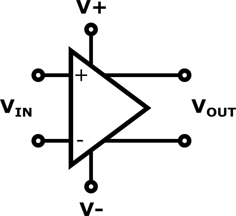
Common-Mode Rejection Ratio (CMRR) and Resistor Tolerance
The ability to reject common-mode signals is quantified by the common-mode rejection ratio. For difference amplifiers built from discrete resistors, CMRR depends entirely on matching the resistor ratios R2/R1 and R4/R3. A mismatch of even 0.1% can reduce CMRR by tens of decibels. Instrumentation amplifiers mitigate this issue by using internal laser-trimmed resistors with ratios matched to better than 0.01%, achieving CMRR of 90–120 dB at room temperature.
In difference amplifiers, CMRR degrades as gain increases because resistor ratio mismatches are amplified. Conversely, instrumentation amplifiers improve CMRR with increasing gain: decreasing the gain-setting resistor increases differential gain but leaves common-mode gain unchanged. When designing discrete instrumentation amplifiers, engineers must select resistors with tight tolerance and low temperature coefficient (0.1% or better) and match resistor ratios using networks or resistor arrays. Integrated instrumentation amplifiers eliminate this concern by trimming resistors during fabrication.
Input Impedance, Noise, and Common-Mode Range
Instrumentation amplifiers isolate the sensor through buffer stages, giving them very high input impedance compared with difference amplifiers. Selecting a device requires balancing voltage and current noise densities, which typically range from 7–9 nV/√Hz for popular parts. Power-supply range and common-mode handling also differ. Difference amplifiers can tolerate common-mode voltages far beyond the supply rails, whereas instrumentation amplifiers must operate within their supply range. Low-power in-amps like AD620 and LT1167 run from ±2.3 V, while higher-performance devices like INA128 or INA821 operate up to ±18 V and offer superior noise and CMRR.
Recommended reading: Understanding Noise Sources from GHz to nHz and How to Control Them
Real-World Difference Amplifiers Comparison
Many integrated difference amplifiers are available, each optimized for common-mode range, input impedance, and gain accuracy. Representative parts for high-side current sensing, battery monitoring, and differential signal conditioning:
Part | Common-mode range | Input impedance | Bandwidth | Key characteristics |
INA149 (TI) | ±275 V | 300 kΩ per input | 180 kHz | Handles ±500 V transients; excellent for high-side current sensing |
LT1991 (Analog Devices) | ±28 V | 500 kΩ per input | 550 kHz | Configurable gain via pin strapping (0.1×–10×) |
MAX4173 (Maxim) | 0–28 V | 70 kΩ per input | 500 kHz | Low-cost current-sense amplifier with internal gain (20 V/V) |
INA826 (TI) | ±18 V | 200 kΩ differential | 500 kHz | Two-op-amp instrumentation amplifier; good for bridge sensors |
These devices demonstrate how difference amplifiers handle wide common-mode ranges and various input impedances. Engineers select a part based on the expected common-mode voltage, desired gain, and sensor impedance. For high-impedance sources or when additional gain is needed, a discrete or integrated instrumentation amplifier is still required.
Difference Amplifier vs Instrumentation Amplifier
Although both topologies amplify the difference between two voltages, their architectures lead to different performance characteristics.
Feature | Difference amplifier | Instrumentation amplifier |
Architecture | Single op-amp with four resistors | Three op-amps: two buffers and a difference stage |
Gain adjustment | Fixed by resistor ratios; changing gain requires altering multiple resistors | Single resistor Rg sets gain over a wide range |
Input impedance | Moderate (tens to hundreds of kilohms) | Very high (mega-ohms to giga-ohms) due to buffers |
Common-mode range | Can exceed supply rails (depends on resistor network) | Limited to supply rails or slightly beyond; specialized architectures extend range |
CMRR | Depends on resistor matching; typically 80–100 dB for integrated devices | High; increases with gain; typically >100 dB |
Complexity and cost | Low component count and cost | Higher component count; integrated ICs simplify design |
Typical applications | High-side current sensing, battery monitoring, ground-loop isolation | Strain gauges, thermocouples, biopotential sensors, transducer front-ends |
In practice, engineers may combine both types: a difference amplifier can attenuate a high common-mode voltage, and an instrumentation amplifier can provide high gain and input impedance for subsequent low-level signal conditioning.
Choosing Between Difference and Instrumentation Amplifiers
Selecting the appropriate amplifier depends on sensor impedance, required gain, and common-mode voltage. Difference amplifiers suit low-impedance sources and signals riding on large common-mode voltages (for example, high-side current sensing) and offer low cost and simplicity. Instrumentation amplifiers are ideal for high-impedance sensors (strain gauges, thermocouples, RTDs, and biopotential electrodes) and microvolt-level signals requiring high gain and CMRR. Hybrid architectures such as the INA826 bridge the gap by handling moderate common-mode voltages while providing high input impedance and gain. Final selection also depends on power, bandwidth, and noise constraints.
Applications in Modern Electronics
Difference and instrumentation amplifiers are fundamental building blocks in modern analog electronics because they enable the accurate measurement of small differential signals in the presence of large common-mode voltages and electrical noise. Their ability to reject unwanted interference while amplifying the desired signal makes them indispensable in applications where precision, stability, and signal integrity are critical.
Difference amplifiers are widely used for current sensing in power electronics by measuring the small voltage drop across precision shunt resistors. In motor drives, switching power supplies, electric vehicles, and renewable energy systems, they monitor load current while rejecting the large common-mode voltages associated with high-side current sensing. They are also employed in battery management systems (BMS) to measure individual cell voltages and monitor battery stacks, enabling accurate state-of-charge estimation, cell balancing, over-voltage protection, and fault detection. In communication systems, difference amplifiers recover information transmitted over balanced differential signaling standards such as RS-485, CAN, LVDS, and Ethernet by rejecting common-mode noise induced along transmission cables, thereby improving communication reliability in electrically noisy industrial environments.
Instrumentation amplifiers extend these capabilities by providing very high input impedance, extremely high common-mode rejection ratio (CMRR), and precise, easily programmable gain, making them particularly suitable for low-level sensor interfacing. They are extensively used in medical instrumentation, including electrocardiogram (ECG), electroencephalogram (EEG), and electromyogram (EMG) systems, where microvolt- to millivolt-level biopotential signals must be amplified without loading the electrodes or introducing significant noise. Their high CMRR effectively suppresses 50/60 Hz mains interference and other environmental noise that can obscure physiological signals.
In industrial process control, instrumentation amplifiers serve as the front-end interface for sensors such as strain gauges, load cells, pressure transducers, thermocouples, resistance temperature detectors (RTDs), and bridge-based measurement circuits. They amplify very small sensor outputs before analog-to-digital conversion while maintaining excellent accuracy over wide temperature ranges. Precision data acquisition systems, programmable logic controllers (PLCs), and distributed control systems (DCS) rely on instrumentation amplifiers to ensure reliable measurements despite long cable runs, ground potential differences, and electromagnetic interference.
Beyond these traditional applications, modern difference and instrumentation amplifiers are increasingly integrated into Internet of Things (IoT) devices, wearable electronics, smart sensors, industrial automation, robotics, aerospace systems, and automotive electronics. They provide accurate signal conditioning for microcontroller and digital signal processor (DSP) analog-to-digital converters, enabling real-time monitoring of voltage, current, temperature, pressure, vibration, and other physical parameters. As modern electronic systems demand higher measurement accuracy, lower power consumption, and greater immunity to noise, these amplifiers continue to play a vital role in precision analog signal conditioning and measurement systems.
Market Trends and Future Outlook
The global market for precision difference and instrumentation amplifiers is experiencing sustained growth, driven by the increasing demand for high-accuracy analog signal conditioning in medical electronics, renewable energy systems, industrial automation, electric vehicles, and Internet of Things (IoT) devices. As modern electronic systems become more dependent on real-time sensing and data acquisition, the need for amplifiers capable of accurately measuring low-level differential signals in electrically noisy environments continues to increase. Advances in semiconductor fabrication technologies have also enabled manufacturers to produce amplifiers with lower offset voltage, reduced input bias current, improved temperature stability, and higher common-mode rejection ratio (CMRR), making them suitable for increasingly demanding applications.
One of the strongest growth drivers is the rapid expansion of the medical electronics industry, where instrumentation amplifiers are essential for patient monitoring systems, wearable health devices, diagnostic equipment, and implantable medical electronics. The increasing adoption of portable and battery-powered medical devices has created demand for amplifiers with ultra-low power consumption while maintaining high precision and low noise performance. Similarly, the growth of renewable energy technologies—including solar photovoltaic systems, wind turbines, and battery energy storage systems—has increased the use of precision difference amplifiers for current sensing, voltage monitoring, battery management, and power conversion applications.
Industrial automation and the transition toward Industry 4.0 are also accelerating market demand. Modern factories increasingly rely on smart sensors, programmable logic controllers (PLCs), distributed control systems (DCS), and predictive maintenance technologies, all of which require accurate analog front-end circuits for reliable data acquisition. Instrumentation amplifiers enable precise measurement of physical parameters such as pressure, temperature, vibration, strain, and flow, while rejecting electrical interference commonly found in industrial environments. Their integration into sensor modules and edge computing devices supports higher measurement accuracy and improved process control.
The automotive industry represents another major area of growth, particularly with the widespread adoption of electric vehicles (EVs) and advanced driver-assistance systems (ADAS). Precision amplifiers are extensively used for battery monitoring, motor current sensing, charging systems, and power management circuits, where high common-mode voltage capability and excellent measurement accuracy are essential for safety and energy efficiency. As vehicle electrification continues to expand worldwide, demand for high-performance difference and instrumentation amplifiers is expected to increase significantly.
Market analysts project that the global precision amplifier market will continue to grow steadily over the next decade, with overall sales expected to approximately double in response to increasing investments in healthcare, renewable energy, industrial automation, and intelligent electronic systems. Future amplifier designs are expected to emphasize lower power consumption, wider input common-mode voltage ranges, higher bandwidth, improved noise performance, enhanced electromagnetic interference (EMI) immunity, and greater integration with analog-to-digital converters (ADCs), digital signal processors (DSPs), and microcontrollers. Many modern devices already incorporate programmable gain, self-calibration features, diagnostic capabilities, and digital communication interfaces, reducing external component count while improving system reliability. These technological advancements position difference and instrumentation amplifiers as essential components in the next generation of precision measurement, control, and intelligent sensing systems.
Conclusion
Difference amplifiers and instrumentation amplifiers are essential components in precision analog circuit design because they enable the accurate amplification of differential signals while minimizing the effects of common-mode noise and interference. Although both amplifier types perform differential signal amplification, they serve different design requirements. Difference amplifiers provide a simple, cost-effective solution for applications such as current sensing, voltage monitoring, and balanced signal reception, whereas instrumentation amplifiers incorporate input buffer stages to achieve very high input impedance, adjustable gain, and excellent common-mode rejection ratio (CMRR). Selecting the appropriate amplifier depends on factors such as source impedance, common-mode voltage, required gain, bandwidth, noise performance, power consumption, and measurement accuracy. Careful attention to resistor matching, printed circuit board (PCB) layout, grounding, shielding, and power supply decoupling is also essential to achieve the expected level of precision.
The availability of highly integrated devices such as the INA128, AD620, LT1167, and INA821 has greatly simplified the design of high-performance analog front-end circuits by providing laser-trimmed resistor networks, low offset voltage, and excellent gain stability within a single integrated circuit. These features reduce design complexity while improving measurement accuracy and long-term reliability. As technologies such as electric vehicles, renewable energy systems, Industry 4.0, Internet of Things (IoT) devices, wearable medical electronics, and industrial automation continue to expand, the demand for accurate and reliable signal conditioning will also increase. Consequently, difference and instrumentation amplifiers will remain indispensable building blocks in modern electronic systems, enabling engineers to develop precise, robust, and efficient measurement solutions for an increasingly connected and data-driven world.
Frequently Asked Questions
Why is common-mode rejection important?
Common-mode signals such as ground offsets and electromagnetic interference distort differential measurements. A high CMRR ensures that the amplifier suppresses these unwanted signals so only the differential voltage appears at the output.
Can difference amplifiers handle common-mode voltages beyond their supply rails?
Yes. Properly scaled resistor networks allow difference amplifiers to tolerate common-mode voltages far exceeding the op-amp's supply voltage. Instrumentation amplifiers, however, operate within or slightly beyond their supply rails.
When should I use a difference amplifier instead of an instrumentation amplifier?
Use a difference amplifier when the signal rides on a large common-mode voltage and the source impedance is low. Use an instrumentation amplifier when the source has high impedance or when microvolt-level signals require high gain.
What is the difference between an instrumentation amplifier and an op-amp?
An op-amp is a general-purpose amplifier. An instrumentation amplifier is a specific three-op-amp configuration with matched resistors that provides high input impedance, single-resistor gain control, and high CMRR.
How do I choose between INA128, AD620, and LT1167?
Compare supply voltage, gain range, noise, and power. INA128 offers wide supply voltages and high CMRR. AD620 is low power and popular in medical instrumentation. LT1167 minimizes power consumption but has slightly lower CMRR. Choose the device that best matches your sensor and performance requirements.
References
Texas Instruments, A Guide for Designing with Instrumentation Amplifiers (3rd ed.). Dallas, TX, USA: Texas Instruments, 2006. [Online]. Available: https://www.ti.com/lit/an/sboa092b/sboa092b.pdf
P. Horowitz and W. Hill, The Art of Electronics, 3rd ed. Cambridge, U.K.: Cambridge University Press, 2015
Analog Devices, A Designer's Guide to Instrumentation Amplifiers, 3rd ed. Wilmington, MA, USA: Analog Devices. [Online]. Available: https://www.analog.com/media/en/training-seminars/design-handbooks/designers-guide-instrument-amps-complete.pdf
S. Franco, Design with Operational Amplifiers and Analog Integrated Circuits, 4th ed. New York, NY, USA: McGraw-Hill Education, 2014.
J. Huijsing, Operational Amplifiers: Theory and Design. Cham, Switzerland: Springer, 2017. [Online]. Available: https://link.springer.com/book/10.1007/978-3-319-28127-8
L. Ssafari, G. Ferri, S. Minaei, and V. Stornelli, "Principles of Instrumentation Amplifiers," in Current-Mode Instrumentation Amplifiers. Cham, Switzerland: Springer, 2019, pp. 1–13. [Online]. Available: https://link.springer.com/chapter/10.1007/978-3-030-01343-1_1
B. Carter and R. Mancini, Op Amps for Everyone, 5th ed. Oxford, U.K.: Elsevier, 2018. [Online]. Available: https://shop.elsevier.com/books/op-amps-for-everyone/carter/978-0-12-811648-7
in this article
1. Key Takeaways2. Introduction3. Instrumentation Amplifier Fundamentals4. Classic Three-Op-Amp Circuit5. The Gain-Setting Resistor Rg6. Transfer Function Derivation7. Why Three Op-Amps Beat the Difference Amplifier8. Instrumentation Amplifier ICs: INA128, AD620, LT11679. Sensor Interface Applications10. Industrial Current Sensing11. Common-Mode Rejection Ratio (CMRR) and Resistor Tolerance12. Input Impedance, Noise, and Common-Mode Range13. Real-World Difference Amplifiers Comparison14. Difference Amplifier vs Instrumentation Amplifier15. Choosing Between Difference and Instrumentation Amplifiers16. Applications in Modern Electronics17. Market Trends and Future Outlook18. Conclusion19. Frequently Asked Questions20. References