Inductor in Series: Comprehensive Analysis for Digital and Hardware Engineers
This in depth article explores the theoretical foundation and practical considerations of connecting inductor in series for engineers and electronics students. Learn how series inductance works, why it increases total inductance, how mutual coupling affects it and how to design effective filters.

02 Mar, 2026. 10 minutes read
Key Takeaways
When several inductors share the same current, their voltage drops add, and the equivalent inductance is the sum of individual inductances. Coupled inductors require additional terms for mutual inductance.
Inductors store magnetic energy. In an RL series circuit, the transient response depends on the time constant.
Selecting inductance, current ripple, and saturation current influences efficiency, transient response and electromagnetic interference. Typical ripple targets of 10–30 % of load current balance efficiency and response. High inductance reduces ripple but slows transient response and increases size.
Real inductors exhibit winding resistance, core losses, self‑resonant frequency (SRF), and parasitic capacitance. These factors determine usable frequency range and quality factor Q.
Series inductors serve as chokes in low‑pass filters, energy storage elements in buck converters and timing components in RL networks. Design examples illustrate these roles.
Introduction
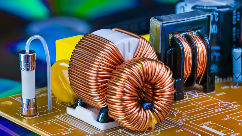
Inductors are fundamental building blocks in electronic systems. They store energy in a magnetic field when current flows and resist changes in that current. When inductors are connected in series—such that the same current flows through each coil—their individual voltage drops add. This inductor in series configuration appears in applications ranging from power supplies to signal filters and sensor conditioning.
Understanding how series connection influences total inductance, energy storage, transient response, and practical performance is essential for digital design engineers, hardware engineers, and electronics engineering students.
This article offers a comprehensive exploration of series inductors. We first revisit electromagnetic principles to explain why inductance adds in series and how mutual coupling modifies the equivalent inductance. We then analyze the transient behavior of RL circuits and energy storage. Practical sections examine parasitic elements, core saturation, selecting inductors for filters and converters and using series inductors for noise suppression. Tables and figures illustrate concepts, and frequently asked questions address common design challenges.
Fundamentals of Inductance
Magnetic Fields and Faraday’s Law
An inductor typically consists of a coil of wire wound around a core. When current i(t) flows through the coil, it generates a magnetic field proportional to the current.
According to Faraday’s law, a time‑varying magnetic flux through a closed loop induces a voltage:

where N is the number of turns, and Φ is the magnetic flux linkage.
For linear magnetic materials, flux is proportional to current, and the constant of proportionality is the inductance L. Thus, the voltage across an ideal inductor obeys

Energy Storage
Inductors store energy in the magnetic field rather than dissipating it. The energy stored at current I is given by

This expression arises by integrating the instantaneous power

with respect to current. Because energy scales with the square of current, doubling the current quadruples the energy stored.
Inductance of SimpleSolenoids
For a long solenoid of length l and cross‑sectional area A, with N turns on a core of magnetic permeability μ, the inductance is approximated by:

Real inductors deviate from this ideal due to core geometry, fringing fields and parasitic capacitance, but the relation highlights that increasing turns or using a high‑permeability core boosts inductance.
Series Connection of Inductors
Equivalent inductance for uncoupled coils
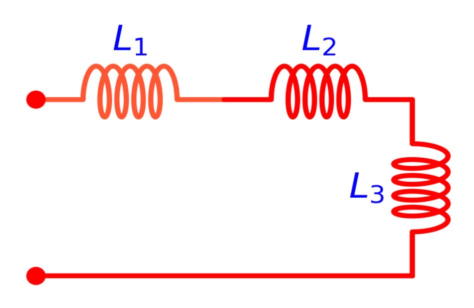
Consider three inductors L1,L2, and L3 connected in series. Because the same current flows through each coil, the voltages across them add:
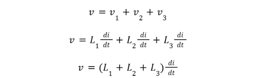
Hence, the equivalent inductance of inductors in series is

This simple additive property applies when the magnetic fields of the inductors do not interact—i.e., there is negligible mutual coupling. Connecting inductors in series results in a total inductance greater than any single inductor, whereas parallel connections yield smaller equivalent inductance.
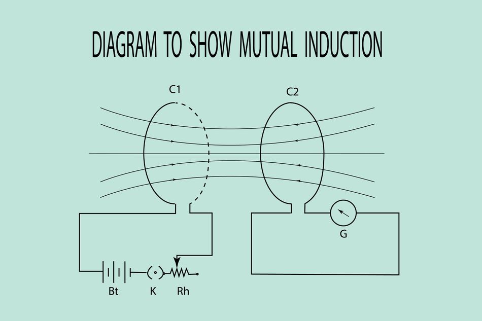
Effect of Mutual inductance
If inductors are physically close, their magnetic fields interact via mutual inductance M. For two coupled coils, the total voltage across the series combination depends on the direction of the winding and the coupling factor k. The equivalent inductance is given by

The sign depends on whether the coils aid or oppose each other’s magnetic field. When the dot conventions indicate cumulative coupling (series aiding), the inductance increases by +2M.
For differential coupling (series opposing), the mutual term subtracts, potentially reducing equivalent inductance. In multi‑coil arrangements, mutual coupling terms appear between each pair, making the calculation more complex.
Series Connection with Significant Coupling
In practice, designers sometimes exploit coupling intentionally. For example, in transformers or coupled inductors used in resonant converters, the mutual inductance is essential for power transfer and isolation.
However, unintended coupling between inductors on a crowded PCB can alter circuit behavior. Minimizing mutual inductance through physical spacing or orthogonal orientation helps maintain predictable series inductance.
Recommended Reading: PCB Components: A Comprehensive Technical Guide to Passive, Active, and Electromechanical Parts
RL Series Circuit: Transient Response
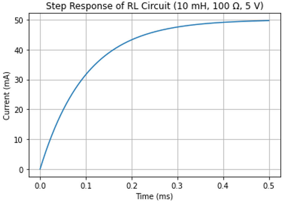
When an inductor in series with a resistor is driven by a step voltage, the current does not rise instantly. Instead, the inductor resists changes in current, and the current follows an exponential trajectory. For a series RL circuit with inductance L and resistance R connected to a constant voltage source V, the current response is:

The time constant τ characterizes how quickly current approaches its steady‑state value. After one time constant, the current reaches about 63 % of its final value, and after five time constants it is close to 99 %. Larger inductance or smaller resistance results in a larger time constant and slower transient response.
Step response graph
The graph below shows the current response of a 10 mH inductor in series with a 100 Ω resistor driven by a 5 V step. The time axis is in milliseconds and the current is plotted in milliamperes.
Practical Implications
Understanding the RL time constant is critical in timing and filtering applications. For example, in a digital input network, adding an inductor in series with a resistor can slow down the rise time of a noisy signal, acting as a low‑pass filter.
Conversely, in switching power converters, a larger inductance slows the converter’s response to load transients, potentially leading to undervoltage or overshoot if the control loop is not tuned appropriately.
Energy Storage and Magnetic Saturation
Magnetic Energy and Flux Density
As derived earlier, the energy stored in an inductor grows with the square of current. However, real inductors have cores with finite magnetic permeability. When the magnetic flux density reaches a material‑dependent limit, the core saturates.
Beyond this point, additional current does not yield proportional increases in magnetic flux. In core saturation, little or no voltage is induced across the inductor, and it behaves more like a resistor or short circuit. Designers must limit peak current to avoid saturation, or choose cores with higher saturation flux density.
Choosing an inductor’s current rating
Datasheets specify an inductance value, saturation current (current at which inductance drops by a defined percentage) and ripple current rating. For power converters, the ripple current (AC component of inductor current) is typically 10–30 % of the load current, providing a compromise between efficiency and transient response.
When current peaks exceed the saturation current, the inductor no longer behaves linearly and may distort waveforms or cause electromagnetic interference (EMI).
Quality Factor and Self‑resonant Frequency
Real inductors possess parasitic series resistance (ESR) due to wire resistance and core losses. The quality factor Q measures how “ideal” an inductor is:

where XL is the inductive reactance. Higher Q indicates lower resistance relative to reactance, leading to lower energy loss in resonant circuits. Additionally, inter‑turn capacitance yields a self‑resonant frequency (SRF) at which the inductive and capacitive reactances cancel.
Above the SRF, the inductor behaves capacitively and cannot provide inductive impedance. Selecting an inductor with an SRF well above the operating frequency ensures proper operation.
Suggested Reading: Calculate Impedance in AC Circuits: A Comprehensive Guide for Engineers
Practical Implementation and Design Considerations
Selecting Series inductors for Filters
One common use of inductors in series is chokes—inductors placed in series with a signal or power line to block or attenuate high‑frequency components. In low‑pass LC filters, the inductor in series works with a capacitor in parallel to form a frequency‑selective network.
According to a Coilcraft technical paper, high inductance values filter low‑frequency noise while lower inductance values target higher‑frequency noise. When designing filters:
Determine cutoff frequency: In a first‑order LC low‑pass filter, the cutoff frequency is

Larger inductance lowers the cutoff, but increases size and series resistance.
Check ripple and current rating: Ensure the inductor can handle the maximum current without saturating. High ripple current requires larger cores or toroidal inductors.
Parasitic effects: At high frequencies, parasitic capacitance can cause the inductor to resonate. Choose an inductor with SRF above the highest frequency of interest.
Series inductors in DC–DC converters
Switching regulators, such as buck and boost converters, rely on inductors to store energy and transfer it between input and output. In a buck converter, the inductor in series with the load smooths the pulsed current from the switching transistor. Design guidelines include:
Inductance selection: Too low an inductance increases ripple current and core losses, while too high an inductance slows transient response and requires larger components. A ripple current of 20–40 % of output current offers a balance.
Saturation current: Choose an inductor whose saturation current exceeds the maximum peak current (average + half ripple). Derate by 20–30 % for temperature and manufacturing variance.
Core material: Ferrite cores offer low losses at high frequencies, while powdered iron cores provide higher saturation current but larger losses at high frequency.
Coupled inductors: In some topologies, such as SEPIC converters, coupled inductors allow energy sharing between two windings.
Noise suppression and EMI considerations
Inductors in series can suppress electromagnetic interference by impeding high‑frequency noise. These series chokes appear on power supply lines, USB interfaces and sensor inputs. Design considerations include:
Parameter | Impact on EMI suppression | Typical value range |
Inductance | Determines impedance at noise frequencies. Higher inductance attenuates lower frequencies. | 10 µH – 10 mH |
DC Resistance (DCR) | Causes voltage drop and heat. Keep low to avoid significant loss. | 10 mΩ – 1 Ω |
Saturation current | Must exceed worst‑case load current to prevent distortion. | 100 mA – 10 A |
SRF | Should exceed the highest noise frequency to ensure inductive behavior. | 1 MHz – 100 MHz |
Minimizing parasitic effects in layout
Layout affects series inductance performance. Keep traces short to minimize stray resistance and capacitance, and avoid placing inductors close to high‑frequency switching edges that can couple noise.
If using multiple inductors in series, orient them orthogonally or separate them physically to reduce unintended mutual coupling. Shielded inductors reduce magnetic field emission and susceptibility to external fields.
Advanced Topics
Multi‑Stage Filter Design
When a single inductor does not provide sufficient attenuation, multiple inductors can be connected in series with capacitors between stages. Each stage increases the filter order and steepens the roll‑off.
However, designers must consider cumulative resistance and core losses. For a second‑order LC filter, the transfer function is:

Increasing L reduces the cutoff frequency but increases the damping ratio due to R/L, which can affect the transient response. A careful balance yields a filter with acceptable attenuation and minimal overshoot.
Suggested Reading: Extending the Battery Life of Hearables and Wearables with Single-Inductor Multiple-Output Switching Architecture
Resonant Circuits and Impedance Matching
Series inductors, when combined with capacitors and resistors, form resonant networks used in oscillators, impedance matching and RF design. In a series RLC circuit, the impedance is minimum at the resonant frequency:

The quality factor Q determines the sharpness of the resonance. Real inductors with low Q broaden the resonance and dissipate more energy. In coupled resonators, mutual inductance introduces additional resonant modes. Engineers must account for these interactions when designing matching networks or wireless power transfer systems.
Digital design perspective
While digital circuits are often dominated by logic gates and ICs, analog passive components like inductors play important roles in mixed‑signal interfaces. Series inductors can isolate digital switching noise from analog sensor inputs or provide controlled rise/fall times for clock signals.
When designing high‑speed digital interfaces, series inductors can be part of termination networks that match the transmission line impedance and reduce reflections. Selecting inductors with appropriate SRF and minimal parasitic capacitance ensures the digital edges are not excessively slowed.
Conclusion
Series inductors are versatile components that extend beyond simple energy storage. The additive property of inductance, whether for uncoupled coils or with mutual coupling, underpins their behavior in filters, regulators and resonant networks. Understanding the time constant in RL circuits informs timing and transient response, while awareness of core saturation, quality factor and self‑resonant frequency ensures designs remain reliable across operating conditions.
Practical design involves balancing ripple current, transient response, EMI suppression and parasitic effects. By following the guidelines and formulas presented here, engineers can confidently incorporate inductors in series into a wide range of applications.
FAQ
1. What is the equivalent inductance of inductors in series?
For uncoupled inductors carrying the same current, the equivalent inductance is simply the sum of the individual inductances: Leq=L1+L2+⋯Ln.
2. How does mutual inductance affect series inductors?
When inductors are magnetically coupled, the equivalent inductance becomes L1+L2±2M where M is the mutual inductance. The sign depends on whether the windings aid (plus) or oppose (minus) each other’s flux. Strong coupling can significantly increase or reduce total inductance.
3. Why is the time constant important in an RL circuit?
The time constant τ=L/R determines how quickly current in an RL series circuit reaches steady state. After one time constant, the current is about 63 % of its final value; after five time constants, it is near 99 %. This parameter guides designers in setting response times for filters and power converters.
4. What happens when an inductor saturates?
When magnetic flux density exceeds the core’s capability, the inductance drops dramatically. In saturation, the inductor no longer stores additional energy and behaves like a low‑impedance element. Exceeding the specified saturation current can therefore distort waveforms and reduce efficiency.
5. How do I choose an inductor for a buck converter?
Select an inductance that yields a ripple current between 10 % and 40 % of the load current. Ensure the saturation current exceeds the peak current by a safety margin, and choose a core material that provides low loss at the switching frequency. Also verify that the SRF is above the switching and ripple frequencies.
6. What are some strategies to reduce mutual coupling between series inductors on a PCB?
Separate inductors physically, orient them at right angles to each other and use shielded cores. This reduces unintended mutual inductance, ensuring that series inductance remains the intended sum.
References
All About Circuits, “Series and Parallel Inductors,” Electronics Textbook, 2021. [Online]. Available: https://www.allaboutcircuits.com/textbook/direct-current/chpt-15/series-and-parallel-inductors/.
DCACLab, “Inductors in Series Explained in Detail,” DCACLab Blog, May 12, 2020. [Online]. Available: https://dcaclab.com/blog/inductors-in-series-explained-in-detail/.
Electronics Tutorials, “Inductors,” Electronics-Tutorials.ws. [Online]. Available: https://www.electronics-tutorials.ws/inductor/inductors.html
EEE Guide, “Inductors in Series.” [Online]. Available: Series Connection of Coupled Inductors
Coilcraft, “Inductor Basics.” [Online]. Available: Fundamentals of Power Inductors | Coilcraft
Analog Devices, “Buck Converter Design,” Application Notes. [Online]. Available: Buck Power Stage Design Equations | Analog Devices
All About Circuits, “Inductor Core Saturation,” Electronics Textbook. [Online]. Available: https://www.allaboutcircuits.com/technical-articles/controlling-and-preventing-core-saturation-in-inductors/