Hall Effect Current Sensor: Principles, Topologies and Engineering Applications
Learn how a Hall Effect Current Sensor works, including principles, topologies, specifications, comparisons and engineering applications.

03 Jul, 2026. 15 minutes read
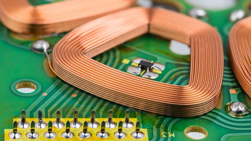
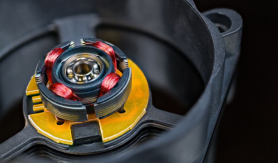
Copper Wire Winding with Hall Effect Sensor on Green PCB inside Engine with Electronic Commutation
Key Takeaways
Galvanic Isolation and Non-Intrusive Measurement: Hall effect current sensors measure AC and DC currents without interrupting the conductor, providing safety isolation between the high-voltage current path and the low-voltage output circuit.
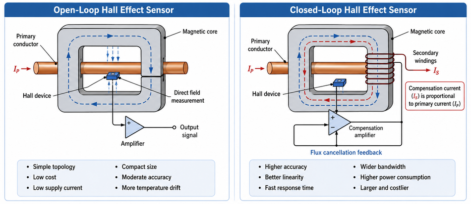
Open-Loop vs Closed-Loop: Open-loop sensors sense the magnetic field directly with a Hall plate and offer simplicity, low cost, and small size, while closed-loop sensors drive a secondary winding to null the flux, achieving higher accuracy, wider bandwidth, and lower drift.
Integrated Solutions: Modern ICs such as ACS712 or TMCS1100 integrate a low-resistance current conductor and Hall plate on a single chip, offering 80 kHz signal bandwidth, response times of a few microseconds and isolation ratings up to 3 kVrms.
Comparison with Other Sensing Methods: Hall effect current sensors provide isolation and DC capability, unlike current transformers and Rogowski coils. They dissipate far less power than shunt resistors and offer better low-frequency performance than Rogowski coils, but their accuracy and bandwidth are lower than those of closed-loop fluxgate or DC-CT sensors.
Applications across Power Electronics: Engineers use Hall effect current sensors in motor drives, photovoltaic inverters, battery management systems, electric vehicle chargers, and overcurrent protection. They enable accurate current feedback for control loops and provide isolation for safety and electromagnetic compliance.
Introduction
The current measurement is fundamental in power electronics, motor control and instrumentation. Engineers often need to measure currents from milliamps to kiloamps while balancing accuracy, isolation, bandwidth, thermal performance, and cost. Traditional methods such as shunt resistors and current transformers face trade-offs: shunts dissipate power and lack isolation; transformers cannot measure DC and saturate at low frequencies. Hall Effect Current Sensor overcomes these limitations by exploiting the Hall effect, where a voltage develops perpendicular to both the current flow and an applied magnetic field. The Hall voltage is directly proportional to the magnetic flux density and, hence, to the primary current.
Hall effect current sensor may use open-loop or closed-loop architectures, depending on the required precision, response time, and linearity. This article explains the operating principles of a Hall effect current sensor, compares key topologies, reviews key datasheet specifications, and explores practical design considerations. The examples from real devices illustrate performance parameters.
Operating Principle of the Hall Effect Current Sensing
Hall Effect and Hall Voltage
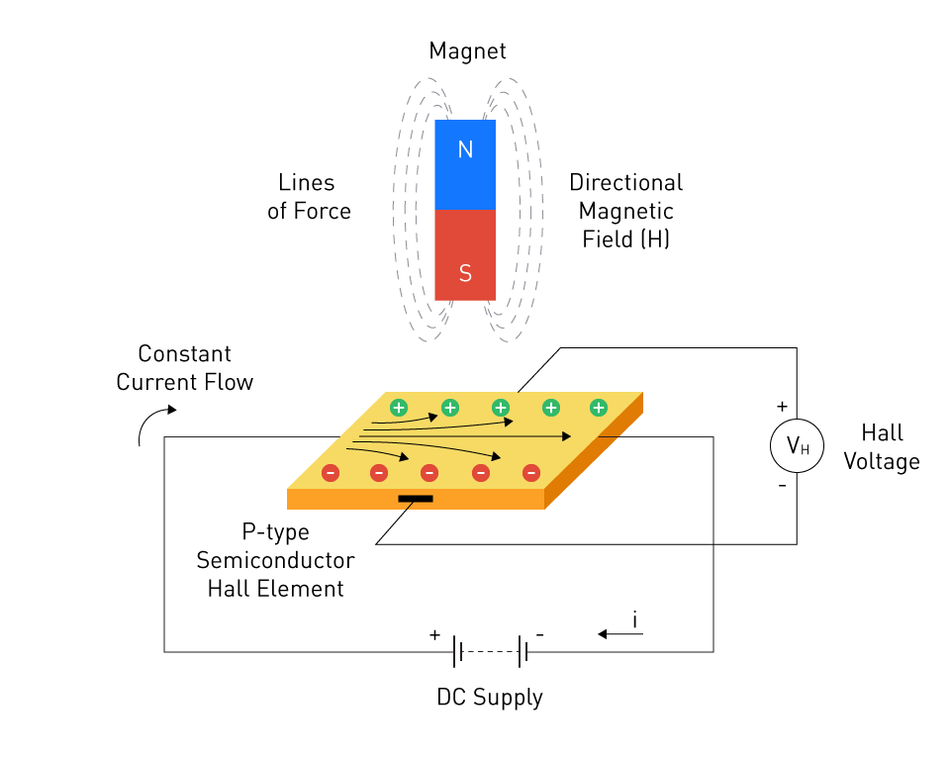
The Hall effect occurs when an electric current flows through a conductor in the presence of a magnetic field perpendicular to the current. Charge carriers experience the Lorentz Force: F = q(v × B), which deflects them to one side of the conductor and generates a transverse voltage, the Hall voltage (V). For a Hall plate of thickness (t) carrying current (Ic) and exposed to magnetic flux density (B), the Hall voltage is
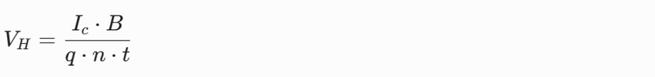
where q is the elementary charge and n is the charge carrier density. In practical Hall ICs, the raw Hall voltage is only a few microvolts, so an integrated amplifier boosts it to a usable level.
Magnetic Field from Current
According to Ampere's law, the magnetic field around a straight conductor of current (I) at a distance (r) is
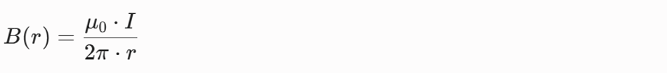
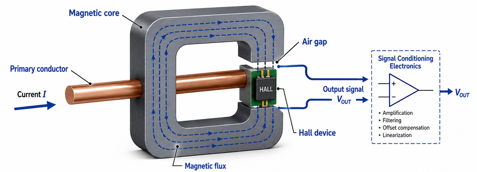
where μ ≈ 4π × 10-7 H/m is the permeability of free space. In current sensors, the conductor passes through a magnetic core or an integrated conductor loop. The core concentrates the magnetic flux into a small gap where the Hall element resides, increasing sensitivity. Some integrated sensors use on-chip current paths and magnetic concentrators rather than ferrite cores.
Galvanic Isolation and Non-Intrusive Measurement
Because the Hall element senses the magnetic field rather than sampling the voltage drop, the high-voltage current path is electrically isolated from the sensor output. The open-loop and closed-loop Hall current sensors provide galvanic isolation while measuring complex AC and DC waveforms [1]. The isolation rating is specified as the maximum working voltage and isolation withstand voltage, typically ranging from hundreds of volts to several kilovolts. For example, the ACS712 has 2.4 kVrms isolation and a low 1.2 mΩ conductor resistance [3]. TMCS1100 provides 3 kVrms isolation and supports a 600 V working voltage [4].
Recommended Reading: Comprehensive Technical Guide to Hall Effect Sensors
Open-Loop vs Closed-Loop Hall Effect Current Sensors
Hall effect current sensors fall into two main categories: open-loop and closed-loop (also called compensated or zero-flux) topologies. Both sense magnetic flux with a Hall element but differ in how they process the signal and control the magnetic field.
Open-Loop Topology
In an open-loop Hall effect sensor, the Hall plate measures the magnetic field produced by the primary current. The output from the sensor is an amplified analog voltage or current proportional to the magnetic field and therefore to the current. The open-loop sensor consists of a ferromagnetic core with a gap, a Hall transducer in the gap and an amplifier. Any nonlinearity or drift in the Hall element with temperature directly affects accuracy, as the sensor operates without feedback [2].
Open-loop sensors offer several benefits:
Simple Construction: They use a single Hall element and amplifier, resulting in low cost and compact size.
Low Power Consumption: There is no secondary coil to drive, so supply current is typically only a few milliamps.
Wide Current Range: By appropriately designing the core geometry, open-loop sensors can measure currents from a few amperes to several kiloamperes. The open-loop designs are especially advantageous for high currents above 300 A [1].
Low Insertion Loss: The primary conductor passes through the sensor with minimal resistance, avoiding voltage drop and heat buildup.
However, open-loop sensors have limitations:
Moderate Accuracy and Linearity: Gain drift and offset drift lead to errors. Allegro's open-loop ACS712 IC has a total output error of around ±1.5% at 25 °C [3].
Limited Bandwidth: Typical bandwidth is tens to hundreds of kilohertz. The ACS712 offers an 80 kHz bandwidth with a 5 µs rise time [3]; newer sensors like the TMCS1100 achieve 80 kHz but remain constrained by Hall-element dynamics. [4]
Sensitivity to External Fields: Stray magnetic fields or mechanical stress can introduce offset errors. Coreless ICs often integrate shielding to improve common-mode rejection.
Open-loop Hall sensors are well-suited to general-purpose current monitoring, battery chargers, and power supplies, where modest accuracy is acceptable, and cost and board space are constrained.
Closed-Loop (Compensated or Zero-Flux) Topology
Closed-loop Hall effect sensors improve accuracy by adding a secondary compensation winding. The Hall element senses the flux in the magnetic core and feeds a servo amplifier that drives a current through the secondary winding to cancel (zero) the flux. The compensation current in the secondary is proportional to the primary current. Measuring this compensation current through a resistor yields an output voltage proportional to the primary current. Because the Hall element operates near zero flux, its nonlinearity and temperature drift have minimal effect on accuracy [2].
Closed-loop sensors offer several advantages:
High Accuracy and Linearity: The closed-loop sensors by VAC achieve an accuracy of 0.4%-0.7% with negligible temperature drift [6]. TMCS1100 (though an open-loop IC) achieves a typical total error of ±0.4 %.
Wide Bandwidth and Fast Response: The frequency response extends from DC to 200 kHz for standard closed-loop modules. Some devices offer bandwidths exceeding 1 MHz for precision AC measurements.
Low Offset Drift: Because the Hall element senses zero net flux, offset and drift are minimized. The secondary control ensures good temperature stability.
Output Current: The output is typically a current proportional to the primary current (through the compensation winding), making it less susceptible to noise and more flexible for scaling.
The trade-offs of closed-loop sensors include:
Larger Size and Higher Cost: The secondary coil and servo amplifier increase package size and complexity, leading to higher cost and greater board area requirements.
Increased Power Consumption: The compensation coil draws current proportional to the measured current, especially at high currents, resulting in higher supply requirements.
Limited Output Voltage Swing: The internal voltage drops across the compensation coil and amplifier limit the output range.
Closed-loop Hall sensors are the preferred choice in precision motor control, inverter control loops, and protective relays where accuracy and dynamic response outweigh cost and size.
Comparing Open-Loop and Closed-Loop Sensors
The concise comparison of the two topologies is presented below:
Open-Loop Hall Sensors are generally simpler, smaller, and more economical. They typically provide a total accuracy of ±1–3% at room temperature, although their output may drift with temperature and in the presence of external magnetic fields. Their bandwidth typically extends from DC to about 50–120 kHz [7]. This makes them suitable for general current monitoring, battery systems, motor drives, and power electronics applications where moderate accuracy is acceptable. Because they consume only a few milliamps of supply current and can be implemented as compact coreless ICs or small modules, open-loop sensors are widely used in cost-sensitive designs.
Closed-Loop Hall Sensors offer higher accuracy, better linearity, and faster dynamic response. They typically achieve an accuracy of ±0.4–0.7% and bandwidths from DC to 200 kHz or higher [6]. In this topology, a compensation coil actively cancels the magnetic flux generated by the primary current, allowing the sensor to maintain excellent linearity over a wide measurement range. However, this approach requires more power, a larger package, and a higher overall cost. Closed-loop sensors are therefore preferred in precision current measurement, servo drives, laboratory equipment, inverters, and other applications where accuracy and fast response are more important than size or cost.
Recent advances in IC packaging, integrated current conductors, and digital compensation are also narrowing the performance gap, allowing some open-loop sensors to approach closed-loop accuracy in compact designs.
Recommended Reading: What is a Sensor? In-Depth Exploration and Comprehensive Guide to Engineering Principles and Applications
Integrated and Coreless Hall Effect Current Sensors
Advances in semiconductor processing and packaging have enabled monolithic Hall effect current sensors that integrate the current conductor and Hall plate on a single chip. These coreless sensors eliminate the need for an external magnetic core and coil, reducing size and cost while still providing isolation.
Allegro - ACS712 Family
The ACS712 is a widely used open-loop Hall IC available in ±5 A, ±20 A, and ±30 A ranges. According to the datasheet [3], it features:
Low-Noise Analog Signal Path and Chopper-stabilised Amplifier.
Bandwidth is set via an External Filter Pin, with 5 µs Rise Time and 80 kHz Bandwidth.
Total Output Error of 1.5% at 25 °C.
Output Sensitivity from 66 mV/A to 185 mV/A, depending on the Range.
2.4 kVrms Isolation and 1.2 mΩ Conductor Resistance enable Continuous Currents up to 30 A with Minimal Power Dissipation.
These sensors provide ratiometric outputs (0.5 × Vcc at zero current) and are ideal for microcontroller-based current monitoring, motor control and battery systems where moderate accuracy is acceptable.
TI - TMCS1100
TMCS1100 by Texas Instruments is a precision Hall-effect current-sensor IC designed for high accuracy. According to the datasheet [4], it features:
Total Error ±0.4% Typical and ±0.9% Maximum from -40 °C to 85 °C.
Sensitivity Error ±0.4% and Linearity Error 0.05%.
Offset Error 7 mA with Drift 0.04 mA/°C.
Isolation Rating: 3 kVrms and Working Voltage: 600 V
Signal Bandwidth of 80 kHz with Options for 50, 100, 200 and 400 mV/A Sensitivities.
Low 1.8 mΩ Internal Conductor minimizing Insertion Loss and Heat.
TMCS1100 demonstrates how advanced analog design and calibration deliver near closed-loop performance in an open-loop IC. Its high accuracy and temperature stability make it suitable for precision inverters, server power supplies and motor drives.
Integrated Module Sensors
Many manufacturers offer Hall effect current sensor modules with integrated ferromagnetic cores and signal conditioning. These can handle hundreds or thousands of amperes and provide voltage or current outputs. Modules such as the HO series by LEM or closed-loop sensors by VAC include packaged cores with slots for the busbar and connectors for power and signal. They are often used on DC bus links, inverter outputs and battery cables in electric vehicles.
Comparison with Other Current-Sensing Technologies
Hall effect sensors are not the only option for measuring current. Engineers must consider other methods depending on measurement range, frequency and isolation requirements.
Compared with other technologies, Hall effect sensors provide a practical balance between isolation, bidirectional AC/DC measurement, compact packaging, and moderate cost.
Shunt Resistor with an amplifier is the simplest and lowest-cost current-sensing method. It can measure both AC and DC current and typically supports bandwidths from DC to around 10 MHz. [7] However, shunt sensing does not inherently provide galvanic isolation, dissipates power through the resistor, and may require an isolation amplifier for high-side or high-voltage measurements. Its typical accuracy is around ±3–5%, making it suitable for low-cost applications where insertion loss and isolation are manageable.
Open-Loop Hall Sensors provide galvanic isolation and can measure both AC and DC currents. [1] Their bandwidth typically extends from DC to about 50–120 kHz, with current ranging from a few amperes to several kiloamperes. They are compact, low-power, and relatively economical, making them attractive for motor drives, battery systems, inverters, and general current monitoring. However, their accuracy is usually lower than that of precision transducers, often around ±2–10%, and their output may drift with temperature or be affected by external magnetic fields.
Closed-Loop Hall Sensors improve accuracy, bandwidth, and linearity by using a compensation coil to cancel the magnetic flux generated by the primary current. They can measure AC and DC currents with typical accuracy around ±0.4–0.7% and bandwidths from DC to 200 kHz or higher. [6] This makes them suitable for precision drives, power converters, laboratory equipment, and fast-response control systems. The trade-off is higher power consumption, larger package size, and greater cost compared with open-loop Hall sensors.
Current Transformers provide galvanic isolation and are widely used in power metering and AC current monitoring. They can measure currents from several amperes to thousands of amperes, with typical accuracy around ±3–5%. However, CTs measure only AC and cannot detect DC. Their performance is also limited by core saturation, burden resistor selection, and frequency range, which may extend from power-line frequencies to around 1 MHz in suitable designs.
Rogowski Coils are flexible, non-intrusive sensors that measure the rate of change of current rather than current directly. They are well suited for high-current conductors, pulsed currents, and high-frequency transient measurement, with bandwidths extending from above 100 kHz into the MHz range. Because they produce a signal proportional to di/dt, they require an integrator to reconstruct the current waveform. Rogowski coils provide isolation and excellent high-frequency response, but they cannot measure DC current, and their accuracy depends strongly on coil construction and integrator quality.
Fluxgate and Zero-Flux DC-CT Transducers offer the highest precision among isolated current-sensing technologies. They can measure both AC and DC currents, often with accuracy from 0.1% down to 0.01% and bandwidths from DC to more than 750 kHz. [5] These sensors provide very low drift and excellent linearity, making them suitable for metrology, high-end power analysis, precision test equipment, and advanced power conversion systems. However, they are more complex, larger, and significantly more expensive than Hall effect sensors.
Overall, Hall effect sensors occupy the middle ground between simple shunt resistors and more complex fluxgate or DC-CT transducers. They offer isolation and the ability to measure DC, making them versatile for many power electronics applications. However, their accuracy and bandwidth are lower than those of closed-loop fluxgate devices, and they may need shielding against external fields.
Recommended Reading: Overcoming Complexity Challenges in PCB Design with Magnetic Current Sensors
Key Specifications and Datasheet Parameters
When selecting a Hall-effect current sensor, engineers must examine the datasheet parameters to ensure the device meets system requirements.
The important specifications include:
Current Range: The maximum continuous and peak currents the sensor can measure. For example, the ACS712 has ±5, ±20 and ±30 A variants, while module sensors can handle thousands of amperes.
Sensitivity (mV/A or mA/A): The output change per ampere of current. The TMCS1100 offers 50, 100, 200 or 400 mV/A options. Higher sensitivity improves resolution but reduces the measurable range.
Total Error and Accuracy: Includes offset, gain and linearity errors across temperature. The total output error of ACS712 is 1.5% at 25 °C, while TMCS1100 specifies ±0.4% typical and ±0.9% maximum.
Offset Voltage and Drift: The output voltage at zero current and its variation with temperature. Low drift is essential for measuring small currents. The offset drift in TMCS1100 is 0.04 mA/°C.
Bandwidth and Response Time: The frequency range over which the sensor maintains accuracy. ACS712 has an 80 kHz bandwidth and a 5 µs rise time; some closed-loop modules reach 200 kHz.
Isolation Ratings: Maximum and working isolation voltages. ACS712 is rated to 2.4 kVrms; TMCS1100 supports 3 kVrms and 600 V working voltage.
Temperature Range: Sensors should operate over the ambient and junction temperature range of the application, often -40 °C to +125 °C for automotive parts.
Output Type and Supply Voltage: Analog voltage output (ratiometric or non-ratiometric), current output for closed-loop modules, or digital output via converters. Supply voltage can be 3-5.5 V for integrated ICs or ±15 V for some modules.
Power Consumption: Quiescent current and additional current required to drive the compensation coil (if closed-loop). Lower power is desirable for battery-powered systems.
Package and Form Factor: Surface-mount SOIC packages for ICs, or PCB-mount modules and busbar-mounted transducers for higher currents. Clearance and creepage distances must satisfy safety standards such as UL 60950-1 or IEC 61800-5-1. [6]
Understanding these parameters helps engineers select sensors that balance accuracy, bandwidth, cost and thermal constraints.
Applications of Hall Effect Current Sensors
Hall effect current sensors are ubiquitous in power electronics and energy systems because they provide non-intrusive, isolated measurement of AC and DC currents.
The key application domains include:
Motor Drives and Inverters
Variable-speed motor drives and three-phase inverters rely on current feedback to regulate torque, speed and power. Open-loop Hall sensors monitor phase currents in industrial drives and robotics, while closed-loop sensors deliver precise feedback for field-oriented control and overcurrent protection. Frequency inverters, three-phase drives, and power-factor correction converters are common applications for both open- and closed-loop sensors.
Electric Vehicles (EVs) and Hybrid Electric Vehicles (HEVs)
Traction inverters, on-board chargers and battery management systems in EVs require accurate current measurement for efficiency and safety. Hall effect sensors provide isolation from high-voltage battery packs. Integrated sensors, such as the ACS712, can measure charger currents, while high-precision modules are used for traction motor control and DC-link monitoring. Electric motor control, battery management systems, and electric traction systems are typical applications.
Photovoltaic Inverters and Renewable Energy
PV inverters and wind power converters convert DC energy into grid-compatible AC. Current sensing is essential for maximum power point tracking, anti-islanding protection and grid compliance. Closed-loop sensors with wide bandwidth and high accuracy are commonly used because they handle both DC input and high-frequency switching currents. [6]
Switch-Mode Power Supplies (SMPS)
SMPS units in computers, telecom equipment and industrial systems use current sensing for regulation and protection. Hall effect sensors measure primary or secondary currents to implement current-mode control and detect overcurrent faults. Their isolation removes the need for expensive isolation amplifiers.
Battery Management Systems (BMS)
BMS circuits in energy storage systems monitor charge/discharge currents, balance cells, and estimate state of charge. Hall effect sensors provide the necessary accuracy and isolation for high-voltage battery packs. Open-loop ICs are commonly used for low- to medium-current ranges, while closed-loop modules are used to measure high currents in commercial and grid-scale systems.
Overcurrent and Short-Circuit Protection
Fast detection of overcurrent conditions is vital to protect power semiconductors such as MOSFETs and IGBTs. Integrated Hall effect sensors like the ACS720 provide programmable fault outputs: a fast short-circuit fault response of about 1.5 µs (2 µs maximum) and a slower overcurrent fault near 13 µs, fast enough to shut down the driver stage. [8] Closed-loop sensors with high bandwidth also ensure rapid fault detection.
Test and Measurement Instruments
Oscilloscopes, power analyzers and clamp meters use Hall effect probes to measure currents without breaking the circuit. Portable current clamps often combine Hall sensors with flux concentrators to provide ranges up to hundreds of amperes while maintaining isolation. Dewesoft notes that such sensors are contactless and provide galvanic isolation, making them suitable for test systems. [5]
Selection Considerations and Limitations
Once specifying a Hall effect current sensor, engineers should consider the following factors:
Measurement Range and Saturation: Ensure the range of the sensor exceeds the maximum expected current, including overload conditions. The core saturation or conductor heating can occur if the sensor is undersized.
Accuracy Requirements: For precision control or energy metering, choose closed-loop sensors or high-precision ICs (e.g., TMCS1100) with low total error. For general monitoring, open-loop ICs may suffice.
Bandwidth and Dynamic Response: Match the bandwidth of the sensor to the highest frequency component of the current waveform. High-speed protection circuits require sensors with response times <5 µs.
Temperature Drift and Environmental Effects: Evaluate offset and gain drift over the operating temperature range. Integrated sensors with spinning-current or dynamic offset cancellation minimize drift. [7]
External Magnetic Fields and Shielding: Stray fields from adjacent conductors or magnetic components can introduce errors. Use magnetic shielding or differential measurement techniques to mitigate interference.
Core Hysteresis and Remanence: Open-loop sensors using ferromagnetic cores may exhibit remanent magnetization after overloads, causing offset shifts (remanence). Design for demagnetization or use coreless sensors.
Compliance with Safety Standards: Ensure the isolation ratings of the sensor meet standards such as IEC 61800-5-1 for adjustable speed drives, EN 62109 for photovoltaic systems and UL 508 for industrial equipment. [6]
Mechanical Integration: Consider conductor routing, creepage and clearance distances, and mounting options. High-current busbar sensors require robust mechanical fixation and thermal management.
Recommended Reading: Next-Generation Current Measurement: Addressing PCB Design Challenges with Magnetic Current Sensors
Conclusion
Hall effect current sensors provide a versatile, isolated method for measuring AC and DC currents in power electronics and instrumentation. By converting magnetic flux into a Hall voltage proportional to current, they enable non-intrusive measurement without the power loss of shunt resistors or the DC limitations of current transformers. Open-loop sensors offer simplicity, low cost, and a wide current range, while closed-loop sensors deliver higher accuracy, wider bandwidth, and lower drift. Integrated ICs with on-chip current conductors, such as the ACS712 and TMCS1100, illustrate the continual improvements in Hall-effect sensor technology. Compared with Rogowski coils, fluxgate sensors, shunts, and current transformers, Hall-effect current sensors offer a balance of electrical isolation, voltage isolation, bandwidth, system efficiency, and design flexibility. With advances in packaging, temperature compensation, and signal processing, they will remain essential for reliable current measurement in modern power and control systems.
Frequently Asked Questions
Q. What is the difference between open-loop and closed-loop Hall effect current sensors?
A. Open-loop sensors directly measure the magnetic field from the primary current, offering low cost, compact size, and low supply current. Closed-loop sensors use secondary windings to cancel flux, improving accuracy, linearity, bandwidth, and temperature stability.
Q. How does a Hall effect current sensor provide galvanic isolation?
A. Hall effect current sensor provides galvanic isolation by sensing the magnetic field around a conductor instead of making electrical contact. The isolation barrier is created through package spacing, dielectric materials, and rated voltage isolation levels.
Q. Can Hall effect sensors measure both AC and DC currents?
A. Yes. Hall effect sensors measure magnetic flux directly, allowing them to detect alternating current, direct current, and complex waveforms. Unlike current transformers or Rogowski coils, they do not rely only on induction and can detect static magnetic fields
Q. What determines the sensitivity (mV/A) of a Hall effect current sensor?
A. Sensitivity, usually specified in mV/A, depends on conductor geometry, magnetic core design, Hall device placement, and signal-chain gain. Higher sensitivity gives a greater output voltage per ampere but reduces the maximum measurable current before saturation.
Q. How do Hall effect sensors compare with shunt resistors for current measurement?
A. Shunt resistors are simple, inexpensive, and offer high bandwidth, but they dissipate power and lack inherent electrical isolation. Hall-effect sensors provide isolation, lower insertion loss, and AC/DC measurement capabilities, improving safety and system efficiency in high-voltage designs.
Q. Do Hall effect current sensors require calibration?
A. Manufacturers calibrate integrated Hall sensors during production, trimming gain and offset. Devices such as ACS712 are factory-trimmed and chopper-stabilized for accuracy. Nevertheless, system-level calibration is often recommended to account for installation tolerances, mechanical stress and temperature effects, especially for precision applications.
References
[1] LEM. Hall Effect Current and Voltage Sensors [Cited 2026 June 30]; Available at: Link
[2] Allegro MicroSystems. Achieving Closed-Loop Accuracy in Open-Loop Current Sensors (AN296167) [Cited 2026 June 30]; Available at: Link
[3] Allegro MicroSystems. ACS712 Fully Integrated Hall effect Linear Current Sensor IC (Datasheet) [Cited 2026 June 30]; Available at: Link
[4] Texas Instruments. TMCS1100 1% High-Precision, Basic Isolation Hall effect Current Sensor (Datasheet) [Cited 2026 June 30]; Available at: Link
[5] Dewesoft. What Are the Major Types of Current Sensors? [Cited 2026 June 30]; Available at: Link
[6] Vacuumschmelze (VAC). Closed-Loop Current Sensors [Cited 2026 June 30]; Available at: Link
[7] Texas Instruments. 6 Ways to Sense Current and How to Decide Which to Use [Cited 2026 June 30]; Available at: Link
[8] Allegro MicroSystems. ACS720 Fully Integrated Hall effect Current Sensor IC (Datasheet) [Cited 2026 June 30]; Available at: Link
in this article
1. Key Takeaways2. Introduction3. Operating Principle of the Hall Effect Current Sensing4. Open-Loop vs Closed-Loop Hall Effect Current Sensors5. Integrated and Coreless Hall Effect Current Sensors6. Comparison with Other Current-Sensing Technologies7. Key Specifications and Datasheet Parameters8. Applications of Hall Effect Current Sensors9. Selection Considerations and Limitations10. Conclusion11. Frequently Asked Questions12. References