Raspberry Pi 5 GPIO Pinout: Theory and Practice for Engineers
Understanding the signal names, numbering schemes, electrical limits and software control of the Raspberry Pi 5 general purpose input/output (GPIO) header empowers hardware and digital design engineers to build robust embedded solutions.

28 Jan, 2026. 12 minutes read
Key Takeaways
The Raspberry Pi 5 continues to use the same 40‑pin GPIO header introduced on the Pi B+ models. It exposes 28 multiplexed general‑purpose lines controlled by the RP1 southbridge plus fixed power, ground and ID pins.
Each RP1 GPIO can operate as simple I/O or be mapped to hardware peripherals such as UART, SPI, I²C, I²S, PWM, DPI (parallel display), audio, SD/eMMC and general‑purpose clock outputs.
Pi 5 GPIOs operate at 3.3 V logic levels; powering the RP1 chip allows the pins to tolerate 5 V, but when unpowered they must not exceed 3.63 V.
Physical pin numbers (1–40) refer to the connector layout, whereas Broadcom (BCM) numbers correspond to logical GPIOs. Engineers must use the correct numbering scheme when writing software or cross‑referencing datasheets.
Raspberry Pi 5 relies on libgpiod and the gpiochip abstraction; the RP1 appears as gpiochip0 in the latest kernels. Python libraries like gpiod and gpiozero provide high‑level access while maintaining forward compatibility.
Introduction
Single‑board computers (SBCs) have democratized embedded design, but the real value of these boards lies in their ability to sense and control the outside world. The Raspberry Pi 5, released in late 2025, integrates Raspberry Pi’s first in‑house southbridge (RP1). For digital design engineers, this new chipset significantly expands I/O capabilities while retaining the familiar 40‑pin GPIO header.
Raspberry Pi 5 is said to be 2 to 3 times more powerful than Pi 4, so it’s understandably a game changer in the world of microcontrollers and embedded design. This article provides an in‑depth exploration of the Raspberry Pi 5 GPIO pinout. We will discuss the electrical characteristics, Pi 5’s hardware architecture and pin numbering schemes, discuss the alternate functions supported by the RP1 chip, and then offer practical examples of interfacing with LEDs, switches and I²C peripherals. Also, find out the best practices for safe operation, modern programming interfaces and advanced use cases involving audio and high‑speed buses.
Suggested Reading: The Rise Of Raspberry Pi In Industrial Settings
What Is a GPIO?
General‑purpose input/output (GPIO) pins enable Single Board Computers (SBCs) to interact with the external world. A GPIO can be configured as an output (driving a signal such as turning on an LED) or as an input (reading a switch).
The Raspberry Pi GPIOs operate at 3.3 V logic levels
When set high they output 3.3 V
When used as inputs they must not exceed this voltage.
The Raspberry Pi 5’s RP1 chip can power the GPIO bank at either 1.8 V or 3.3 V, but timing specifications are defined at 3.3 V.
Beyond simple on/off control, GPIOs may be multiplexed to hardware peripherals. When a peripheral such as SPI or I²C is mapped to a GPIO, that pin performs an alternate function.
The Pi 5’s RP1 provides multiple peripheral instances, including:
Five UARTs
Six SPI controllers
four I²C buses
I²S interface
Parallel DPI display interface
Four‑channel PWM generator
Stereo audio PWM
General‑purpose clock outputs
SDIO bus
Selecting an alternate function often requires enabling a device‑tree overlay in /boot/config.txt.
Suggested Reading: I2C vs SPI vs UART: A Comprehensive Comparison
GPIO Chips and Linux abstraction
Internally, the Linux kernel represents GPIOs through gpiochips. Each gpiochip handles a group of GPIO lines. Earlier Pi models used a single SoC‑driven gpiochip; the Pi 3 added a small I²C‑connected expander.
With the Pi 5, the situation is more complex: the BCM2712 SoC exposes four small GPIO blocks for internal use, while the RP1 provides the user‑facing GPIO lines.
In kernels after July 2024, these chips are rearranged so that gpiochip0 always corresponds to the user pins, maintaining compatibility with earlier models. Engineers developing cross‑platform software should rely on the libgpiod library rather than direct register access, since the RP1 architecture breaks old assumptions.
Suggested Reading: Unlock Industrial Prototyping: Your Guide to Connecting Industrial Sensors to Raspberry Pi
Raspberry Pi 5 Hardware Overview
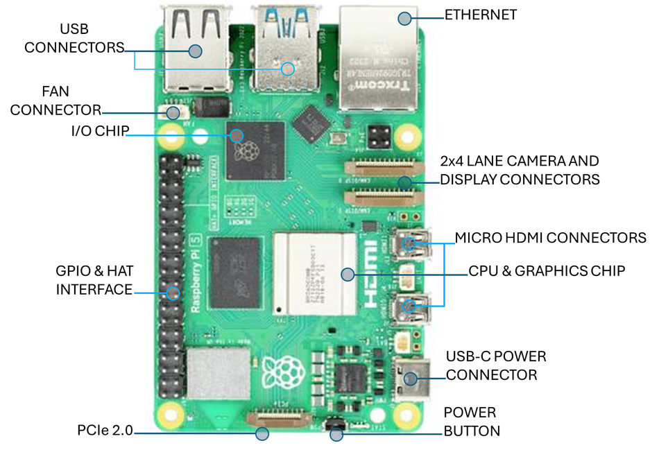
The Pi 5 is designed as a high‑performance SBC for professional and maker applications. Key features include:
Feature | Description | Relevance for GPIO users |
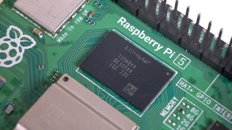
Processor & memory | Broadcom BCM2712 quad‑core 64‑bit Arm Cortex‑A76 CPU at 2.4 GHz with a 2 MB shared L3 cache and LPDDR4X‑4267 SDRAM options from 1 GB to 16 GB | Faster CPU enables complex real‑time processing of sensor data. |
Graphics & media | VideoCore VII GPU with OpenGL ES 3.1 and Vulkan 1.2 support; dual 4K p60 HDMI output | Allows simultaneous display while using the GPIO for control tasks. |
Storage & I/O | microSD slot supporting SDR104 mode; two USB 3.0 and two USB 2.0 ports; Gigabit Ethernet with PoE+ support; four‑lane MIPI camera/display transceivers; PCI Express 2.0 ×1 interface for NVMe; 40‑pin GPIO header | Enables high‑speed data transfer and additional expansion options. GPIO header remains central for custom peripherals. |
Power & clock management | 5 V/5 A DC input via USB‑C with power‑delivery support; integrated real‑time clock with external battery; dedicated power button | Stable power supply reduces noise on GPIO lines; RTC allows time‑stamping of data. |
These specifications position the Pi 5 as both a desktop replacement and an embedded controller. However, real hardware interfacing still relies on the 40‑pin header.
Pi 5 Pin Numbering and Layout
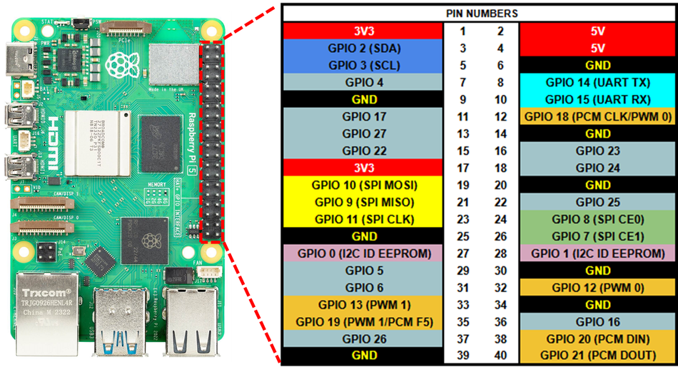
The Pi 5 has the same 40‑pin dual‑row header found on recent Raspberry Pi models. Pins are numbered sequentially from 1 in the top‑left corner (3.3 V power) to 40 in the bottom‑right.
Odd‑numbered pins occupy the left column, and even‑numbered pins the right column when the USB and Ethernet ports are facing away from you. It uses two numbering schemes:
Physical pin numbers (1–40): refer to the location on the connector.
Broadcom (BCM) GPIO numbers (0–27): correspond to the logical GPIO lines controlled by the RP1; these numbers may not match the physical pins.
When programming with libraries like gpiod, you often specify the BCM number and the gpiochip. Libraries such as gpiozero allow using physical pin numbers by specifying the pin_factory.
Pinout Tables
The following tables present the summary for Raspberry Pi 5’s 40‑pin header. Power and ground pins are fixed; the remaining pins show the RP1 GPIOs, which are capable of various alternate functions.
Power and Ground pins
Purpose | Voltage | Physical Pin(s) | Description |
Power Pins (3V3 and 5 V) | 3.3 V | 1, 17 | Provide voltage supply |
5 V | 2,4 | ||
Ground | 0 V | 6, 9, 14, 20, 25, 30, 34, 39 | Ground connection |
Suggested Reading: What is GND in a Circuit: The Complete Guide for Digital Design and Hardware Engineers
RP1 GPIO pins
Physical pin | BCM GPIO | Typical I/O purpose | Notes |
3 | 0 | I²C SDA (I²C0) | SDA line; alternate SPI 2 chip‑select |
5 | 1 | I²C SCL (I²C0) | SCL line; alternate SPI 2 SIO1 |
7 | 4 | GP Clock 0 / GPIO | Often used for 1‑wire devices; supports clock output |
8 | 8 | UART TXD0 | Serial transmit; also SPI 4 chip select |
10 | 9 | UART RXD0 | Serial receive; alternate SPI 4 SIO0 |
11 | 17 | GPIO17 | Can serve as PWM or general I/O |
12 | 18 | GPIO18 | Supports PWM channel and audio functions |
13 | 27 | GPIO27 | General I/O |
15 | 22 | GPIO22 | General I/O |
16 | 23 | GPIO23 | General I/O |
18 | 24 | GPIO24 | General I/O |
19 | 10 | SPI 0 MOSI | First SPI bus master out; can be repurposed |
21 | 9 | SPI 0 MISO | Master in; also I²C or general I/O |
22 | 25 | GPIO25 | General I/O |
23 | 11 | SPI 0 SCLK | SPI clock |
24 | 8 | SPI 0 CS0 | Chip‑select 0 |
26 | 7 | SPI 0 CS1 | Chip‑select 1 |
27 | – | ID_SD | I²C EEPROM data (HAT identification) |
28 | – | ID_SC | I²C EEPROM clock |
29 | 5 | GPIO5 | General I/O |
31 | 6 | GPIO6 | General I/O |
32 | 12 | GPIO12 | PWM channel; audio left |
33 | 13 | GPIO13 | PWM channel; audio right |
35 | 19 | GPIO19 | I²S word select or PWM |
36 | 16 | GPIO16 | General I/O |
37 | 26 | GPIO26 | General I/O |
38 | 20 | GPIO20 | General I/O / clock |
40 | 21 | GPIO21 | General I/O / clock |
Since the RP1 multiplexes many peripherals, several GPIOs can provide alternate functions such as additional UARTs, SPI buses or DPI signals. The list provided above shows the default assignments for the pins. When a pin is configured for an alternate function, its role changes accordingly.
Recommended Reading: Meet the new Raspberry Pi 5
RP1 Alternate Functions and Device‑Tree Overlays
The RP1 chip is a custom southbridge that offloads I/O from the BCM2712. It supplies 28 multi‑functional GPIOs on the 40‑pin header and each line can select from up to nine alternate functions. For example:
UARTs: Up to five serial ports are available. The first (UART0) defaults to pins 8 (TX) and 10 (RX). Additional ports (UART1–4) must be enabled via dtoverlay=uartX-pi5 with matching pin assignments.
SPI interfaces: Six SPI controllers support both master and slave modes. SPI 0 uses pins 19–26 by default; other SPI instances can be mapped to alternate pins via overlays.
I²C buses: Four I²C controllers allow connecting numerous sensors and EEPROMs. I²C0 is mapped to pins 3 and 5, but additional buses can be routed to other pins such as GPIO 10/11 or 12/13. Use overlays like dtoverlay=i2c1-pi5,pins_10_11 to reassign pins.
I²S audio: Two I²S interfaces provide stereo digital audio input and output. GPIO 18–21 carry clocks and data lines for the first I²S instance. Pair this with external codecs for hi‑fi audio systems.
PWM: The RP1 offers a four‑channel PWM generator and a separate AUDIO_OUT peripheral that uses GPIO 12/13 for stereo audio. PWM can be used for motor control, LED dimming or servo driving.
DPI (Display Parallel Interface): A 24‑bit DPI output uses GPIO0–27 to drive RGB LCD panels. This feature enables designers to integrate parallel displays without HDMI.
SDIO/eMMC: GPIO22–27 carry the SDIO interface for the on‑board microSD slot, but these lines can also be repurposed for general I/O when not in use.
Suggested Reading: Discontinuation of eMMC: A Guide for Developers and OEMs
To assign an alternate function, engineers edit /boot/config.txt and add the appropriate dtoverlay line. For example, enabling the second I²C bus on GPIO10 and GPIO11 uses dtoverlay=i2c1-pi5,pins_10_11.
Electrical Limits and Safety
GPIO pins are not indestructible. The RP1 GPIO bank (VDDIO0) can be powered at 1.8 V or 3.3 V, and when the RP1 is powered the pins are 5 V tolerant; however, when unpowered the absolute maximum voltage is 3.63 V. Exceeding these limits can damage the chip.
It is recommended to operate the Pi 5 in a ventilated environment, avoid contact with conductive surfaces and use stable power supplies. The GPIO usage white paper similarly emphasises ESD precautions and proper handling.
Programming the Raspberry Pi 5 GPIO
Modern APIs: libgpiod and Python bindings
The deprecation of the sysfs GPIO interface means engineers should adopt libgpiod for new designs. This C library abstracts gpiochips and lines across different boards. Python bindings are available through the gpiod module, while gpiozero offers an even higher‑level API.
The following example toggles a GPIO line using Python’s gpiod binding. It blinks an LED connected to physical pin 11 (BCM 17). First install the library (sudo apt install python3-libgpiod) and then run:
import gpiod
import time
chip = gpiod.Chip('gpiochip0')        # user‑facing GPIOs on Pi 5
led_line = chip.get_line(17)          # BCM GPIO number
config = gpiod.LineRequest()          # configuration object
config.consumer = 'blink'             # label for the consumer
config.request_type = gpiod.LINE_REQ_DIR_OUT
led_line.request(config)

try:
    while True:
        led_line.set_value(1)         # turn on LED
        time.sleep(0.5)
        led_line.set_value(0)         # turn off LED
        time.sleep(0.5)
except KeyboardInterrupt:
    led_line.set_value(0)
    led_line.release()
The script opens gpiochip0 (RP1), requests line 17 as an output and toggles it. Notice the use of BCM numbering. If you prefer physical pin numbers or want simplified classes like LED, the gpiozero library handles this internally.
Legacy APIs: RPi.GPIO and pigpio
Some existing code still uses the RPi.GPIO library. Although RPi.GPIO now supports the Pi 5 via libgpiod under the hood, you must update to the latest version. For backward compatibility you can write:
import RPi.GPIO as GPIO
import time
GPIO.setmode(GPIO.BCM)
GPIO.setup(17, GPIO.OUT)
try:
    while True:
        GPIO.output(17, GPIO.HIGH)
        time.sleep(0.5)
        GPIO.output(17, GPIO.LOW)
        time.sleep(0.5)
except KeyboardInterrupt:
    pass
finally:
    GPIO.cleanup()
However, direct register access libraries or older sysfs interfaces no longer work reliably on Pi 5 due to the RP1 architecture.
Practical Implementation Examples
Example 1: Reading a push button
To read a momentary push button, connect one side of the button to physical pin 13 (BCM 27) and the other side to ground. Use the built‑in pull‑up resistor so the input reads high when the button is not pressed. The following Python code uses gpiozero:
from gpiozero import Button
from signal import pause
button = Button(13, pull_up=True)  # physical pin numbering
def on_press():
    print("Button pressed!")
button.when_pressed = on_press
pause()  # wait indefinitely
When the button is pressed, the callback executes. This example demonstrates how gpiozero automatically selects gpiochip0 on Pi 5.
Example 2: Interfacing with an I²C temperature sensor
High‑level engineers often need to integrate sensors. Consider the popular BME280 temperature, humidity and pressure sensor. Connect its SCL line to physical pin 5 (BCM 1) and its SDA line to pin 3 (BCM 0). Power the sensor from the 3.3 V pin. Enable the I²C interface in raspi‑config or by adding dtparam=i2c_arm=on to /boot/config.txt. Install the smbus2 library and run:
import smbus2
import time
bus = smbus2.SMBus(1)  # I²C bus 1 corresponds to pins 3 and 5
BME280_I2C_ADDR = 0x76
# Read temperature register (simplified)
def read_temp():
    raw = bus.read_word_data(BME280_I2C_ADDR, 0xFA)  # temperature MSB
    temp = ((raw & 0xFF) << 8) | (raw >> 8)
    return temp / 100.0
while True:
    print(f"Temperature: {read_temp()} °C")
    time.sleep(1)
This code reads the temperature register periodically. For production use you should use a dedicated BME280 driver library that handles calibration values.
Example 3: SPI‑based ADC for analog measurements
Raspberry Pi boards lack analog inputs, but engineers can connect external ADCs such as the MCP3008 via SPI. Wire physical pins 19 (MOSI), 21 (MISO), 23 (SCLK) and 24 (CE0), and power the ADC from 3.3 V and ground. Using the spidev Python library:
import spidev
import time
spi = spidev.SpiDev()
spi.open(0, 0)          # bus 0, device 0 (CE0)
spi.max_speed_hz = 1_000_000
def read_channel(channel):
    # MCP3008 expects 3 bytes: start bit, config bits and a dummy byte
    cmd = [1, (8 + channel) << 4, 0]
    resp = spi.xfer2(cmd)
    value = ((resp[1] & 3) << 8) | resp[2]
    return value
while True:
    adc0 = read_channel(0)
    voltage = (adc0 / 1023) * 3.3
    print(f"ADC value: {adc0}, Voltage: {voltage:.2f} V")
    time.sleep(1)
This script continuously reads channel 0 of the ADC and converts the raw value to a voltage. Since the MCP3008 is a 10‑bit ADC, its full‑scale input is 3.3 V.
Example 4: Generating PWM for motor control
Controlling motors requires a PWM signal. The RP1 provides four hardware PWM channels. To drive a small DC motor through a transistor on GPIO12 (physical pin 32):
import gpiod
import time
chip = gpiod.Chip('gpiochip0')
pwm_line = chip.get_line(12)
config = gpiod.LineRequest()
config.consumer = 'pwm'
config.request_type = gpiod.LINE_REQ_DIR_OUT
pwm_line.request(config)
def set_duty_cycle(duty):
    period = 0.02  # 50 Hz period
    on_time = period * duty
    pwm_line.set_value(1)
    time.sleep(on_time)
    pwm_line.set_value(0)
    time.sleep(period - on_time)
try:
    while True:
        for duty in [0.0, 0.25, 0.5, 0.75, 1.0]:
            for _ in range(25):
                set_duty_cycle(duty)
            print(f"Duty cycle: {duty*100:.0f}%")
except KeyboardInterrupt:
    pwm_line.set_value(0)
    pwm_line.release()
Although software PWM is used here for simplicity, using the kernel’s hardware PWM driver (via /sys/class/pwm or the pigpio daemon) is recommended for precise control.
Advanced Use Cases and Considerations
Audio via I²S and PWM
The Pi 5’s audio subsystem offers both I²S (Inter‑IC Sound) and PWM‑based audio. GPIO 18–21 carry I²S signals, which can feed high‑fidelity DACs. GPIO 12/13 are reserved for stereo PWM audio output when the audio_pwm_mode=1 overlay is loaded.
Suggested Reading: What Is a PWM Signal? Fundamentals and Practical Applications for Engineers
Parallel displays with DPI
Driving parallel RGB displays directly from the Pi 5 is possible using the DPI interface. The 24‑bit DPI uses GPIO0–27 for pixel data, HSync, VSync and pixel clock. Because DPI consumes nearly all GPIOs, it is best suited to designs where few external peripherals are needed.
PCIe expansion via M.2
A noteworthy feature of the Raspberry Pi 5 is its single‑lane PCI Express 2.0 interface, through a fine‑pitch FPC connector. By attaching an official M.2 HAT+ you can add NVMe SSD storage, high‑speed network adapters or other PCIe peripherals. While not part of the GPIO header, this interface emphasizes the board’s versatility for embedded systems.
Suggested Reading: Add cellular connectivity to your Raspberry Pi
What’s Different from Raspberry Pi 4?
The physical header for Pi 5 hasn’t changed. But there are subtle differences and upgrades such as:
The GPIOs are controlled by the RP1 instead of the SoC’s GPIO block, introducing new alternate functions and requiring updated drivers.
Higher tolerance: When powered, RP1 GPIOs can withstand up to 5 V signals, whereas Pi 4 pins were not 5 V tolerant.
Reordered gpiochips: Kernel updates ensure gpiochip0 maps to user‑visible pins on Pi 5.
Firmware update requirement: UART overlays do not work on factory firmware; updating via rpi-update is necessary.
Conclusion
The Raspberry Pi 5 retains the familiar 40‑pin header while integrating the powerful RP1 southbridge to provide richer peripheral interfaces. Understanding the GPIO pinout—including physical and BCM numbering, electrical characteristics, and alternate functions—is essential for engineers building embedded systems.
By using modern software libraries and adhering to electrical safety guidelines, you can confidently design digital logic circuits, sensor networks and control systems around the Pi 5. As Raspberry Pi continues to evolve, stay up to date with firmware updates and documentation.
FAQs
1. What is the difference between physical pin numbers and BCM GPIO numbers on the Raspberry Pi 5?
Physical pin numbers refer to the position on the 40‑pin header (pins 1–40). BCM GPIO numbers correspond to logical pins managed by the RP1 chip. For example, physical pin 11 maps to BCM 17. Software libraries may require one or the other; always consult the documentation of your chosen library.
2. Are Raspberry Pi 5 GPIOs 5 V tolerant?
When the RP1 chip is powered, the GPIO bank can withstand 5 V signals. If the RP1 is unpowered (e.g., during power‑off or certain low‑power modes), do not exceed 3.63 V on any GPIO line.
3. How do I enable additional UARTs or I²C buses?
Use device‑tree overlays in /boot/config.txt. For example, dtoverlay=uart1-pi5 enables UART 1, and dtoverlay=i2c1-pi5,pins_10_11 routes I²C 1 to pins 10 and 11.
4. Which library should I use to control GPIOs on the Pi 5?
Prefer libgpiod (with Python bindings gpiod) or high‑level libraries like gpiozero. These libraries operate on gpiochips and remain compatible across Pi models.
5. Can I use old code written for RPi.GPIO on the Pi 5?
Yes, provided you update to the latest version of RPi.GPIO, which uses libgpiod internally. However, avoid direct register access or deprecated sysfs interfaces; these methods are incompatible with the RP1 architecture.
6. How many pins are reserved for HAT identification?
Physical pins 27 and 28 are reserved for the I²C ID EEPROM used by HATs (ID_SD and ID_SC). They should not be repurposed unless you are certain no HAT identification is required.
7. What are the best practices for protecting GPIOs from damage?
Use series resistors and level shifters when interfacing with higher‑voltage devices. Avoid hot‑plugging circuits while the Pi is powered. Always handle the board with anti‑static precautions and operate it in a dry, well‑ventilated environment.
References
Raspberry Pi Ltd, "Raspberry Pi 5 product brief," Jan. 2025. [Online]. Available: https://datasheets.raspberrypi.com/rpi5/raspberry-pi-5-product-brief.pdf
"GPIO usage on Raspberry Pi devices," Raspberry Pi Ltd, white paper RP-006553-WP. [Online]. Available: https://pip.raspberrypi.com/categories/685-whitepapers-app-notes/documents/RP-006553-WP/A-history-of-GPIO-usage-on-Raspberry-Pi-devices-and-current-best-practices.pdf
"Raspberry Pi 5 GPIO pinout," pinout.ai. [Online]. Available: https://pinout.ai/raspberry-pi-5
"RPI5.pinout," GitHub. [Online]. Available: https://raw.githubusercontent.com/Felipegalind0/RPI5.pinout/main/README.md
"Raspberry Pi overlay documentation," GitHub. [Online]. Available: https://github.com/raspberrypi/firmware/blob/master/boot/overlays/README
in this article
1. Key Takeaways2. Introduction3. What Is a GPIO?4. Raspberry Pi 5 Hardware Overview5. Pi 5 Pin Numbering and Layout6. RP1 Alternate Functions and Device‑Tree Overlays7. Programming the Raspberry Pi 5 GPIO8. Practical Implementation Examples9. Advanced Use Cases and Considerations10. Conclusion11. FAQs12. References