Raspberry Pi 3 Pinout: A Comprehensive Technical Guide for Engineers
A practical guide for engineers and students to master the Raspberry Pi 3 pinout, covering GPIO concepts, annotated tables, code examples, and real-world projects for building reliable circuits and custom hardware.

17 Dec, 2025. 14 minutes read
Key Takeaways
Raspberry Pi 3 Pinout: The Raspberry Pi 3’s 40‑pin header offers 28 GPIO pins plus power, ground, and reserved pins. The header layout remains consistent across the Pi 3 Model B and Model B+ and is shared with newer boards like the Pi 4.
Power and Ground Distribution: Two 5V pins and two 3.3V pins provide regulated power, while eight pins are connected to ground. All GPIO pins operate at 3.3 V and are not 5V tolerant [6].
Multiple communication protocols are supported: Dedicated pins implement I²C, SPI, UART, PWM, and PCM/I²S interfaces. Understanding these protocols enables you to connect sensors, displays, and audio devices.
Numbering schemes differ: Pins can be identified by their physical position, Broadcom (GPIO) number, or WiringPi number. Choosing the correct scheme is essential when programming in Python or C.
Practical implementations using Python libraries simplify hardware control: Examples using RPi.GPIO and gpiozero illustrate how to toggle outputs, read switches, and generate PWM signals. Engineers can quickly prototype and test circuits on the Pi 3.
Introduction
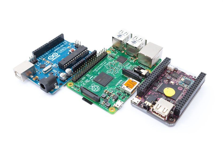
In the world of electronics prototyping, hobbyists and engineers have a wide range of tools at their disposal. Platforms like Arduino have long been popular for building simple circuits and learning embedded systems, while microcontrollers from various vendors offer specialized functionality.
The Raspberry Pi platform revolutionised computing for both hobbyists and professionals by providing a powerful Linux‑capable computer in a credit‑card‑sized board. With integrated Wi‑Fi, Bluetooth, and robust graphics, the Raspberry Pi 3 Model B and Model B+ remain popular for embedded prototyping, IoT devices, and even small‑scale industrial control. Its versatility makes it suitable for everything from learning GPIO control to building sophisticated embedded systems. Understanding the Raspberry Pi 3 pinout is essential for anyone working with this versatile board.
This article explains the Raspberry Pi 3 pinout and how its 40‑pin header connects GPIO, power, and ground pins for building circuits. It covers key features like power distribution, communication protocols, and pin numbering, and shows how Python libraries make prototyping and testing hardware easy for beginners and professionals alike.
Raspberry Pi 3: Hardware Overview
What Is the Raspberry Pi 3?
The Raspberry Pi 3 is a single-board computer designed for education, prototyping, and embedded system development. The Pi 3 combines processing, memory, networking, and storage on one board while exposing hardware interfaces through a GPIO pinout like the Raspberry Pi Zero and Zero W.
Unlike traditional microcontroller-based platforms like Raspberry Pi Pico, which target real-time control, it runs a full Linux operating system while maintaining a small form factor and low power consumption. This allows it to support high-level programming, networking, and multimedia applications alongside direct hardware interfacing through its GPIO header. Newer platforms such as the Raspberry Pi 5 offer higher performance, but retain the same expansion philosophy.
Raspberry Pi 3 Model B and Model B+
The Raspberry Pi 3 family includes two closely related variants: the Model B and the Model B+. Both boards are based on the Broadcom BCM2837 system-on-chip and include 1 GB of RAM, ensuring software compatibility across the platform [6].
The Model B+ introduces several improvements over the original Model B. These include a higher CPU clock speed of 1.4 GHz compared to 1.2 GHz, improved Ethernet throughput, and support for dual-band 802.11ac Wi-Fi. Despite these enhancements, both models retain the same expansion capabilities and peripheral interfaces.
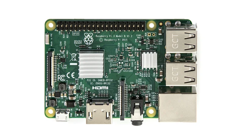
Both boards provide four USB 2.0 ports, a full-size HDMI output, CSI camera and DSI display connectors, a combined audio and composite video output via a 3.5 mm jack, and a microSD card slot for storage. Both models expose a 40-pin general-purpose input/output header used for hardware expansion.
Numbering Schemes
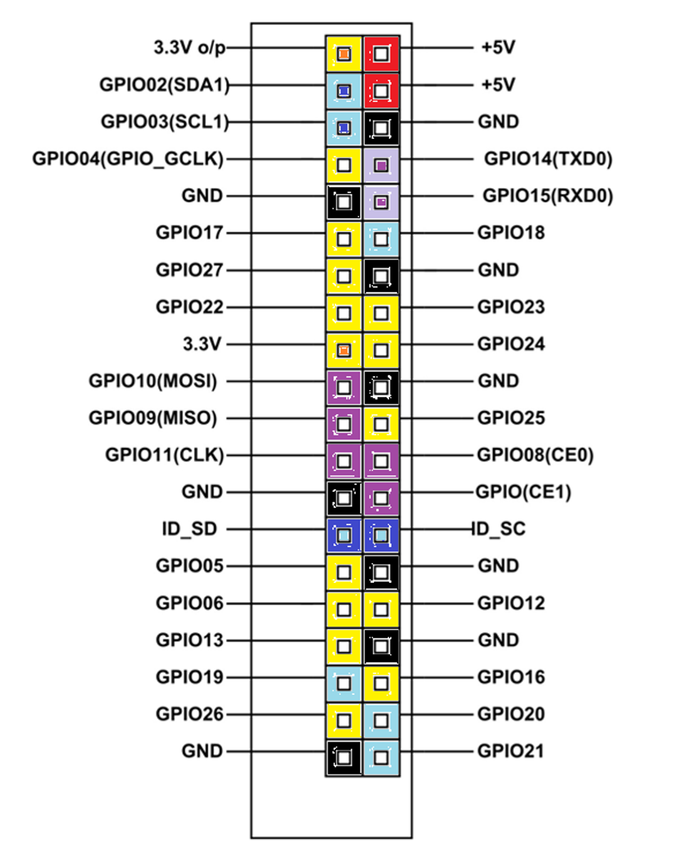
The Raspberry Pi GPIO header supports multiple pin numbering schemes:
Physical (board) numbering counts pins sequentially from 1 – 40 based on their position on the header. Pin 1 is in the top‑left corner when the Pi is oriented with the HDMI port on the left and the GPIO header on the right.
Broadcom (BCM) or GPIO numbering uses the SoC’s GPIO names (e.g., GPIO 17). This scheme is used in many Python libraries, such as RPi.GPIO and gpiozero [5].
WiringPi numbering is an abstraction used by the WiringPi library and Pi4J. The Pi4J documentation notes that its default numbering scheme mirrors WiringPi and can be configured to use BCM numbering if desired [2].
When programming GPIO, the selected numbering scheme must match the pin references used in code. Using the wrong scheme can result in incorrect pin access and unintended hardware behavior.
Raspberry Pi 3 Pinout: Detailed Breakdown
The Raspberry Pi 3 exposes a 40-pin GPIO header that provides access to power, ground, general-purpose I/O, and multiple communication interfaces. Understanding the role of each pin type is essential for designing reliable and safe hardware interfaces.
GPIO Header Layout and Orientation
The header pins are arranged in two rows of 20 pins. Even-numbered pins form the outer row, while odd-numbered pins form the inner row. When the board is oriented with the HDMI connector on the left and the USB ports on the right, pins 1 and 2 are located in the top-left corner of the header.
The 40-pin header is backward-compatible with earlier Raspberry Pi models that used a 26-pin header. Newer boards extend the original layout by adding additional pins while preserving the original pin positions, ensuring compatibility with older expansion boards.
Operating Voltage and Logic Levels
Although the Raspberry Pi 3 is powered from a 5V supply, the system-on-chip and GPIO logic operate at 3.3V [3]. As a result, all GPIO pins are 3.3V-tolerant, and applying higher voltages directly to these pins can permanently damage the board [6].
The GPIO header provides regulated 5V and 3.3V power rails intended for low-power peripherals. These rails draw from the main power supply and have limited current capacity. High-current devices should be powered using external regulators or dedicated power supplies to avoid voltage drops and system instability [3].
Recommended Reading: Raspberry Pi 4 Pinout: A Comprehensive Guide for Engineers
Power and Ground Pins
Out of the 40 pins on the Raspberry Pi 3 GPIO header, four are dedicated power pins, eight are ground (GND) pins, and two are reserved for the HAT ID EEPROM. The power pins consist of two 5 V pins (physical pins 2 and 4) and two 3.3V pins (physical pins 1 and 17) [3]. The eight ground pins(6, 9, 14, 20, 25, 30, 34, 39) are distributed along the header to provide low-impedance return paths. When designing circuits, using multiple ground connections helps reduce noise and improve signal integrity, and high current should not be drawn through a single ground pin.
The 5V power pins are commonly used by HATs and expansion boards, but they are not current-limited independently of the main supply. Designers must consider the total system load, especially when combining external devices with USB peripherals and the SD card, to avoid undervoltage conditions.
| Function | Pin Number | Notes |
| 3.3 V Power | 1, 17 | Limited current |
| 5V Power | 2, 4 | Directly from the main power |
| Ground (GND) | 6, 9, 14, 20, 25, 30, 34, 39 | Low-impedance return paths |
| Reserved (ID EEPROM) | 27 (SDA), 28 (SCL) | For HAT identification |
Reserved ID EEPROM Pins
Pin 27 (GPIO 0) and 28 (GPIO 1) are reserved for the I²C interface used by the ID EEPROM found on Raspberry Pi HATs. This EEPROM stores board identification data that allows the operating system to automatically load the correct device tree overlay.
These pins should not be used for general-purpose I/O unless an appropriate EEPROM is present. When no HAT is attached, they should be left unconnected to avoid conflicts.
General-Purpose I/O And Digital Signaling (26 GPIO Pins)
Most pins labeled GPIO on the Raspberry Pi 3 can be configured in software as either digital inputs or digital outputs. When configured as inputs, GPIO pins can detect logic levels up to 3.3 V [3]. Each input pin can optionally enable an internal pull-up or pull-down resistor through software, which helps define a stable default state when no external signal is present. This is particularly useful when interfacing with mechanical switches, buttons, or open-collector/open-drain outputs from sensors.
When configured as outputs, GPIO pins can drive logic-level signals at 3.3 V. Each pin can source or sink a limited amount of current—typically up to approximately 16 mA per pin—with a recommended maximum combined current of about 50 mA across all GPIO pins. These limits make the GPIO suitable for driving LEDs (with appropriate current-limiting resistors), opto-isolator inputs, and logic inputs on other digital devices.
Because of these current and voltage limitations, GPIO pins should not be used to directly power motors, relays, solenoids, or other high-current or inductive loads. Doing so can damage the GPIO circuitry or cause system instability. For such applications, external driver circuits—such as bipolar transistors, MOSFETs, relay driver modules, or dedicated driver ICs—should be used. These components allow the GPIO pins to control higher-power devices safely while protecting the Raspberry Pi.
In addition to simple digital input and output, many GPIO pins support alternate functions, such as hardware PWM, SPI, I²C, UART, and PCM/I²S. Enabling these alternate functions repurposes the pin from general-purpose use to a specific peripheral role, which must be considered when designing hardware or assigning pins in software.
| BCM GPIO | Physical Pin | Function/Alternate |
| 2 | 3 | I²C SDA1 |
| 3 | 5 | I²C SCL1 |
| 4 | 7 | GPIO 4 |
| 14 | 8 | UART TXD0 |
| 15 | 10 | UART RXD0 |
| 17 | 11 | GPIO 17 |
| 18 | 12 | GPIO 18 / PWM0 |
| 27 | 13 | GPIO 27 |
| 22 | 15 | GPIO 22 |
| 23 | 16 | GPIO 23 |
| 24 | 18 | GPIO 24 |
| 10 | 19 | SPI MOSI |
| 9 | 21 | SPI MISO |
| 25 | 22 | GPIO 25 |
| 11 | 23 | SPI SCLK |
| 8 | 24 | SPI CE0 |
| 7 | 26 | SPI CE1 |
| 5 | 29 | GPIO 5 |
| 6 | 31 | GPIO 6 |
| 12 | 32 | PWM0 |
| 13 | 33 | PWM1 |
| 19 | 35 | PCM FS / PWM |
| 16 | 36 | GPIO 16 |
| 26 | 37 | GPIO 26 |
| 20 | 38 | PCM DIN |
| 21 | 40 | PCM DOUT |
Communication interfaces
I2C Circuit bus
I²C (Inter-Integrated Circuit) is a synchronous, multi-master, multi-slave, two‑wire protocol originally developed by Philips Semiconductors. It allows a master (the Pi) to communicate with one or many slaves (sensors, displays, or microcontrollers) over a shared bus.
The Pi 3’s primary I²C bus (I²C‑1) appears on GPIO 2 (physical 3) for SDA and GPIO 3 (physical 5) for SCL. These pins already include pull‑up resistors on most Pi boards, so additional resistors are unnecessary for short cables. To use I²C:
Enable the interface via the Raspberry Pi Configuration tool (raspi-config → Interfacing Options → I2C → Enable).
Install the python3-smbus library if, not installed.
Use an I²C library (e.g., smbus2) to communicate with devices by their 7‑bit addresses.
When connecting multiple devices, ensure the combined bus capacitance and pull-up resistance meet I²C specifications. Longer cables may require stronger pull-ups or slower clock speeds.
Serial Peripheral Interface (SPI)
SPI is a synchronous full‑duplex protocol that uses separate lines for data and clock. The Random Nerd Tutorials guide describes SPI as allowing multiple peripherals to share a bus as long as each uses a different chip‑select line. The Raspberry Pi implements SPI on GPIO 10 (MOSI), GPIO 9 (MISO), GPIO 11 (SCLK), and two chip‑select pins, GPIO 8 (CE0) and GPIO 7 (CE1). Many devices (ADC chips, displays, flash memory) use SPI because it supports high data rates.
Like I²C, SPI is disabled by default. Enable it via raspi-config or by adding dtoverlay=spi0-1cs or spi0-2cs to /boot/config.txt. To interface with an MCP3008 analog‑to‑digital converter using Python’s spidev library:
import spidev
spi = spidev.SpiDev()
spi.open(0, 0)       # open bus 0, chip‑select 0
spi.max_speed_hz = 1_000_000

def read_channel(channel):
    cmd = [1, (8 + channel) << 4, 0]
    adc = spi.xfer2(cmd)
    result = ((adc[1] & 3) << 8) | adc[2]
    return result


value = read_channel(0)
voltage = value * 3.3 / 1023
This code reads the analog voltage on channel 0 of the MCP3008.
Note: The Raspberry Pi 3 has no built-in ADC; external converters are required for analog inputs.
UART Serial Communication
The Universal Asynchronous Receiver/Transmitter (UART) interface allows serial communication at adjustable bit rates. The Pi’s primary UART uses GPIO 14 (TXD) and GPIO 15 (RXD).
On the Pi 3, the hardware UART /dev/ttyAMA0 is connected to the Bluetooth module by default, and a miniUART /dev/ttyS0 is mapped to the GPIO header
This miniUART lacks parity support and may be unstable at high speeds. The miniUART has no parity support and may be unstable at high speeds. For reliable serial communication, such as with a microcontroller, disable Bluetooth and reassign the hardware UART using a device tree overlay [2].
To enable the serial console for debugging, add enable_uart=1 to /boot/config.txt or use raspi-config. Use picocom or screen on the host PC to open a terminal. When connecting 5 V UART devices, use a level shifter to avoid damaging the Pi.
Pulse Width Modulation (PWM)
PWM allows a digital pin to emulate an analog output by toggling between high and low at a fast frequency. The Random Nerd Tutorials PWM guide explains that PWM can control LED brightness and servo motor position by altering the duty cycle—the fraction of time the signal is high. A duty cycle of 50 % yields half brightness; 0 % is fully off, and 100 % is fully ON [4].
The Raspberry Pi has four hardware PWM pins: GPIO 12, GPIO 13, GPIO 18, and GPIO 19. Hardware PWM is more precise and CPU‑efficient than software PWM. However, if these pins are occupied by SPI or PCM functions, you can generate PWM signals on other pins using software libraries like RPi.GPIO or gpiozero. For example, to dim an LED on GPIO 18 using the gpiozero library:
from gpiozero import PWMLED
from time import sleep
led = PWMLED(18)  # BCM numbering

while True:
    for duty in [0.0, 0.25, 0.5, 0.75, 1.0]:
        led.value = duty
        sleep(1)
This script gradually changes the LED brightness by setting the PWM duty cycle. The gpiozero library handles the low‑level timing itself.
PCM/I²S for Digital Audio
The Raspberry Pi exposes a pulse‑code modulation (PCM) interface, also known as I²S (Inter‑IC Sound), for digital audio. The pins are GPIO 18 (CLK), GPIO 19 (FS), GPIO 20 (DIN), and GPIO 21 (DOUT). When configured in alternate function mode, these pins output a serial audio stream suitable for DACs or MEMS microphones. Enable I²S audio by loading an appropriate overlay, e.g., dtoverlay=hifiberry-dac, in /boot/config.txt.
Alternate Functions and Pin Multiplexing
The Broadcom BCM2837 SoC uses pin multiplexing to assign different functions (ALT0–ALT5) to each GPIO pin. This allows a single physical pin to support multiple peripheral functions depending on configuration. For example, GPIO 18 can act as a general‑purpose pin, PWM output, or PCM clock depending on the selected alternate function.
Engineers designing hardware must consult the BCM2837 datasheet for the full list of alternate functions and ensure there are no conflicts when enabling multiple peripherals.
Practical Implementations
Enabling Interfaces in Raspberry Pi OS
Many interfaces are disabled by default to reduce boot times and power consumption. Enable them via the graphical Raspberry Pi Configuration tool or the raspi-config terminal utility:
Run sudo raspi-config.
Select Interface Options.
Enable I2C, SPI, Serial Port, or One‑Wire as needed.
Reboot the system to apply changes.
Alternatively, you can add lines to /boot/config.txt such as dtparam=i2c_arm=on, dtparam=spi=on or dtoverlay=w1-gpio,gpiopin=4 to enable the interfaces at boot.
Reading a Digital Sensor via I²C
Consider interfacing a BME280 environmental sensor. The BME280 communicates over I²C at address 0x76 or 0x77. After enabling I²C and wiring the sensor’s SDA and SCL lines to pins 3 and 5, respectively, install the smbus2 and bme280 libraries. Then:
import bme280
import smbus2

port = 1
address = 0x76
bus = smbus2.SMBus(port)
bme280.load_calibration_params(bus, address)
data = bme280.sample(bus, address)
print(f"Temperature: {data.temperature:.2f} °C")
print(f"Pressure: {data.pressure:.2f} hPa")
print(f"Humidity: {data.humidity:.2f} %RH")
This program reads temperature, pressure, and humidity data and prints the results. The I²C bus allows multiple sensors to be chained together if their addresses do not collide.
Driving a Servo Motor using PWM
Servo motors require a control signal consisting of pulses at 50 Hz with variable width (e.g., 1–2 ms). Connect the servo’s signal wire to GPIO 12 or GPIO 13 (hardware PWM) [4]. The gpiozero library simplifies servo control:
from gpiozero import Servo
from time import sleep

servo = Servo(13)  # BCM numbering


while True:
    servo.min()  # 0 ms pulse (~0°)
    sleep(1)
    servo.mid()  # 1.5 ms pulse (~90°)
    sleep(1)
    servo.max()  # 2 ms pulse (~180°)
    sleep(1)
Using hardware PWM provides more stable timing and reduced jitter compared to software PWM. Because servo motors draw significant current, they should be powered from an external 5 V supply, with a common ground shared with the Raspberry Pi.
Streaming Digital Audio via I²S
For high-quality digital audio output, the Raspberry Pi 3 can be paired with a DAC HAT using the I²S/PCM interface. Devices such as the HiFiBerry DAC+ connect to GPIO 18–21 and require the appropriate device tree overlay.
Add <code><strong>dtoverlay=hifiberry-dac</strong></code> to <code><strong>/boot/config.txt</strong></code> and reboot the system. Audio playback can then be handled using ALSA or PulseAudio. Because the PCM pins share alternate functions with PWM, enabling an I²S DAC disables hardware PWM on those pins.
Design Considerations for Hardware Engineers
Creating custom HATs and Expansion Boards
When designing a custom expansion board (HAT), follow the Raspberry Pi HAT specification, which includes:
Mechanical alignment: Use a standard 2×20 female header with correct pin spacing and ensure that components clear the Pi’s USB, Ethernet, and HDMI connectors.
EEPROM implementation: Include a 32‑kbit I²C EEPROM on pins 27 and 28 to store your HAT’s vendor ID, product ID, and device tree overlay. This allows the OS to automatically configure GPIO functions and load drivers.
Power budgeting: Avoid exceeding the Pi’s 3.3 V regulator capacity. Provide your own power regulators for high‑current peripherals such as motors or LED strips.
ESD and level shifting: Protect GPIO pins with ESD diodes and buffer high‑voltage signals through level shifters or transistor stages. Remember that the pins are not 5 V‑tolerant.
Signal Integrity and Noise
High‑speed interfaces like SPI and I²S can be susceptible to noise, especially when cables are long. Keep traces short on custom PCBs, add ground planes, and route differential or clock signals carefully. Use proper decoupling capacitors near devices powered from the 5 V or 3.3 V rails to reduce voltage ripple.
Thermal Considerations
Although the Pi 3 is designed for casual hobby use, industrial deployments may subject it to higher ambient temperatures. Use heat sinks or forced airflow to cool the SoC when running CPU‑intensive tasks. Avoid placing heat‑sensitive components near the SoC on your expansion board.
Software Drivers and Device Tree Overlays
Whenever you enable a peripheral, the Linux kernel uses device tree overlays to configure GPIO multiplexing and load drivers. As a hardware designer, provide overlay files (.dtbo) for your HAT so that pin functions are set correctly. This ensures that pins are not left floating or driven inadvertently.
Conclusion
The Raspberry Pi 3 pinout might appear daunting at first, but understanding its structure unlocks a world of possibilities. With 28 general‑purpose pins, dedicated power and ground rails, and support for multiple communication protocols, the Pi 3 can interface with a wide range of sensors and actuators. It is essential to observe key safety rules: all GPIO pins operate at 3.3 V, and the ID EEPROM pins should remain unused unless an EEPROM is present. By learning the numbering schemes, planning pin usage, and leveraging Python libraries, engineers and students can prototype complex digital systems quickly and reliably.
Although the Raspberry Pi community continues to evolve with newer boards like the Pi 4 and Pi 5, the 40‑pin header remains consistent. This consistency protects investments in HATs and expansion boards and ensures that the knowledge gained here will remain relevant. While newer boards such as the Raspberry Pi 5 deliver significant performance improvements, and platforms like the Raspberry Pi Pico address real-time control use cases, the Raspberry Pi 3 remains a widely used and well-supported platform. Its stable GPIO pinout, reliable 5 V power distribution, and SD-card-based storage make it an excellent foundation for learning, prototyping, and long-term embedded designs.
Frequently Asked Questions (FAQ)
1. What are the differences between the Raspberry Pi 3 Model B and Model B+?
The Model B+ improves on the Model B by using a 1.4 GHz BCM2837B0 processor, dual-band 802.11ac Wi-Fi, faster Ethernet with optional Power over Ethernet (PoE) support, and improved power management. Both boards provide a 40-pin GPIO header and 1 GB of RAM.
2. Are the Raspberry Pi 3 and Raspberry Pi 4 pinouts identical?
Yes. The Pi 3 and Pi 4 share the same 40‑pin header layout, so most HATs and expansion boards are cross‑compatible. However, some alternate functions may differ due to changes in the SoC.
3. How many general-purpose input/output pins are available?
Out of the 40 header pins, 4 are power pins, 8 are ground pins, and 2 are reserved for the ID EEPROM, leaving 26 usable GPIO pins. Several of these GPIO pins are shared with alternate functions such as SPI, I²C, UART, PWM, or PCM when those interfaces are enabled.
4. Do Raspberry Pi GPIO pins support 5V logic?
No. Raspberry Pi GPIO pins operate at 3.3V logic levels. Applying 5V directly to a GPIO pin can permanently damage the board. Use level-shifting circuits when interfacing with 5V devices.
5. Which pins are reserved for the HAT ID EEPROM?
Pins 27 and 28 (BCM GPIO 0 and GPIO 1) are reserved for the I²C ID EEPROM used to identify HATs and load the appropriate device tree overlays. These pins should not be used for general-purpose functions unless designing a compliant HAT.
6. How do I enable SPI or I²C on the Raspberry Pi?
Use the <code>raspi-config</code> tool under Interface Options to enable SPI or I²C. Alternatively, add <code>dtparam=i2c_arm=on</code> or <code>dtparam=spi=on</code> to <code>/boot/config.txt</code> and reboot the system.
7. Can the Raspberry Pi read analog sensors?
The Raspberry Pi does not include an on-board analog-to-digital converter (ADC). To read analog signals, an external ADC—such as the MCP3008—must be connected, typically using the SPI interface.
References
[1] SparkFun Electronics, “Raspberry Pi GPIO: Pinout and Functionality,” SparkFun Learning Resources. [Online]. Available: https://learn.sparkfun.com
Accessed: 2025.
[2] Pi4J Project, “Pin Numbering – Raspberry Pi 3 Model B,” Pi4J Documentation. [Online]. Available: https://pi4j.com
Accessed: 2025.
[3] Random Nerd Tutorials, “Raspberry Pi Pinout Guide,” Random Nerd Tutorials. [Online]. Available: https://randomnerdtutorials.com
Accessed: 2025.
[4] Random Nerd Tutorials, “Raspberry Pi PWM Outputs,” Random Nerd Tutorials. [Online]. Available: https://randomnerdtutorials.com
Accessed: 2025.
[5] ElectronicWings, “Raspberry Pi GPIO Access,” ElectronicWings Documentation. [Online]. Available: https://electronicwings.com
Accessed: 2025.
[6] Pololu, “Raspberry Pi 3 Model B+ Product Overview,” Pololu Robotics & Electronics. [Online]. Available: https://pololu.com
Accessed: 2025.
in this article
1. Introduction2. Raspberry Pi 3: Hardware Overview3. Raspberry Pi 3 Pinout: Detailed Breakdown4. Communication interfaces5. Alternate Functions and Pin Multiplexing6. Practical Implementations7. Design Considerations for Hardware Engineers8. Conclusion9. Frequently Asked Questions (FAQ)10. References