USB-C Pinout In Depth: A Comprehensive Technical Guide for Engineers
An insight into one of the most futuristic designs for power, data transfer, and communication. Find out the essentials of USB-C type pinout, its use cases, architecture, and implementation in modern computing devices

14 Jul, 2025. 16 minutes read
Key Takeaways
The symmetrical 24-pin design of USB-C allows for a reversible plug, ensuring no functional loss regardless of orientation. Its pins are dedicated to power, ground, high-speed data (SuperSpeed and USB 2.0), sideband communication, and configuration.
Dynamic role and power negotiation are managed by the CC pins, enabling flexible power delivery up to 240W with USB PD 3.1; correct resistor termination on these pins is crucial for proper power negotiation.
High-speed data lanes, consisting of four SuperSpeed pins, support up to 10 Gbps per lane for technologies like USB4 and can be repurposed for other protocols such as PCIe or DisplayPort through Alternate Mode.
For design and integration, robust USB-C implementations require approved controllers, E-Marker chips for high-current cables, ESD protection, and careful PCB routing, with strict adherence to USB-IF specifications to prevent failures.
The USB-C ecosystem is supported by comprehensive standards and a certification process, with ongoing updates like USB4 Version 2.0 pushing for even higher speeds and power delivery, solidifying its role as a versatile, future-proof connector.
Introduction
USB-C, or USB Type-C, has rapidly emerged as the ubiquitous connector standard, fundamentally reshaping how we connect and power our electronic devices. More than just a reversible plug, its sophisticated 24-pin architecture and intelligent communication protocols enable a remarkable convergence of power delivery, high-speed data transfer, and versatile alternate modes for video and other functionalities.
This article discusses the intricate pinout of USB-C. We will explore:
Why its design is critical for modern computing
Underlying architecture
Different variants and associated protocols
Diverse applications and compelling use cases across consumer and industrial electronics.
Foundational Principles & Terminology
USB Type-C is a reversible connector that consolidates data, video, and power on a single cable. Unlike prior Type-A/B USB connectors that had distinct host and device ends, USB-C’s symmetrical design allows either end of a cable to plug into a host or device port.
Downstream Facing Port (DFP) refers to a host or power source port
Upstream Facing Port (UFP) refers to a device or sink port.
USB-C ports can be dual-role (DRP), dynamically swapping host/device roles and source/sink power roles as negotiated. This flexibility is achieved through the Configuration Channel (CC) pins and the USB Power Delivery protocol.
USB-C Pin Groups
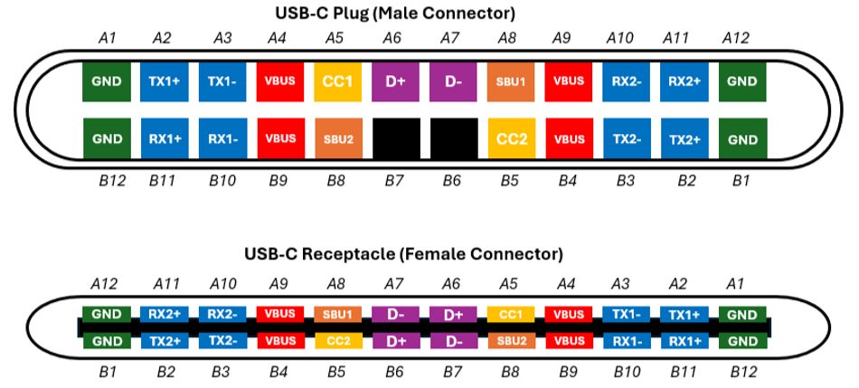
The USB-C connector integrates several functional pin groups for broad capability. The following table summarizes the pin groups:
Pin Group | Number of Pins (in receptacle) | Function / Purpose | Key Details |
Power (VBUS & Ground) | 8 (4 VBUS, 4 Ground) | Provide bus power and ground return. | Multiple pins for lower resistance and higher current capacity. |
High-Speed Data (TX/RX) | 8 (4 TX, 4 RX) | Support "SuperSpeed" data for USB 3.2 Gen1/Gen2, USB4, and Alternate Modes. | Four shielded differential pairs (two transmit, two receive), duplicated on both sides for reversible plug orientation; ensures two TX and two RX lines are always accessible. |
USB 2.0 Data (D+/D-) | 4 (2 D+, 2 D-) | Carry legacy USB 2.0 signals (up to 480 Mbps). | One pair on each side (A6/B6 D+ and A7/B7 D- are internally connected) effectively creates a single USB 2.0 channel. |
Sideband Use (SBU) | 2 (SBU1, SBU2) | Used for auxiliary signals in Alternate Modes (e.g., DisplayPort AUX channel) or analog audio in specific accessory modes. | Low-frequency pins. |
Configuration Channel (CC) | 2 (CC1, CC2) | Manage cable orientation detection, mode configuration, and USB Power Delivery (PD) communication. | Use BMC encoding (~300 kHz) for PD. In a plug, one CC pin becomes VCONN to power active cable electronics (e-marker chips, re-timers). |
Reversible Orientation & CC Logic
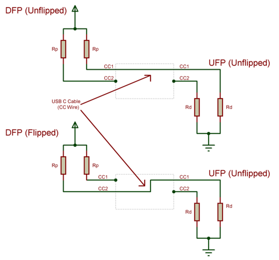
When a USB-C plug is inserted, only one of the two CC pins will mate between plug and receptacle (CC1 if “right-side up” vs CC2 if flipped). The port’s CC logic detects which CC pin is connected to establish cable orientation. Through a simple analog protocol, resistors on CC pins also indicate the roles: a source (DFP) applies a pull-up resistor Rp to 5 V on its CC pins, while a sink (UFP) applies a pull-down resistor Rd (~5.1 kΩ to ground) on its CC pins.
Upon connection, the source senses a voltage divider on the active CC line and, based on the voltage, detects the sink’s presence and whether the cable is electronically marked. This voltage divider further encodes the source’s current capability: standard USB default (500 mA for USB 2.0, 900 mA for USB 3.x) is signaled by 56 kΩ Rp, medium (1.5 A) by 22 kΩ, and high (3 A) by 10 kΩ. The sink (device) monitors CC to determine how much current it may draw and will only draw up to that limit, ensuring safe power negotiation.
Key Terms to Remember
It’s important to distinguish the connector from protocols.
USB-C refers to the connector form factor and pinout, not a specific data protocol. The same USB-C port could carry USB 2.0 or USB4, or even non-USB protocols in Alternate Mode (e.g., DisplayPort or Thunderbolt).
USB Power Delivery (PD) is an optional higher-level negotiation layered on CC pin communication that allows dynamic voltage/current contracts beyond the 5 V default.
E-marker - (Electronically Marked) cables contain a chip (powered via VCONN) that communicates cable capabilities (e.g., supporting 5 A current or 20 Gbps SuperSpeed).
Alt Mode - refers to repurposing the USB-C SuperSpeed/SBU pins for alternate data protocols.
Architecture & Variants
USB-C’s pinout implementation can vary slightly between receptacles, plugs, and cables, each of which has unique wiring rules while maintaining interoperability.
A USB-C receptacle (female port), as found on host and device hardware, exposes all 24 pins in a standardized arrangement.
A USB-C plug (male connector), such as the end of a cable or a captive device cable, also has 24 physical pins but is wired differently internally.
Notably, a plug has only one set of USB 2.0 D± wires (instead of two): the A6 and B6 pins (D+) are tied together in the plug, as are A7 and B7 (D−). This means the cable itself carries only one D+ and one D− conductor through the dual D± pins on a receptacle converge into single pairs in the cable.
Additionally, on a plug, one of the two CC pins is not connected to the cable’s CC wire; instead, it is reassigned as VCONN (on B5) to provide power to any active circuitry in the cable. The other CC pin (A5 in the plug) is the one that passes through as the cable’s single CC conductor. Thus, a cable only has one usable CC line running end-to-end (plus one VCONN line if needed for cable electronics). This architecture is why USB-C plug wiring must differ slightly from receptacle wiring.
Cable Wiring
A full-featured USB-C cable has 18 conductors despite 24-pin connectors on each end. It carries: 4 power (all VBUS pins tied together), 4 ground (all GND tied), 1 pair D±, 4 SuperSpeed pairs (TX/RX ×2), 1 CC line, 2 SBUs, and 1 VCONN (if an electronically marked cable).
Simpler USB-C cables (e.g. USB 2.0-only charging cables) omit the SuperSpeed pairs and SBU lines to save cost; these will still carry power and USB 2.0 data, but cannot support fast USB 3.x data or Alt Modes.
Receptacle vs Plug Design
Most devices will use a USB-C receptacle on their PCB. However, some embedded applications use a USB-C plug directly (for example, a dongle or cable-attached device where the connector is captive). The pinout differences mean that when using a plug, the designer must still provide the appropriate resistors and wiring internally.
As shown in Figure 3, a sink device with a USB-C plug should only place an Rd on the CC pin that will connect (the one wired to A5). If pull-downs were mistakenly placed on both CC1 and CC2 in a plug, the device would appear to the host as a special accessory (Debug mode) rather than a normal device.
Connector Mounting and Variants
USB-C receptacles come in various mechanical styles like:
Horizontal vs vertical PCB mount
Mid-mount vs top-mount
But the pin functions remain the same. The connector is physically larger than micro-USB, but notably more robust – USB-C is rated for 10,000 mating cycles minimum (vs ~1,500 for Micro-B), reflecting its role as a long-term universal port.
The pinout’s symmetry requires careful PCB footprint routing; many connectors have “tongue” pins on two rows. Typically, SuperSpeed pairs from the controller are routed to the connector such that they meet the correct A/B pins that correspond to USB TX/RX regardless of orientation.
Often, a high-speed analog switch or multiplexer chip is used to swap lanes depending on detected orientation (some USB 3.1 PHYs integrate this function). Engineers must also account for the connector’s CC and SBU pins in their design, possibly using TVS diodes for ESD protection since these can be directly exposed to the user.
Suggested Reading: SPI Protocol: Revolutionizing Data Communication in Embedded Systems
Performance Envelope (Speed & Power)
USB-C’s pinout supports a wide performance envelope – from legacy USB2.0 speeds and small charging currents, up to cutting-edge multi-gigabit data rates and high-power delivery for charging laptops.
Data Throughput and Signaling
Each USB-C SuperSpeed differential pair is designed for high-speed signals.
USB 3.2 Gen1 (5 Gbps) and Gen2 (10 Gbps) use one TX and one RX lane (one differential pair in each direction). The extra two SuperSpeed pairs remain unused in those modes (depending on orientation, the device uses either the A-side or B-side pair).
USB 3.2 Gen2×2 mode takes advantage of both TX/RX lane pairs to achieve ~20 Gbps aggregate.
USB4, which is encapsulated over the USB-C pinout, can use two lanes at 20 Gbps each (USB4 Gen3×2) for a total of 40 Gbps.
In practice, the USB-C connector and certified passive cables can handle 40 Gbps across ~0.8 m; beyond that length, active cables (with retimers) are used to maintain signal integrity. The table below summarizes typical data rates:
USB Standard / Protocol | Max Speed | Lane Configuration |
USB 2.0 | 480 Mbps | D+/D− pins only |
USB 3.2 Gen1 (USB 3.0) | 5 Gbps | 1x1 lane |
USB 3.2 Gen2 | 10 Gbps | 1x1 lane |
USB 3.2 Gen2x2 | 20 Gbps | 2x2 lanes |
USB4 Gen2x2 | 20 Gbps | 2x2 lanes |
USB4 Gen3x2 | 40 Gbps | 2 lanes @ 20 Gbps each |
Thunderbolt 3/4 | 40 Gbps | 2x2 lanes @ 20 Gbps each |
USB4 Version 2.0 | 80 Gbps | 2 lanes @ 40 Gbps each |
Engineers must pay attention to signal integrity at these speeds. The USB-C pinout groups high-speed pins with a ground shield pin between differential pairs to control crosstalk.
Power Delivery Capabilities
One of USB-C’s biggest advantages is power flexibility. By default, a USB-C port (without PD negotiation) can supply up to 15 W (5 V, 3 A) – a significant boost over the 4.5 W limit of legacy USB 3.0. This is enabled by the four parallel VBUS pins and return GND pins which lower resistance and allow higher current. Moreover, the USB Power Delivery (PD) protocol – communicated over the CC pin – enables extended power ranges.
USB PD 2.0/3.0 (per the USB-IF spec before 2021) allows negotiation up to 20 V, 5 A (100 W).
In 2021, the USB PD 3.1 update introduced an Extended Power Range (EPR), raising the max to 48 V, 5 A (240 W) for heavy-duty applications. These higher voltages are only enabled if both the port and cable support them – EPR requires special 5 A-rated cables with E-marker chips that explicitly indicate support for voltages above 20 V.
The USB Type-C Spec Release 2.1 incorporated this 240 W capability, mandating that 5 A cables must contain e-marker chips and meet strict voltage drop and insulation requirements.
For intermediate power needs, USB PD supports flexible “Power Data Objects” (PDOs) – common fixed voltages are 9 V, 15 V, in addition to 5 V and 20 V. Programmable power supply (PPS) mode even allows fine-grained voltage adjustment (used in some fast-charge protocols). The CC pin’s initial resistor negotiation (described earlier) covers currents up to 3 A; going beyond 3 A or above 5 V always requires PD negotiation and a cable e-marker.
In terms of pinout impact, all VBUS pins in the connector are tied together, so the full current flows through all four pins combined (and similarly for ground return pins). This spreads the current, reducing per-pin heating.
Still, at 5A, a USB-C connector is carrying a substantial 25 W at 5 V (or 100 W at 20 V, etc.), so connector temperature rise and cable gauge are important.
The spec limits resistance and specifies temperature rise tests for safety. So, if a non-compliant cable without an e-marker (thus presumed 3 A max) is somehow forced to carry 5 A, it may overheat.
Suggested Reading: Linear vs Switching Power Supply: Understanding the Differences
Alternate Mode bandwidth
When USB-C is used in Alt Mode (e.g., DisplayPort), the four SuperSpeed lanes can be reassigned to the alternate protocol’s signals. For instance, DisplayPort Alt Mode can use 2 or 4 lanes for video, enabling up to 8.1 Gbps ×4 (DP 1.4 HBR3) for ~32.4 Gbps of display data – enough for 4K@60Hz and beyond. In such a mode, USB 3.x data might be reduced or disabled.
The USB-C pinout’s flexibility allows these configurations, but it requires all components (ports, cable, device) to support the Alt Mode. For example, a USB-C port driving dual 4K monitors via Thunderbolt 3 is using the full lane allotment for Thunderbolt/DisplayPort tunnels, so it can’t also do USB4 40 Gbps data at the same time on those lanes.
Integration & Interoperability
Designing USB-C into a product involves hardware, firmware, and compliance considerations. The goal is that any compliant USB-C cable can connect your device to any other, and “just work” for power and data negotiation. Achieving this requires careful integration of the USB-C controller, power-path management, and signal routing.
Power Path and Role Control
Unlike older USB versions, a USB-C port can be dual-role, meaning it can act as both a power source and a power sink. This flexible behavior is managed by the CC (Configuration Channel) pins and a USB Power Delivery (PD) controller IC. For a source, electronic power switches on the VBUS line ensure power is only supplied when a valid sink is connected. Conversely, a sink device must only draw power after VBUS is actively provided.
Implementation: Most designs utilize dedicated USB-C port controller chips that integrate CC pin management, power FET control, and PD protocol handling. These chips automate VBUS control and orientation selection based on CC pin status.
Orientation and Signal Switching
The USB-C port detects plug orientation via CC1/CC2 pins, necessitating SuperSpeed differential pair switching. While some PHYs integrate Lane Polarity and Orientation Detection, others require an external SS mux to correctly route TX/RX lines. PCB layouts must accommodate this with controlled impedance routing.
Interoperability Testing
Thorough interoperability testing with various cables and chargers is crucial for USB-C designs. A robust design must handle all standard operational modes and scenarios, ensuring correct CC advertising and power negotiation. Early devices often faced issues with legacy cables if not accounting for differing CC mechanisms.
Pitfall – Neglecting CC and PD Protocol Timing: The USB-PD specification mandates strict timing for message exchanges; non-compliance can cause connection drops. Mitigation involves using certified USB-PD controller ICs or robust, compliance-tested software stacks. Verifying timing with an oscilloscope or PD analyzer is also recommended.
Robustness and Protection
Protecting USB-C hardware requires ESD protection diodes on CC, SBU, and SuperSpeed lines, using low-capacitance TVS diodes for high-speed signals. Over-voltage and surge protection on VBUS are also critical, ensuring devices tolerate compliant and some non-compliant charging scenarios without damage.
Suggested Reading: A Closer Look at USB Type-C Port Protection
EMI/EMC Considerations
High-speed signals and high current switching can introduce noise. USB-C pinouts’ multiple ground pins help – connect all ground pins solidly to the ground plane near the connector to minimize ground inductance.
If using USB-C for very high power (100 W, 240 W), the transient when hot-plugging at high voltage can be significant – PD controllers implement soft-start and inrush current limiting, but you should also ensure the power path on the board can handle these. Use ceramic capacitors close to VBUS pins to stabilize input/output during attach transitions (the USB-C spec defines maximum capacitance on VBUS that a sink can present in different PD states to avoid overloading attachments).
Suggested Reading: EMI Shielding: Protecting Electronic Devices in a Noisy World
Tooling, Ecosystem & Standards
The complexity of the USB-C pinout and its associated protocols has given rise to a robust ecosystem of tools and standards that engineers should leverage. The USB Implementers Forum (USB-IF) maintains the USB Type-C® specification and the USB Power Delivery specification. It serves as the primary reference – for instance, the USB Type-C Cable and Connector Spec Release 2.2 (2022) defines all pin behaviors and mechanical requirements, and the USB PD Rev 3.1 spec (2021) details the extended power range rules.
Compliance Testing
To ensure interoperability, products can undergo USB-IF compliance testing. There are certified independent test labs where you can send devices for official testing of:
USB-C signaling
PD negotiation
Alternate mode functionality.
Passing devices earn the right to use USB-IF logos (like the new USB-C charging and data logos introduced to reduce consumer confusion). At a minimum, even if formal certification isn’t pursued, engineers should perform in-house testing using the USB-IF’s compliance plan as a guide.
Tools and Analyzers
Debugging a USB-C issue often requires peeking into the CC communication or the high-speed lines. Fortunately, tools exist: USB PD analyzers can be inline devices that tap into the CC line to monitor PD packets (some advanced USB-C monitoring tools can even dynamically change roles to test edge cases).
There are also software-based solutions – e.g., connecting a Saleae Logic with a PD analysis plugin, or using an MCU board with firmware to sniff CC packets – though proper BMC decoding at 300 kHz requires a decent analog front-end.
Development Kits and Controllers
Numerous semiconductor vendors provide USB-C/PD controller ICs (e.g., TI, STMicroelectronics, Cypress (Infineon), NXP, Onsemi) and often evaluation kits. These kits typically include a reference board with the USB-C connector, controller, MOSFETs for VBUS, and example firmware.
They serve as a great starting point to integrate USB-C functionality without designing everything from scratch. For example, an ST USB-PD dev board might let you configure PDOs (voltage profiles) and test sinking/sourcing behavior by toggling DIP switches. Using such modules can also accelerate compliance since they are built according to the spec.
Standards and References
Beyond the core specs, the ecosystem includes companion standards:
IEC 62680-1-3 is the international (IEC) adaptation of the USB Type-C spec, which can be useful to obtain if local regulations prefer IEC standards.
VESA’s DisplayPort Alt Mode spec defines how DP is carried over the USB-C pinout.
Intel’s Thunderbolt PHY spec (now largely aligned with USB4) is relevant for those implementing at the bleeding edge of 40 Gbps.
Use-Cases for USB-C Type
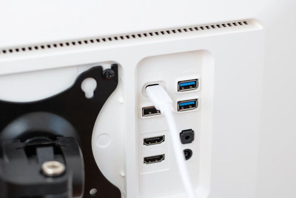
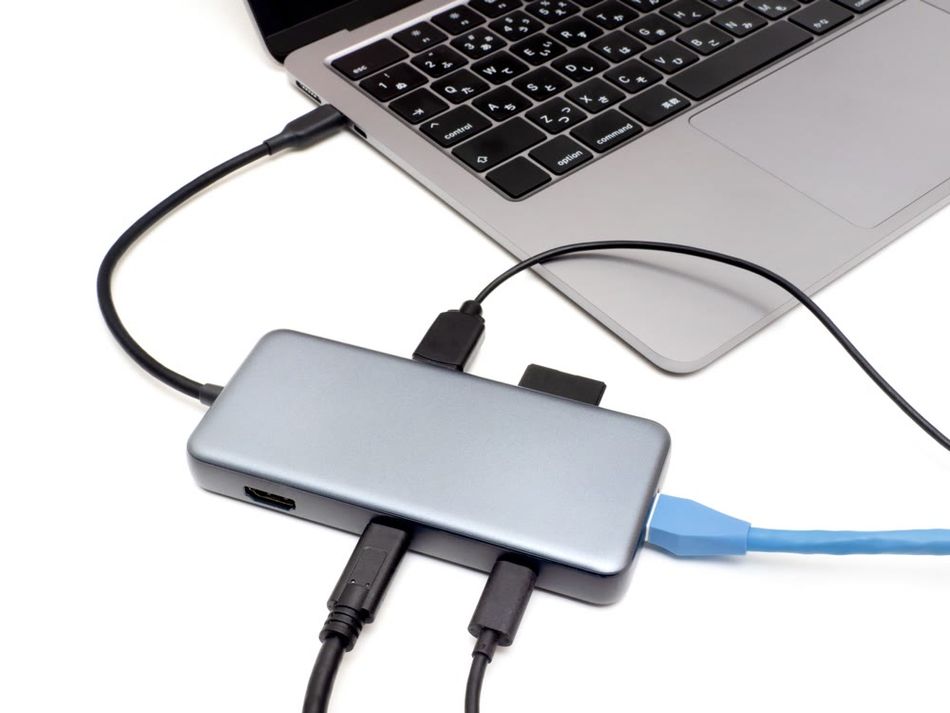
Laptop Docking Station (Power + Display + Data)
A Thunderbolt dock is an example of the USB-C pinout's multi-functionality.
Power and Data Convergence: The dock's upstream USB-C plug negotiates 100W (20V/5A) power to charge the laptop. Simultaneously, it handles two DisplayPort streams and USB data.
Video Output: Through PD communication on the CC pins, the dock advertises DisplayPort Alt Mode support. The laptop's GPU routes output into the USB-C connector's SuperSpeed lanes (4 lanes split into two DP streams) to power dual 4K monitors.
Peripheral Connectivity: The dock's internal hub utilizes the USB 2.0 pins (and potentially a single USB 3.x lane if configured for 2-lane DisplayPort) to maintain connectivity for peripherals, like keyboards and mice.
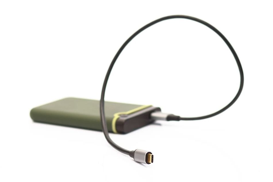
Bus-Powered External SSD (Self-Powered USB3 Peripheral)
A portable NVMe SSD leverages USB-C for both data and power, maximizing its performance capabilities.
Device Operation: The SSD’s USB-C port functions as a UFP (Upstream Facing Port) device.
Power Negotiation: It negotiates 5V/3A (15W) power from the host to supply its NVMe controller and drive.
High-Speed Data: When connected to a compatible host, it uses USB 3.2 Gen2x2 (20 Gbps), engaging both SuperSpeed TX/RX lane pairs on the USB-C pinout, enabling approximately 2 GB/s throughput.
Implementation / Deployment Best Practices
Successfully implementing the USB-C pinout demands meticulous attention to electrical, mechanical, and protocol details.
Design & Layout
Designers should follow USB-IF and IC vendor reference schematics for proper CC wiring, ESD protection, and power switch arrangements, which helps avoid common errors. For high-speed pins, PCB layout must treat SuperSpeed differential pairs as 85-90 Ω impedance-controlled microstrips or striplines, ensuring they are short, direct, and precisely length-matched.
Minimizing stubs and vias, and using proper ground vias around the connector, are also crucial for signal integrity and EMI reduction. When implementing Power Delivery circuitry, components like MOSFETs and power switches must be rated for continuous current, and VBUS decoupling capacitors should be sized according to spec to manage inrush. For bulk capacitance, designers should use inrush limiting or active discharge. Furthermore, VBUS and VCONN protection requires reversible polarity protection or ideal diode controllers for source ports and current limiting for VCONN, ensuring it only provides power when needed.
Robustness & Validation
Thermal and mechanical considerations are vital; high-current VBUS traces should be short and wide to manage heat, and connector ground tabs should be well-soldered to large copper areas for dissipation. Mechanically, reinforcing the connector with through-hole anchor pins helps mitigate cable pull stress, and component placement near the connector should allow for cable plug clearance. For testing and validation, a comprehensive plan is essential, including functional, stress, and interoperability tests. Designers should verify VBUS voltage drop under maximum load and use a USB protocol analyzer for data signal quality and error rates.
Firmware
In firmware, implementing timeouts and fail-safes is crucial; for instance, a device should default to a safe power mode if PD negotiation fails. Firmware must handle all USB-C states—attach, detach, negotiation, and error recovery. Leveraging provided libraries or state machine frameworks for PD control is highly recommended to manage complex scenarios like Hard Resets or Fast Role Swaps effectively.
Suggested Reading: Solving Fast Charging USB Type-C Cables Problems
Conclusion
The USB-C pinout is a remarkable engineering feat, consolidating extensive functionality into a compact, reversible connector. Its 24 pins intelligently manage everything from USB 2.0 to multi-gigabit USB4 data and scalable power delivery up to 240W, all coordinated by the Configuration Channel (CC) pins. For hardware designers, USB-C offers simplified connectivity but demands meticulous implementation due to its complex blend of analog, digital, and power signaling.
This article details USB-C's reversible pin layout, CC-based role detection, and the architectural nuances of receptacles, plugs, and cables, highlighting performance capabilities up to 80 Gbps and 240W. It emphasized best practices like using dedicated controller ICs, precise PCB design, and rigorous compliance testing to avoid common pitfalls. USB-C's adaptability, including Alternate Modes and flexible power delivery, positions it as the dominant future connector, making in-depth understanding crucial for engineers integrating it into diverse projects.
FAQ
Q1: What are the main groups of pins in the USB-C connector?
USB-C pins are grouped into power (VBUS/GND), high-speed data (TX/RX pairs for USB 3.x/USB4/Alt Modes), sideband use (SBU for auxiliary signals), USB 2.0 data (D+/D-), and Configuration Channel (CC) pins for negotiation and power delivery.
Q2: Why does USB-C have two CC pins and how do they work?
Dual CC pins enable orientation detection; only one connects based on plug insertion. They carry voltage for role and current capability detection and facilitate USB Power Delivery communication via a ~300 kHz BMC signal.
Q3: Can a USB-C port output video to a monitor?
Yes, via Alternate Modes like DisplayPort Alt Mode or Thunderbolt. The USB-C port reconfigures high-speed lanes for native video signals, requiring device support and an appropriate cable/adapter.
Q4: What is an “e-marker” cable and when is it required?
An e-marker cable contains a chip that communicates its capabilities to connected devices via the CC pin. It's required for cables supporting currents over 3A (e.g., 5A) or high speeds (USB 3.1 Gen2/USB4).
Q5: Are USB4 and Thunderbolt actually using the same USB-C connector and pinout?
Yes, USB4 and Thunderbolt 3/4 both utilize the USB-C connector and pinout. Thunderbolt operates via Alternate Mode, multiplexing PCIe and DisplayPort protocols over the USB-C lanes, which USB4 formalizes into its standard.
Q6: How can I protect my USB-C port hardware from damage or electrical issues?
Protect USB-C hardware using ESD protection diodes on signal lines, over-voltage and over-current protection on VBUS, and robust mechanical design with through-hole connectors. Proper PCB layout and testing are also crucial.
Q7: Can a USB-C port both charge a device and output data at the same time (and in both directions)?
Yes, a USB-C port can simultaneously handle power (in one direction at a time, but roles can swap) and full-duplex high-speed data. Power and data roles are independently negotiated via the CC pins.
References
USB Implementers Forum, "Compliance," USB-IF. [Online]. Available: https://www.usb.org/compliance.
D. Williams, "Guide to USB-C Pinout and Features," Technical Articles, All About Circuits. [Online]. Available: https://www.allaboutcircuits.com/technical-articles/introduction-to-usb-type-c-which-pins-power-delivery-data-transfer/ .
PinoutGuide.com, "USB-C (Type-C) pinout signals." [Online]. Available: https://pinoutguide.com/Slots/usb-type-c_pinout.shtml#google_vignette
SM Tech, "USB C Pinout - All USB 2.0-3.0 Type Pin Diagram." [Online]. Available: https://somanytech.com/usb-c-pinout-and-usb-type-c-connector-pinout-and-functional-details/
Wikipedia, "USB-C," Wikipedia.org. [Online]. Available: https://en.wikipedia.org/wiki/USB-C.
Granite River Labs, "Introduction to PD 3.1 – the Latest USB-IF Power Delivery Specification," Technical Blog. [Online]. Available: https://www.graniteriverlabs.com/en-us/technical-blog/usb-pd-merged-test-updates.
USB Implementers Forum, "USB Power Delivery (USB PD) Specification," USB.org. [Online]. Available: https://www.usb.org/usb-charger-pd.
in this article
1. Key Takeaways2. Introduction3. Foundational Principles & Terminology4. Architecture & Variants5. Performance Envelope (Speed & Power)6. Integration & Interoperability7. Tooling, Ecosystem & Standards8. Use-Cases for USB-C Type 9. Implementation / Deployment Best Practices10. Conclusion11. FAQ12. References