Raspberry Pi 4 Pinout: A Comprehensive Guide for Engineers
Explore the Raspberry Pi 4 pinout with detailed explanations of GPIO theory, power and ground distribution, communication interfaces (I²C, SPI, UART), PWM pins, and safety considerations to accelerate your hardware prototyping and development.

05 Dec, 2025. 15 minutes read
Key Takeaways
Standardized 40‑pin header: The Raspberry Pi 4 makes twenty‑eight BCM2711 GPIOs available via a 40‑pin header, including 26 configurable I/O pins plus dedicated power and ground pins.
Diverse functions: Pins support digital input/output, PWM, I²C, SPI, and UART communication protocols, enabling engineers to interface with a wide variety of sensors and peripherals.
Voltage and current considerations: Power pins supply 5 V and 3.3 V while ground pins ensure a stable reference; understanding electrical limits is vital for safe operation.
Theoretical foundation: GPIOs are uncommitted digital signal pins that are software‑controlled and have no predefined purpose—their behavior is defined by the system designer.
Practical implementation: Engineers can use Python libraries such as gpiozero and RPi.GPIO to toggle GPIOs, read inputs, generate PWM, and communicate over I²C/SPI/UART, enabling rapid prototyping and integration into larger systems.
Introduction
The Raspberry Pi 4 Model B has become a staple in modern embedded systems and digital design projects. Its combination of a powerful ARM‑based CPU, flexible memory configurations, and versatile I/O support makes it a favorite among digital design engineers, hardware developers, and electronics students. One of its most significant features is its 40‑pin General‑Purpose Input/Output (GPIO) header, commonly referred to as the Raspberry Pi 4 pinout. This header provides the primary interface for connecting external circuits, sensors, actuators, and communication modules to the board.
This comprehensive article provides an in-depth look at the Raspberry Pi 4 pinout. We’ll start with an overview of the Raspberry Pi 4 hardware to understand the context in which the GPIO header operates. Next, we’ll dive into the theoretical details of GPIOs. This is followed by a breakdown of the Raspberry Pi 4 pinout, covering the power pins, ground pins, general-purpose I/O pins, and special-purpose pins. After establishing this foundation, the article will explore practical implementation techniques, showcasing how to control LEDs, read sensor data, use PWM to modulate signals, and communicate with peripheral devices using I²C, SPI, and UART.
Whether you’re designing a complex digital system or learning how to integrate hardware into software projects, this guide will equip you with the knowledge and tools needed to work effectively with the Raspberry Pi 4’s GPIO pinout.
Raspberry Pi 4 Model B: Overview and Specifications
What is Raspberry Pi 4?
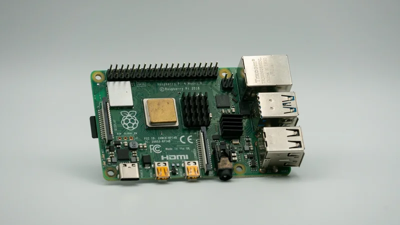
The Raspberry Pi 4 is a compact, low-cost single-board computer designed for learning, prototyping, and embedded system development. It runs a full Linux-based operating system stored on a standard SD card and includes a 40-pin GPIO header.
Before exploring the pinout, it’s important to understand the board’s broader architecture. Released in June 2019, the Raspberry Pi 4 Model B is a widely used Raspberry Pi board that represents a significant leap in performance and functionality compared to its predecessors. It offers a faster quad‑core Cortex‑A72 processor, improved memory options, and enhanced connectivity features such as gigabit Ethernet, dual‑band Wi‑Fi, and two micro HDMI ports for dual‑display support [1]. The board retains backward compatibility with earlier models’ GPIO layouts, making it an attractive, seamless upgrade for existing projects.
The key hardware specifications relevant to GPIO usage are summarized below:
Component | Specification (Pi 4 Model B) |
SoC | Broadcom BCM2711 (quad‑core ARM Cortex‑A72 @ 1.5 GHz) |
RAM options | 2 GB, 4 GB, or 8 GB LPDDR4 |
Power input | 5 V DC via USB‑C; requires 5 V/3 A supply |
GPIO header | 40‑pin (backwards compatible with Pi 3 and Pi 2) |
Supported voltages | 5 V pins (2), 3.3 V pins (2), 0 V ground pins (8) |
Onboard interfaces | 2× USB 2.0, 2× USB 3.0, Gigabit Ethernet, CSI/DSI camera/display connectors |
Importance of Backward‑Compatible Pinout
Raspberry Pi uses a standardized 40‑pin GPIO header across most of its single‑board computer lineup. The Pi 1 Model A and B originally provided a 26‑pin header, but subsequent models—including Pi 2, Pi 3, and Pi 4—adopted the full 40-pin layout [3]. This consistent layout enables engineers to design HATs (Hardware Attached on Top) and other peripheral modules that work across multiple Pi generations. The standardized pinout of the Raspberry Pi 4 allows engineers migrating projects from older Pi models to make minimal adjustments, simplifying upgrades and preserving compatibility.
Theoretical Concepts: Understanding GPIO
General‑Purpose Input/Output (GPIO) Fundamentals
A General Purpose Input/Output (GPIO) is a configurable digital signal pin on an integrated circuit or single-board computer that can be controlled by software. Unlike pins dedicated to specific functions (e.g., USB, HDMI), GPIOs have no predefined purpose. Engineers can assign them roles such as reading switches, controlling LEDs, generating pulse-width modulation (PWM) signals, or communicating via serial protocols like UART, I²C, and SPI. This flexibility is crucial in embedded system design, where hardware configurations vary widely across applications.
Key properties of GPIOs include:
Directionality: Each GPIO can be configured as an input or output. Inputs detect logical voltage levels (high or low), while outputs drive these levels onto connected circuits.
Voltage levels: On the Raspberry Pi, GPIO outputs operate at 3.3 V. Inputs are tolerant to up to 3.3 V; applying higher voltages can damage the CPU [2].
Drive strength: Each pin can source or sink limited current (typically up to ~16 mA). Overloading pins can cause board failure. For high-current loads, external drivers or transistors are recommended.
Pull-up/pull-down resistors: Software-configurable internal pull-up or pull-down resistors keep a GPIO pin at a stable logic level whenever it is left unconnected, preventing floating inputs.
Understanding these properties is essential for designing reliable hardware interfaces. For example, when interfacing with 5 V devices, engineers must incorporate voltage dividers or level shifters to protect the Pi’s 3.3 V GPIOs.
Pin Numbering Schemes
The Raspberry Pi supports two primary pin-numbering conventions:
Physical numbering: Pins correspond to their physical positions on the 40‑pin header (e.g., Pin 1 at the top left and Pin 40 at the bottom right). This scheme is intuitive when wiring circuits.
BCM (Broadcom) numbering: In this scheme, each pin is referenced by its Broadcom SoC GPIO identifier (e.g., GPIO2, GPIO3). Software libraries interact with these numbers because they map directly to the internal hardware registers.
Different libraries—such as RPi.GPIO, gpiozero, and pigpio—support one or both conventions, and many allow users to select which scheme to use. Maintaining a consistent numbering approach throughout a project is essential to avoid wiring or coding errors.
Raspberry Pi 4 Pinout: A Detailed Breakdown
Overall Structure
Raspberry Pi 4 provides 28 BCM-numbered GPIO lines on the 40-pin header, but only 26 of them are available for general-purpose use. GPIO0 (ID_SD) and GPIO1 (ID_SC) are reserved for the HAT ID EEPROM [3]. The header is arranged in two rows of 20 pins: the odd-numbered pins are on the outer row (near the board edge), and the even-numbered pins are on the inner row (closer to the board center).
The following table summarizes the pin categories on the Pi 4 header:
Category | Count | Notes |
5 V power pins | 2 | Provide 5 V from the USB‑C supply |
3.3 V power pins | 2 | Provide a regulated 3.3 V supply |
Ground pins (GND) | 8 | 0 V reference points |
GPIO pins | 26 | Configurable as input/output; support PWM, I²C, SPI, UART |
EEPROM pins | 2 | For HAT identification (ID EEPROM) |
Tip: Some pins are multiplexed and can serve multiple functions. Always check the datasheet before assigning pins to avoid conflicts.
Pinout Diagram
The following diagram helps engineers quickly reference the GPIO pinout of Raspberry Pi 4 with all pins labeled.
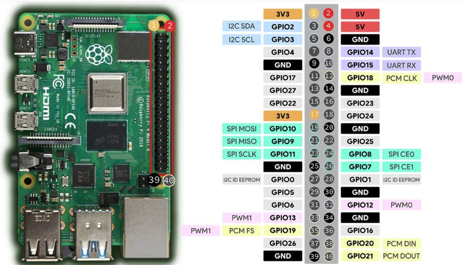
Now that the layout is clear, let's look at what each pin type actually does.
Power Pins
Power pins provide fixed voltage rails to external components. The Pi 4 includes two 5V pins (pins 2 and 4) that output the input voltage from the USB‑C power supply, and two 3.3V pins (pins 1 and 17) that offer regulated 3.3V power output from the onboard power circuitry. When using these rails, ensure the total current draw stays within the Pi’s power budget—excessive load can cause voltage drops, instability, or board damage.
The 5 V rail can supply up to roughly 2.5A (shared with the board when using a proper 3A power supply). The 3.3 V rail is limited to about 800 mA.
Ground Pins
Several pins on the header (pins 6, 9, 14, 20, 25, 30, 34, and 39) serve as a ground (0 V) reference. These ground pins are used to complete circuits and provide a common reference for stable logic levels. When connecting high-current devices, it’s best to place ground wires close to the power pins to minimize potential voltage drop and maintain signal integrity.
GPIO Pins
The 26 configurable I/O pins include general‑purpose digital lines as well as pins multiplexed with peripheral functions (I²C, SPI, UART, PWM, PCM). Engineers can consult the Broadcom datasheet for details on drive strength, slew rates, and alternate functions. By default, at boot, all GPIO pins are configured as inputs with no pull-up or pull-down resistors enabled.
The table below categorizes the pins by function:
Function | GPIO (BCM) | Notes |
PWM (hardware) | GPIO12, GPIO13, GPIO18, GPIO19 | Two channels; hardware PWM via clocks |
SPI0 | GPIO9 (MISO), GPIO10 (MOSI), GPIO11 (SCLK), GPIO8 (CE0), GPIO7 (CE1) | Primary SPI bus (CE1 optional) |
SPI1 | GPIO19 (MISO), GPIO20 (MOSI), GPIO21 (SCLK), GPIO18 (CE0), GPIO17 (CE1), GPIO16 (CE2) | Secondary SPI bus (requires dtoverlay=spi1-3cs) |
I²C | GPIO2 (SDA1), GPIO3 (SCL1) | Standard I²C bus; 1.8 kΩ pull-ups on board |
EEPROM | GPIO0 (ID_SD), GPIO1 (ID_SC) | Used to read HAT ID EEPROM; normally disabled |
UART | GPIO14 (TXD0), GPIO15 (RXD0) | Default serial console; must be disabled to use as a general UART |
PCM | GPIO18 (CLK), GPIO19 (FS), GPIO20 (DIN), GPIO21 (DOUT) | Alternative functions for audio (I²S) |
General I/O | GPIO4, 5, 6, 17, 22, 23, 24, 25, 27, 26, 16, 12, 13, 19, 20, 21 | Configurable as input/output; some support PWM or alternate functions |
Also, when assigning pins, avoid conflicts between multiple functions. For example, using GPIO18 for PWM may interfere with audio I²S if that function is enabled.
Recommended Reading: Meet the new Raspberry Pi 5
Communication Protocols and Special Interfaces
The Raspberry Pi 4 exposes several dedicated pins that support industry-standard communication protocols. These interfaces—such as I²C, SPI, UART, PWM, and PCM/I²S—allow the Pi to interact with sensors, displays, actuators, audio hardware, and other digital systems. Below is a detailed look at each protocol and how it is implemented on the Pi 4.
I²C (Inter‑Integrated Circuit)
I²C is a two‑wire serial bus used to connect multiple slave devices over a shared clock (SCL) and data line (SDA) [4]. On the Raspberry Pi 4, the default I²C bus (I²C1) uses GPIO2 for SDA and GPIO3 for SCL. The ID-EEPROM bus (I²C0) on GPIO0 and GPIO1 is reserved for HAT identification. To use I²C, enable the interface via raspi-config or by adding dtparam=i2c_arm=on to /boot/config.txt. Pull‑up resistors are already present (1.8 kΩ), though additional pull-ups may be needed for high-speed devices or longer wiring.
I²C supports 7-bit and 10-bit addressing with typical speeds of 100 kHz (standard mode), 400 kHz (fast mode), and up to 1 MHz (fast-mode plus). Many sensors, RTCs, and low-speed peripherals rely on this interface.
SPI (Serial Peripheral Interface)
Serial Peripheral Interface (SPI) is a full‑duplex synchronous serial bus that uses separate lines for clock (SCLK), master‑out‑slave‑in (MOSI), master‑in‑slave‑out (MISO), and chip‑select (CE). The primary SPI bus on the Raspberry Pi 4 uses GPIO10 (MOSI), GPIO9 (MISO), GPIO11 (SCLK), GPIO8 (CE0), and GPIO7 (CE1).
A secondary bus, SPI1, can be enabled through a device tree overlay and provides up to three chip-select lines on GPIO18–21. SPI is commonly used for high-speed devices such as displays, ADCs, DACs, and RF modules.
UART (Universal Asynchronous Receiver/Transmitter)
UART provides asynchronous serial communication for debugging consoles and interfacing with serial devices such as GPS modules or Bluetooth modules. The primary UART uses GPIO14 (TXD0) and GPIO15 (RXD0). By default, it is mapped to the Linux serial console; to repurpose it, the console must be disabled in /boot/cmdline.txt, and the hardware UART enabled via enable_uart=1. The Pi also exposes a secondary mini UART on GPIO32/33, but these pins are not on the 40‑pin header, so it is not typically used in GPIO-based projects.
PWM (Pulse‑Width Modulation)
Hardware PWM is available on GPIO12, GPIO13, GPIO18, and GPIO19. PWM enables analog-like control through duty-cycle modulation, suitable for LEDs, motors, and servos. The Pi 4’s PWM channels can be driven via the pigpio library for precise timing or via gpiozero for simpler applications. Software PWM can be generated on any GPIO, but hardware PWM offers lower jitter and CPU usage.
PCM/I²S Audio
The Pi 4 can output digital audio via the Pulse Code Modulation (PCM)/I²S interface using GPIO18–21 in alternative functions. This is useful for connecting external audio DACs. These pins share functionality with SPI1 and PWM, so only one function can be active at a time.
Electrical Considerations and Safety
Voltage Levels
All Raspberry Pi GPIO pins operate at 3.3 V logic. They are not 5‑V tolerant, so connecting a 5V signal directly to a GPIO can cause irreversible damage to the Broadcom SoC [2].
When interfacing with 5‑V devices, use bidirectional level shifters, voltage dividers for simple inputs, and transistor drivers or MOSFETs for outputs that need to switch higher voltages or currents.
Current Limits
Each GPIO pin can safely source or sink up to ~16 mA, but long-term operation should usually stay below that for reliability. The total current drawn from all GPIOs should not exceed 50 mA to prevent damage. Additionally, the 5 V and 3.3 V power pins share the same supply rails that power the Pi. Attaching high-power modules (relays, LED strips, servo motors) directly to these pins can cause voltage drops and instability.
Whenever possible, power external loads using an independent regulated supply with a common ground.
Pull‑Up and Pull‑Down Resistors
The Pi’s GPIOs support configurable internal pull‑up and pull‑down resistors to keep inputs from floating when not actively driven. For example, when reading a push‑button, enable a pull‑down resistor so the input reads low when the button is not pressed. These resistors can be configured in software using libraries such as gpiozero (the Button class) or RPi.GPIO (setup(pin, GPIO.IN, pull_up_down=GPIO.PUD_UP)).
Protecting Against Inductive Loads
Inductive components such as motors, solenoids, and relay coils can generate large back-EMF spikes when switched off.
Add flyback diodes across inductive loads
Use transistor/MOSFET driver stages or relay driver boards
For DC motors: use an H-bridge motor driver
For stepper motors: use a current-controlled stepper driver
Never drive inductive loads directly from a GPIO pin.
Static Discharge
While the Pi has some internal ESD protection, exposed GPIO pins remain vulnerable. To reduce the risk of electrostatic discharge damage:
Ground yourself before handling components
Avoid connecting/disconnecting wires while the Pi is powered
Use antistatic precautions when working in dry or carpeted environments
Practical Implementations
Choosing a Programming Library
Several software libraries are available for controlling GPIOs on the Raspberry Pi:
gpiozero: High-level Python API with abstractions for LEDs, buttons, sensors, PWM devices, etc. Excellent for rapid prototyping and education.
RPi.GPIO: Lower-level Python library offering direct control of GPIO pins, event detection, pull-up/down configuration, and software PWM.
pigpio: High-performance GPIO control using DMA for precise PWM, pulse timing, and waveforms, suitable for robotics and real-time control.
WiringPi (deprecated): Legacy C library no longer actively maintained but present in older projects.
The following examples demonstrate common use cases using gpiozero and RPi.GPIO.
Example 1: Blinking an LED
Hardware: Connect an LED’s anode to GPIO17 (Pin 11) through a 330 Ω resistor and its cathode to GND (Pin 9).
# Using gpiozero
from gpiozero import LED
from time import sleep

led = LED(17)  # BCM numbering
while True:
    led.on()
    sleep(0.5)
    led.off()
    sleep(0.5)
This code toggles the LED every half‑second. gpiozero handles pin setup and cleanup automatically.
Example 2: Reading a Push Button
Hardware: Connect a push button between GPIO27 (Pin 13) and 3.3 V (Pin 1). The internal pull‑down resistor keeps the input low until the button is pressed.
import RPi.GPIO as GPIO
import time


GPIO.setmode(GPIO.BCM)
GPIO.setup(27, GPIO.IN, pull_up_down=GPIO.PUD_DOWN)


try:
    while True:
        if GPIO.input(27):
            print("Button pressed!")
        time.sleep(0.1)
except KeyboardInterrupt:
    pass
finally:
    GPIO.cleanup()
Example 3: Controlling a Servo with PWM
Hardware: Connect a servo’s control wire to GPIO18 (Pin 12). Provide power to the servo from a separate 5 V supply (do not power the servo from the Pi’s 5 V pin; this may draw too much current). Connect the grounds.
from gpiozero import Servo
from time import sleep


# gpiozero’s Servo uses software PWM by default.
servo = Servo(18, min_pulse_width=0.5/1000, max_pulse_width=2.5/1000)


while True:
    servo.min()   # -90 degrees
    sleep(1)
    servo.mid()   # 0 degrees
    sleep(1)
    servo.max()   # +90 degrees
    sleep(1)
Use pigpio for more precise servo control if jitter becomes an issue.
Example 4: Interfacing with an I²C Temperature Sensor
Hardware: Attach an MCP9808 (or similar I²C sensor) to I²C bus pins:
GPIO2 – SDA (Pin 3) and GPIO3 – SCL (Pin 5). Use a pull‑up if necessary.
import smbus2
import time


bus = smbus2.SMBus(1)  # I²C bus 1
MCP9808_ADDR = 0x18


# Read temperature register
def read_temp():
    temp_msb, temp_lsb = bus.read_i2c_block_data(MCP9808_ADDR, 0x05, 2)
    temp = ((temp_msb & 0x1F) << 8) | temp_lsb
    if temp & 0x1000:  # sign bit
        temp -= 4096
    celsius = temp * 0.0625
    return celsius


while True:
    print(f"Temperature: {read_temp():.2f} °C")
    time.sleep(1)
Example 5: SPI Communication with an ADC
Hardware: Connect an SPI ADC (e.g., MCP3008) to SPI0 pins: CE0 (GPIO8), MOSI (GPIO10), MISO (GPIO9), SCLK (GPIO11), plus 3.3 V and GND.
import spidev
import time


spi = spidev.SpiDev()
spi.open(0, 0)  # bus 0, device 0 (CE0)
spi.max_speed_hz = 1350000


def read_adc(channel):
    # MCP3008 expects 3 bytes: start bit (1), single-ended + channel bits, don’t care
    cmd = [1, (8 | channel) << 4, 0]
    response = spi.xfer2(cmd)
    result = ((response[1] & 3) << 8) | response[2]
    return result


try:
    while True:
        value = read_adc(0)
        voltage = value * 3.3 / 1023
        print(f"ADC reading: {value}, Voltage: {voltage:.2f} V")
        time.sleep(0.5)
except KeyboardInterrupt:
    spi.close()
Example 6: UART Communication with a GPS Module
Hardware: Connect a GPS module’s TX to GPIO15 (RXD0) and its RX to GPIO14 (TXD0). Disable the serial login console and enable UART. Use pyserial to read NMEA sentences.
import serial
ser = serial.Serial("/dev/serial0", baudrate=9600, timeout=1)
try:
    while True:
        line = ser.readline().decode("ascii", errors="replace")
        if line.startswith("$GPGGA"):  # GPS fix data
            print(line.strip())
except KeyboardInterrupt:
    ser.close()
Practical Applications for Engineers
Digital Design Prototyping
Digital design engineers often use the Raspberry Pi 4 as a test platform to prototype firmware and hardware simultaneously. The 40-pin GPIO header provides easy connectivity to logic analyzers, FPGAs, and digital ICs.
For example, an FPGA development board can interface with the Pi using SPI, UART, or GPIO-based parallel signals to offload high-speed operations while the Pi runs high-level control and software logic.
The standardized 40-pin layout ensures broad compatibility with HATs that may include level shifting, ADC/DAC expansion, or isolation circuits, extending the Pi’s digital interfacing capabilities.
Embedded Systems and IoT
The Pi’s built‑in Ethernet and Wi‑Fi, combined with its GPIO, make it an ideal gateway for IoT devices. Engineers can use the Pi 4 to collect data from sensors via I²C or SPI and forward it over the network. The board can act as an edge computing node, processing data locally and sending results to cloud services.
Robotics and Mechatronics
The Raspberry Pi 4’s GPIO capabilities make it an excellent platform for robotics and mechatronics projects. Hardware PWM pins allow precise control of servos, electronic speed controllers (ESCs), and DC motor drivers, enabling smooth and accurate actuation. By integrating PWM outputs with feedback sensors—such as quadrature encoders monitored via GPIO interrupts—engineers can implement closed-loop motion control for robots and automated mechanisms.
For CPU-intensive tasks like computer vision, navigation, or machine learning, the Pi 4 can run frameworks such as OpenCV, TensorFlow Lite, or ROS locally, allowing autonomous decision-making and real-time data processing. However, time-critical motion control is usually delegated to dedicated motor driver ICs or a co-processor connected via UART or I²C, ensuring precise timing while the Linux OS handles higher-level processing.
Education and Experimentation
For electronics students, the Raspberry Pi 4 serves as an accessible platform to learn digital logic, communication protocols, and software-driven hardware control. Using breadboards and simple components, students can experiment with circuits, measure signals with oscilloscopes, and understand the interplay between software and hardware.
Its large ecosystem of tutorials and HATs makes the Pi ideal for STEM labs, electronics clubs, and maker projects.
Optimizing GPIO Performance on Raspberry Pi 4
Interrupt Handling
Polling inputs can be inefficient, especially when dealing with multiple sensors. Most GPIO libraries support interrupts or callbacks triggered by edge events (rising, falling, or both). For instance, RPi.GPIO’s add_event_detect() or gpiozero’s event methods allow executing functions when a state change occurs. Proper use of interrupts reduces CPU usage and improves responsiveness.
DMA‑Based Timing
For high‑frequency signal generation or capture, software bit‑banging may be too slow or jittery. Libraries like pigpio use DMA to create waveforms with microsecond precision, enabling applications such as digital audio, IR communication, or capturing logic analyzer traces.
Simultaneous Multithreading (SMT)
The Pi 4’s quad‑core CPU allows running multiple threads concurrently. Engineers can assign separate threads to handle different tasks: one for reading sensors, another for communication, and a third for the user interface. Care must be taken to prevent race conditions when multiple threads access shared GPIO resources.
Real‑Time Considerations
Linux is not a real‑time operating system; thus, timing can vary due to scheduling. For strict real‑time requirements, consider using a real‑time kernel or offloading tasks to microcontrollers. Alternatively, use the Pi 4 with a microcontroller (e.g., Arduino or Raspberry Pi Pico) over serial or SPI, letting the microcontroller handle real‑time tasks.
Conclusion
The Raspberry Pi 4’s standardized 40‑pin header is a powerful gateway to the physical world. By understanding the theoretical foundations of GPIOs and the specific functions each pin supports, engineers can design sophisticated systems that integrate hardware and software seamlessly. Key takeaways include the availability of 28 GPIO-capable pins via the 40-pin header, with 26 available for general I/O. With careful attention to voltage and current limitations, engineers can avoid common pitfalls like overdriving pins or damaging the board.
Practical examples—such as blinking LEDs, reading buttons, controlling servos, and interfacing with sensors—illustrate how these concepts translate into real‑world applications.
Whether you’re a digital design engineer prototyping a new product, a hardware engineer integrating custom circuitry, or an electronics student learning the ropes, mastering the Raspberry Pi 4 pinout equips you with versatile tools to bring your ideas to life.
FAQ
1. How many GPIO pins does the Raspberry Pi 4 have?
The Raspberry Pi 4 exposes twenty‑eight BCM2711 GPIOs via a 40‑pin header, including 26 configurable GPIO pins plus dedicated power and ground pins. The remaining pins provide power (5 V and 3.3 V), ground, and dedicated functions such as EEPROM communication.
2. Are the Pi 4’s GPIO pins 5‑V tolerant?
No. The GPIO pins operate at 3.3 V logic levels and are not 5‑V tolerant. Applying 5 V directly to a GPIO pin can permanently damage the SoC [2]. Use level shifters or voltage dividers when interfacing with 5‑V devices.
3. What protocols are supported on the GPIO header?
The Pi 4 supports I²C (SDA1 on GPIO2, SCL1 on GPIO3), SPI (SPI0 on GPIO9–11 and SPI1 on GPIO16–21 with overlays), UART (TXD0 on GPIO14, RXD0 on GPIO15) and hardware PWM (GPIO12, 13, 18, 19). Some pins share multiple functions, so you must choose which function to enable via device tree overlays.
4. Can I use all 26 GPIO pins simultaneously?
You can use all 26 GPIO pins as inputs or outputs, but consider shared functions and system uses. For example, GPIO14/15 are used for the serial console by default, and GPIO0/1 are reserved for the ID EEPROM. Disable or reconfigure these functions before repurposing the pins.
5. How do I enable I²C or SPI on the Raspberry Pi 4?
Use the raspi-config utility (sudo raspi-config), navigate to Interface Options, and enable I²C or SPI. Alternatively, add dtparam=i2c_arm=on or dtparam=spi=on to /boot/config.txt and reboot. For SPI1, add dtoverlay=spi1-3cs.
6. What’s the difference between physical and BCM numbering?
Physical numbering refers to the pin’s position on the header (Pin 1–40). BCM numbering refers to the Broadcom SoC’s GPIO numbers (e.g., GPIO17). Libraries may use one scheme or allow selection; always confirm which scheme you’re using to avoid wiring errors.
7. Are Raspberry Pi pinouts consistent across models?
Yes. All Raspberry Pi models since the B+ use the same 40‑pin header with identical pin functions. Earlier models (Pi 1 A/B) used a 26‑pin header [3]. This consistency allows HATs and accessories designed for one model to work on others without rewiring.
References
[1] Raspberry Pi Foundation, Raspberry Pi 4 Model B Datasheet, v1.2, June 2019. [Online]. Available: https://datasheets.raspberrypi.com/rpi4/raspberry-pi-4-datasheet.pdf
[2] C. Ee, “What are the specifications of the GPIO pins in Raspberry Pi 4 Model B?” DEV Community, 20‑Jul‑2021. [Online]. Available: https://dev.to/carolineee/what-are-the-specifications-of-the-gpio-pins-in-raspberry-pi-4-model-b-dje
[3] J. Smith, “GPIO Voltage and Current Limits on Raspberry Pi 4,” Random Nerd Tutorials, 2021. [Online]. Available: https://randomnerdtutorials.com/raspberry-pi-gpio-guide
[4] I²C,” SparkFun Learn, https://learn.sparkfun.com/tutorials/i2c/all (accessed Dec. 04, 2025).
in this article
1. Key Takeaways2. Introduction3. Raspberry Pi 4 Model B: Overview and Specifications 4. Theoretical Concepts: Understanding GPIO5. Raspberry Pi 4 Pinout: A Detailed Breakdown6. Communication Protocols and Special Interfaces7. Electrical Considerations and Safety8. Practical Implementations9. Practical Applications for Engineers10. Optimizing GPIO Performance on Raspberry Pi 411. Real‑Time Considerations12. Conclusion13. FAQ14. References