Relay Wiring Diagrams: Understanding 4-Pin and 5-Pin Connections
This article is a comprehensive technical guide to relay wiring diagrams, covering 4-pin and 5-pin configurations, working principles, safety practices, standards, and advanced relay applications in modern systems.

03 Apr, 2026. 13 minutes read
Key Takeaways
Understand the Core Concepts: Relay is an electromechanical or solid-state switch controlled by a coil. Knowing how normally open (NO) and normally closed (NC) contacts work and how to read schematic symbols is fundamental.
Use Correct Pin Assignments: ISO/DIN 72552 standardizes relay pins. Pin 30 is the common terminal, pins 85 and 86 connect to the relay coil, pin 87 is normally open and pin 87a is normally closed. Using the standard prevents miswiring and simplifies troubleshooting.
Protect the Circuit from Inductive Spikes: De-energizing the relay coil induces a voltage spike proportional to the change in current (V = -L x di/dt). A flyback diode or snubber network across the coil safely dissipates this energy.
Match Relays to Loads and Wire Sizes: Select relay contact ratings and wire gauge according to load type and length. When switching inductive loads, derate contacts to about 40% of the resistive rating and use appropriate fuse placement and protection.
Troubleshoot Safely: Test coil continuity and resistance with a multimeter; typical DC coils have less than 400 ohms while AC coils may exceed 10 kilohms. Check continuity between common (pin 30) and NO/NC contacts with the coil energized and de-energized.
Plan for Future Technologies: The solid-state relays offer faster switching and no arcing. Emerging power modules and smart relays are integrating diagnostics and remote control.
Introduction
Relays appear everywhere in modern electronics, from automotive lighting circuits to factory automation systems. They allow a low-power control circuit to govern a high-current or high-voltage load. The relay wiring diagrams provide a clear visual representation of how relay terminals, coils, and switching contacts are interconnected within a circuit.
Both 4-pin and 5-pin relays are widely used in automotive, industrial, and embedded applications, each offering distinct switching configurations. The properly interpreted relay wiring diagram helps identify terminal functions such as common (COM), normally open (NO), and normally closed (NC) contacts, ensuring correct integration into the electrical circuit.
This article serves as an engineering reference for digital design engineers, hardware engineers and technicians. It synthesizes standards, practical wiring practices and troubleshooting methods while optimizing for search terms relevant to relay wiring diagrams.
Fundamental Relay Operation
Electromechanical Relays
The electromechanical relay switch operates through the interaction of an electromagnet and a mechanical set of contacts, forming the basis of many relay circuit designs. The typical structure includes:
Frame or Housing: Provides mechanical support and electrical insulation, ensuring safe operation in high voltage or automotive environments.
Coil: It’s a wire wound around the ferromagnetic core. Once connected to a power source, it draws low current and generates a magnetic field proportional to ampere-turns, enabling control of high current loads.
Armature: Movable ferromagnetic element that responds to the magnetic flux, enabling rapid mechanical actuation.
Contacts: Conductive pads that open or close circuits. They are categorized as normally open (NO), normally closed (NC) or changeover (SPDT).
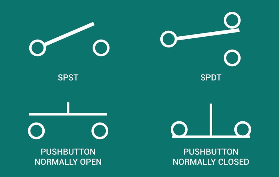
In a simple Single-Pole Single-Throw (SPST) relay, there is one common terminal and one normally open contact. When the coil is not energized, the NO contact is open; when the coil is energized, the electromagnet pulls the armature and closes the contact. In a Single-Pole Double-Throw (SPDT) relay, there are both NO and NC contacts; energizing the coil transfers the common terminal from one contact to the other. [1]
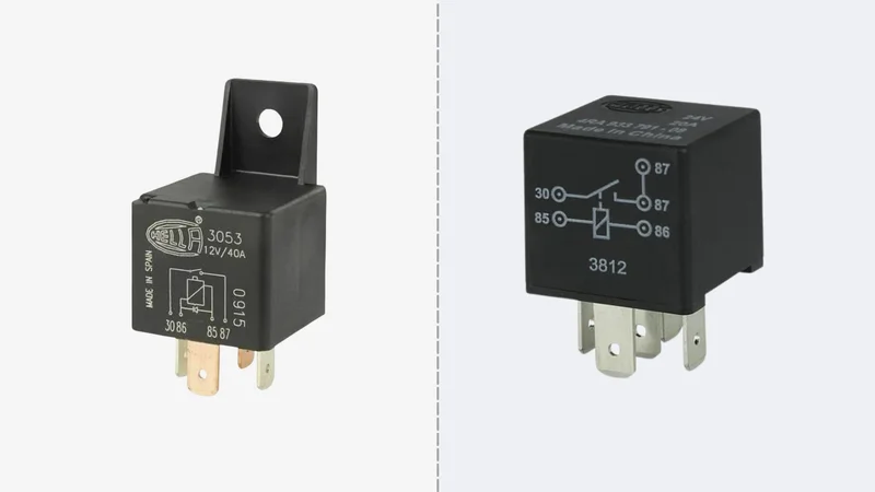
Relays are rated by coil voltage (e.g., 12 VDC, 24 VDC) and contact ratings. The contact ratings include maximum voltage, current and power. When selecting a relay, choose a contact rating that exceeds the expected load. For example, in automotive applications, a 5 pin relay or 4 pin relay is often used to isolate low-power control signals from high power devices such as motors or a light bulb circuit.
Solid-State Relays
The solid-state relays use transistors or triacs controlled by an optically isolated input. They switch faster than mechanical relays and have no moving parts, eliminating contact wear and arcing. However, SSRs introduce on-state resistance, thermal losses, and leakage currents, which must be considered in circuit diagram design.
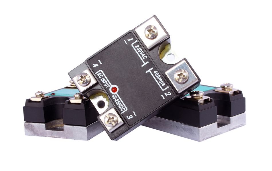
Unlike EMRs, SSRs may not follow conventional relay wiring diagram terminal standards. For high-frequency switching or silent operation, SSRs are preferred; for circuits requiring galvanic isolation and low on-resistance, EMRs remain popular.
Normally Open vs. Normally Closed
In relay terminology, normally open contacts remain open until the coil is energized, allowing current flow only when the relay is activated. Conversely, normally closed contacts conduct in the idle state and open upon energization. SPDT relays combine both behaviors, enabling flexible load control and redundancy in relay wiring configurations.
Coil Polarity and Inductive Behavior
The relay coil exhibits inductive characteristics, meaning current changes are not instantaneous. Most DC relays define polarity, particularly when a suppression diode or resistor is integrated across the coil. Incorrect polarity can prevent proper suppression and damage control electronics.
Once the relay is de-energized, the collapsing magnetic field generates a voltage spike (back EMF), described by:
V = - L x (di/dt)
This transient can reach several hundred volts, posing risks to semiconductors and control circuits. Proper suppression using a flyback diode is critical in any robust relay wiring diagram, especially in sensitive or low voltage control systems.
Recommended Reading: What Is the Difference Between SPST, SPDT and DPDT? A Comprehensive Guide for Engineers
Relay Wiring Diagrams and Standards
ISO/DIN 72552 Terminal Numbering
Standardization is critical for interpreting any relay wiring diagram accurately. The DIN 72552 system defines terminal numbers based on function, ensuring consistency across automotive and industrial relay wiring applications. [2]
Terminal | Description | Wiring Notes |
30 | Common Supply/Input | Connects to positive power source; common to both NO and NC contacts |
85 | Coil Negative | Connects to ground or negative power; must match coil polarity if a diode is installed |
86 | Coil Positive | Connects to positive control signal or switch; energizing this pin energizes the coil |
87 | Normally Open (NO) Output | When the coil is energized, 30 connects to 87 to supply the load |
87-A | Normally Closed (NC) Output | Present on 5-pin changeover relays. When de-energized, 30 connects to 87-A; energizing disconnects 87-A and connects 87 |
This numbering system simplifies reading any wiring diagram or circuit diagram, especially when working across multiple relay manufacturers.
4-Pin Relay Wiring
The 4 pin relay typically follows a Single Pole Single Throw (SPST) configuration, commonly used for switching a single circuit.
Once the relay coil is energized, the internal electromagnet pulls the armature, closing the normally open relay contact and allowing current flow from 30 to pin 87. This separation of control and load circuits is a key advantage in automation and high power applications.
5-Pin Relay Wiring
The 5 pin relay operates as a Single Pole Double Throw (SPDT) device, offering both normally open and normally closed paths.
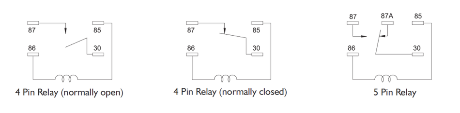
This configuration allows flexible control logic. For example, a load can remain active in the default state via 87-A, or only activate when the relay is energized via pin 87. Such versatility makes 5 pin relay designs essential in automotive control systems and advanced relay circuit designs.
Relay Schematic Symbols
When reading a schematic, the relay coil is represented by a winding symbol, and contacts are shown separately. The NO contact is drawn with a gap, whereas the NC contact shows a closed line. The dotted line often links the coil and contact to indicate they are mechanically linked.
Recommended Reading: What Are Schematics: The Blueprint Language of Engineering Decoded
Applications and Circuit Design
Load Types and Derating
The contacts suffer wear due to arcing when switching. When switching purely resistive loads, manufacturers typically specify the rated voltage and current. However, loads are often inductive (motors, solenoids) or capacitive (lighting).
Load Type | Derating Factor | Rationale |
Resistive | 75% of Rated Current | Contacts experience minimal arcing; small reduction extends life |
Inductive (Coils, Solenoids) | 40% | Stored energy causes arcing during opening; use snubbers |
Capacitive (Power Supplies, LED Drivers) | 75% | In-rush currents require modest derating |
Motor | 20% | Motors have high starting current and back-EMF, leading to heavy arcing |
Incandescent | 10% | Cold filament draws 10 to 15x steady current |
For example, a relay with a 10 A current rating should be limited to ~4 A when switching an inductive load. Exceeding limits accelerates erosion, increases contact resistance, and may lead to welding,especially in high current applications.
Wire Gauge and Voltage Drop
The wire selection directly impacts efficiency and safety in relay wiring. Conductors must support both current rating and acceptable voltage drop. In a 12 V automotive system, maintaining <2% drop is standard. For a 20 ft round-trip at 15 A, 12-AWG wire is recommended. The excessive resistance increases I²R losses:
2% drop (0.24 V at 12 V) ≈ 4.8 W heat at 20 A
20% drop (2.4 V) ≈ 48 W heat
Such losses can overheat insulation, degrade performance, and reduce delivered voltage to the load, especially in low voltage systems.
Fuse Placement and Overcurrent Protection
The fuse should be placed on the supply side of the relay (near the battery) so that any short circuit or overload between the battery and relay is interrupted. Placing a fuse after the relay leaves the upstream wiring and relay contacts unprotected, which can result in arcing, welding or fire.
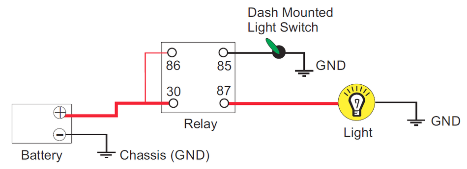
Example - Automotive Fuel Pump Circuit
The typical automotive fuel pump control uses a 4 pin relay in an SPST configuration:
Connect the coil negative (pin 85) to chassis ground
Connect the coil positive (pin 86) to the ignition switch or ECU output
Connect pin 30 to a fused supply from the battery (e.g., 30 A fuse located near the battery)
Connect pin 87 to the fuel pump positive terminal
Once the ignition key is turned, the ECU energizes the coil, the contact closes, and 12 V flows to the pump. The diode across the coil prevents voltage spikes.
Recommended Reading: Contactor vs Relay: Understanding the Differences and Applications
Flyback Diode and Surge Suppression
Back EMF and Voltage Spikes
In any relay circuit, the relay coil behaves as an inductor, storing energy in its magnetic field. Once the coil is de-energized, this energy must be released. According to Faraday’s law (V = -L di/dt), a rapid current interruption generates a high voltage spike (back EMF). [3]
In practical relay wiring, this spike can exceed hundreds of volts—even in low voltage systems; and may damage sensitive components such as transistors, MOSFETs, or microcontrollers. Proper suppression is therefore essential in every relay wiring diagram, especially in automation and automotive control circuits.
Flyback Diodes
The diode is placed in parallel with the coil, oriented in reverse bias relative to the supply. When the coil is energized, the diode blocks current. When the coil is de-energized, the induced voltage forward biases the diode, allowing current to circulate through the coil until the magnetic field collapses. This protects the driver circuit and stabilizes the relay switch operation.
In most schematic designs, general-purpose diodes (e.g., 1N400x series) are selected with a rating of 2–3× the coil voltage and sufficient current handling capacity.
Effects on Release Time
Placing a diode slows the rate at which the coil current decays. Without a diode, a typical automotive relay releases in about 2 ms; with a diode, release time increases to 9 to 10 ms. To mitigate this, designers sometimes use a resistor or a diode-Zener combination.
Resistor Suppression and Snubber Networks
To balance protection and speed, alternative suppression methods are used:
Resistor across Coil: Limits current decay while reducing delay (e.g., 680 Ω for a 12 V coil → ~2.5 ms release)
Diode + Zener Combination: Clamps voltage at a higher level, allowing faster energy dissipation
RC Snubber: Used in high voltage or inductive load switching to reduce arcing across switching contacts
These techniques improve performance while maintaining protection, making them essential considerations in advanced circuit diagram and relay wiring diagram design.
Recommended Reading: Finding the Sweet Spot for Flyback Converters in Electric Vehicles
Comparing Electromechanical and Solid-State Relays
Understanding the differences between electromechanical and solid state relays is essential when selecting the right device for a relay circuit, particularly in applications involving high current, high voltage, or fast automation control.
Characteristic | Electromechanical Relay (EMR) | Solid-State Relay (SSR) |
Operation | Uses coil and movable armature to open/close mechanical contacts | Uses semiconductor devices (triacs, transistors) triggered by opto-isolators |
Switching Speed | Slower (10 to 50 ms) | Fast (microseconds to milliseconds) with virtually unlimited switching cycles |
Contact Wear and Arcing | Contacts wear over time; arcing occurs when switching high current or inductive loads | No moving parts; arc-free switching; lifetime limited by thermal cycling |
Isolation | Provides galvanic isolation between coil and contacts | Also provides isolation via optocoupler |
On-Resistance | Very low (milliohms), minimal voltage drop | Higher on-state resistance causing heat; sometimes requires heat sinking |
Cost | Typically lower | Higher; cost justified when silent or high-speed switching is required |
Testing and Troubleshooting Relays
Continuity and Resistance Tests
With the relay removed from the circuit, set a multimeter to continuity mode and place probes across the coil terminals (pins 85 and 86). A beep indicates a closed coil; no beep suggests an open coil or broken wire. Measuring resistance in ohms provides additional confirmation. Typical DC relay coils have resistance below 400 ohms; AC coils may exceed 10 kilohms. Deviations from datasheet values may indicate damage. [4]

For SPDT relays, test the contacts. In the de-energized state, there should be continuity between pin 30 and the NC terminal (87-A) and no continuity between 30 and 87. When the coil is energized, continuity should switch: pin 30 should conduct to 87 and not to 87-A.
Diagnosing Stuck or Welded Contacts
A relay that remains in the ON state after the control signal is removed typically indicates welded contacts. This failure mode is common in high current or high power applications where excessive inrush current or inductive voltage spike causes localized heating and fusion of the contact surfaces. Such issues often arise when proper derating is ignored or when suppression components like a diode are absent. In these cases, replacing the relay is necessary, but it is equally critical to analyze the root cause within the circuit diagram, including load characteristics and protection strategy.
Evaluating Control Side and Supply Conditions
Beyond the relay itself, troubleshooting must extend to the control side of the relay wiring. Insufficient drive voltage, incorrect polarity, or unstable signals from a microcontroller or switch can prevent the relay from actuating reliably. Verifying that the power source delivers the correct voltage to the coil under load conditions is essential. In low voltage systems, even minor drops can prevent proper energization, while in automotive environments, transient fluctuations must also be considered.
Thermal and Mechanical Failure Indicators
Thermal stress and mechanical fatigue are long-term reliability concerns in relays. Discoloration, melted housing sections, or a burnt odor often indicate overheating due to excessive current or poor contact resistance. Mechanical degradation, such as weakened springs or worn armatures, can lead to delayed switching or intermittent operation. These failure modes highlight the importance of proper relay wiring diagram design, correct current rating selection, and effective surge suppression to ensure consistent performance over time.
Recommended Reading: What is a Relay? Theory, Types, and Practical Implementation for Engineers
Safety Practices and Standards
Overcurrent and Thermal Protection
Fuse Placement: Place a fuse or circuit breaker on the positive supply near the power source before the relay. For multi-branch circuits, use a larger fuse at the source and smaller fuses on each branch.
Wire Sizing: Choose wire gauge to handle both continuous current and in-rush, and keep voltage drop below target.
Contact Derating: Derate contacts per load type and temperature. Avoid switching currents near the absolute maximum; partial loads ensure longer life.
Standards and Regulations
IEC 61810 specifies safety requirements, ratings and test methods for electromechanical relays. It emphasises that contact ratings assume resistive loads and require derating for inductive or capacitive loads.
DIN 72552 standardizes terminal numbering, ensuring consistency in interpreting any relay wiring diagram, particularly for 4 pin relay and 5 pin relay configurations in automotive systems.
AS/NZS 3000 and AS 60947-4-1 specify requirements for cable sizing, circuit protection, and certified components in industrial installations, ensuring safe operation under high voltage and demanding environments.
Compliance with these standards ensures that every circuit diagram is not only functionally correct but also safe, durable, and aligned with global engineering practices.
Advanced Considerations and Emerging Trends
Smart Relays and Automation
Modern control systems often integrate microcontrollers and network interfaces into relays. These smart relays include diagnostic functions such as coil current monitoring, contact wear estimation and fault reporting. They enable predictive maintenance and remote control, useful in industrial automation and building management.
In advanced relay wiring diagram implementations, smart relays can detect abnormal conditions like contact resistance increase, overheating, or repeated voltage spike exposure. This allows predictive maintenance, reducing downtime in industrial systems. Additionally, network-enabled relays support remote configuration and control, making them highly effective in distributed control systems and building management platforms where centralized supervision of multiple circuits is required.
High-Power MOSFET and Semiconductor Switching
Semiconductor-based switching devices, including MOSFETs and IGBTs, are increasingly replacing traditional relays in high power and high current applications. Unlike electromechanical designs that rely on an electromagnet and moving switching contacts, these devices operate entirely in solid state, offering microsecond-level switching speeds and eliminating mechanical wear.
In automotive power distribution systems, high-side MOSFET switches are now widely used in place of a 4 pin relay or 5 pin relay, particularly in electronic power distribution units (PDUs). These solutions provide programmable current limiting, fault detection, and integration with vehicle communication networks.

However, while SSRs and MOSFET switches excel in speed and durability, they introduce conduction losses due to on-resistance and require careful thermal management. Their representation in a schematic or circuit diagram also differs from traditional relay symbols, requiring engineers to adapt design and analysis approaches.
Overall, the transition toward semiconductor switching reflects a broader shift toward intelligent, efficient, and fully integrated electrical control systems.
Recommended Reading: Solid-State Relays: Bringing Robustness to High-Cycle Switching Applications
Conclusion
The relay wiring diagram is more than a pictorial representation; it is a blueprint for safe and reliable control. Engineers must understand the function of each pin, the difference between normally open and normally closed contacts, the behaviour of the relay coil and the effects of inductance and polarity. Applying standards such as DIN 72552 ensures that wiring is consistent and reduces errors. Protecting circuits with flyback diodes, snubbers, proper fuse placement and correct wire sizing guards against voltage spikes, arcing and fires. Derating contacts for inductive and motor loads prolongs relay life, while testing procedures verify functionality before deployment. In coming years, solid-state relays, hybrid devices and smart relays will increasingly complement or replace electromechanical relays. Mastering these fundamentals remains essential for reliable and scalable system design.
Frequently Asked Questions (FAQs)
Q1. What is the difference between normally open and normally closed contacts?
A. A normally open (NO) contact is open when the relay coil is not energized and closes when the coil is energized. A normally closed (NC) contact is closed when the coil is de-energized and opens when the coil is energized. Changeover relays include both contacts.
Q2. How do I wire a 5-pin relay for automotive applications?
A. In a typical automotive setup, connect pin 85 to ground and pin 86 to the control signal. Pin 30 connects to the battery via a fuse box, while pin 87 (NO) powers the load when the relay turns on. Pin 87-A (NC) is used if the load must remain active when the relay is off. Always include a diode across the coil for protection.
Q3. Why should I use a diode across a relay coil?
A. When the relay coil is de-energized, the collapsing magnetic field produces a voltage spike (V = -L di/dt). A flyback diode placed in reverse polarity across the coil provides a path for this current, preventing the spike from damaging driver electronics. Choose a diode rated at least twice the coil voltage.
Q4. Can a microcontroller pin drive a relay directly?
A. Most microcontrollers cannot directly drive a relay because the relay coil requires more current than a logic pin can supply. A transistor or MOSFET is typically used as an interface to safely turn on the relay. This approach is common across many types of relays, including latching relays that require controlled switching states.
Q5. How do I choose the right wire gauge for my relay circuit?
A. Determine the maximum load current and the total length of the wire run (there and back). Use a wire sizing chart to keep voltage drop below 2%. For example, a 15 A load over 9 ft (round trip) would require 12-AWG wire. Always consider ambient temperature and bundling.
Q6. Are solid-state relays safer than electromechanical relays?
A. SSRs eliminate arcing and mechanical wear, making them suitable for hazardous environments. However, they generate heat and may fail in a closed state. The electromechanical relays, including DPDT configurations, remain more robust for handling surge currents and high power loads.
Q7. How can I test whether my relay is bad?
A. To verify if a relay works correctly, measure coil continuity and resistance using a multimeter. Apply the correct voltage to turn on the relay and listen for a click. Then check if the contacts switch properly between NO and NC states. Failure in any of these steps indicates a faulty relay.
References
[1] Wevolver. What Is the Difference Between SPST, SPDT and DPDT? A Comprehensive Guide for Engineers [Cited 2026 March 25]; Available at: Link
[2] EDN. Automotive Relay Guide [Cited 2026 March 25]; Available at: Link
[3] Wikipedia. Faraday's Law of Induction [Cited 2026 March 25]; Available at: Link
[4] TE Connectivity. White Paper: Operating DC Relays from AC and Vice-Versa [Cited 2026 March 25]; Available at: Link
in this article
1. Key Takeaways2. Introduction3. Fundamental Relay Operation4. Relay Wiring Diagrams and Standards5. Applications and Circuit Design6. Flyback Diode and Surge Suppression7. Comparing Electromechanical and Solid-State Relays8. Testing and Troubleshooting Relays9. Safety Practices and Standards10. Advanced Considerations and Emerging Trends11. Conclusion12. Frequently Asked Questions (FAQs)13. References