What Is the Difference Between SPST, SPDT and DPDT? A Comprehensive Guide for Engineers
Understanding the differences between Single Pole Single Throw (SPST), Single Pole Double Throw (SPDT), and Double Pole Double Throw (DPDT) switches is essential for designing reliable hardware. This article explains the theory behind these switching configurations and practical implementations.

22 Sep, 2025. 12 minutes read
Key takeaways
Poles define how many circuits a switch can control, and throws define how many outputs each circuit can connect to. SPST controls one circuit with two states (ON/OFF). SPDT controls one circuit with two selectable outputs. DPDT controls two circuits simultaneously, each with two selectable outputs.
SPST is the simplest and cheapest switch type, with two terminals (common and normally open). It is best suited for basic on/off control of loads, such as lights, appliances, or microcontroller reset pins.
SPDT has one pole and two throws, allowing the common terminal to connect to either a normally open (NO) or normally closed (NC) contact. It is used for changeover functions, polarity reversal, or centre-off switching applications.
DPDT integrates two SPDT switches. With six terminals (two common, two NO, two NC), it allows simultaneous switching of two circuits. Common applications include motor direction control and redundant source selection.
Switch selection depends on application requirements: number of circuits, contact ratings, mechanical vs. electronic actuation, momentary vs. maintained action, and environmental conditions
Introduction
Switches are the unsung heroes of electronics and control systems. Whether you are designing a digital‑logic board, an industrial controller, or a consumer appliance, your choice of switch determines how signals and power are routed. For hardware engineers and electronics students, acronyms like SPST, SPDT, and DPDT define the internal contact configuration of mechanical or solid‑state switches. Understanding these terms is critical because selecting the wrong switch can lead to system malfunctions, increased wear, or even safety hazards.
This article discusses the theoretical concepts of poles and throws, explores how SPST, SPDT, and DPDT switches operate, and discusses practical implementations, especially in digital design. We will also cover selection criteria, safety considerations, and emerging technologies that may influence your next design.
Fundamentals of Switches: Poles, Throws, and Contact States
What are poles and throws?
A switch’s pole refers to the number of separate circuits it controls, while the throw describes how many positions each pole can connect to.
A single‑pole single‑throw (SPST) switch controls one circuit and has one output path, making it a simple on/off device.
A single‑pole double‑throw (SPDT) switch also controls one circuit but allows connection to either of two outputs.
A double‑pole double‑throw (DPDT) switch essentially combines two SPDTs, controlling two circuits with two possible connections each.
Understanding poles and throws helps you interpret other abbreviations: DPST (double‑pole single‑throw) controls two circuits but only turns them on or off; 3PDT controls three circuits with two throws; SP3T is a single-pole with three throws. When more than two poles or throws are used, manufacturers often substitute numbers in place of the “S” or “D” (e.g., 3P6T for three poles and six throws).

Normally‑open, normally‑closed and change‑over contacts
Contact terminology further defines switch behaviour:
Normally open (NO) contacts are open when the switch is in its default position and close when actuated. An SPST switch with an NO configuration connects the common terminal to the NO terminal when the lever or button is engaged.
Normally closed (NC) contacts are closed in the default state and open when actuated. Limit switches in industrial machinery often use NC logic for safety, ensuring a circuit opens when a limit condition is reached.
Change‑over (CO) or SPDT contacts provide both NO and NC terminals. Toggling the actuator diverts the common terminal from one throw to the other. Change‑over switches are widely used in signal routing and audio circuits.
Switches can also be maintained (latching) or momentary. Maintained switches remain in their new state until manually toggled back, while momentary switches return to their default state when released. Selecting between maintained and momentary versions affects user experience, control logic and safety interlocks.
Suggested Reading: Contactor vs Relay: Understanding the Differences and Applications
SPST Switches: The simplest on/off control
Theory of operation
An SPST switch is the most basic switching element in electronics. It has one pole and one throw, meaning it controls a single circuit and can either be on or off. In an NO SPST configuration, the switch connects the common (C) terminal to the normally‑open (NO) terminal when actuated and leaves the circuit open otherwise. In an NC configuration, the opposite behaviour is observed—power flows until the switch is actuated.
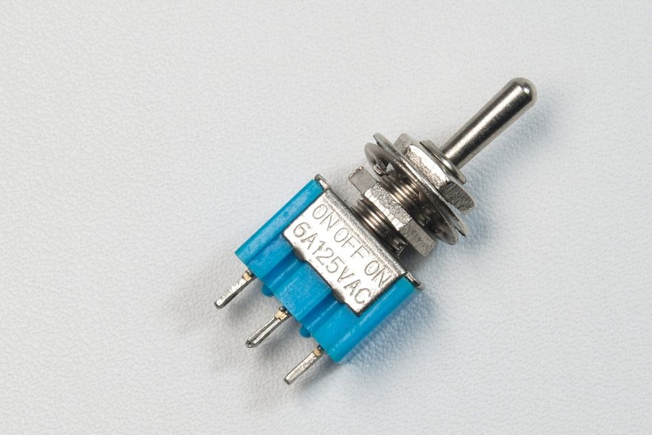
Because SPST switches have only two terminals and one contact state, they are easy to understand and simple to wire. They can be mechanical (toggle, push‑button, rocker or slide) or electronic (MOSFETs configured as on/off switches). The simplicity of the design offers several benefits:
Low cost and easy installation.
Low maintenance because there are few components to fail.
Suitable for basic power control in household appliances, lights or computer power supplies.
Common applications
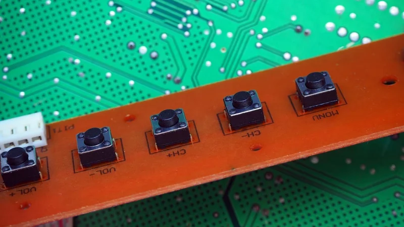
SPST switches are ubiquitous. They appear as light switches in homes, reset buttons on development boards, power controls for consumer electronics, and as simple enabling signals in digital circuits. In control systems, SPST switches can replace two‑wire sensors or serve as safety interlocks. Battery‑powered devices often use SPST switches to connect or disconnect the battery.
Practical example: Microcontroller reset switch
In digital design, microcontrollers typically include a RESET pin that requires a low signal to reset the device. An SPST momentary switch can be wired between the RESET pin and ground (active low).
Pressing the button momentarily pulls the pin low, causing a reset, while releasing the button returns the circuit to its normal state. Debounce circuitry (either RC networks or software debouncing) is often added to ensure clean transitions.

SPDT Switches: Change‑over capability with one pole
Theory of operation
An SPDT switch improves on SPST by adding a second throw. It still controls a single circuit but can connect the common terminal (C) to either a normally‑open (NO) or normally‑closed (NC) terminal. Mechanically, SPDT switches often have a toggle or rocker that redirects current flow between the two terminals. Many SPDTs include a centre‑off position, giving a three‑position ON‑OFF‑ON functionality.
The change‑over configuration enables creative circuit designs:
Switching between two power sources. For example, a portable device can switch between battery and external power by routing the common terminal to the appropriate throw.
Reversing polarity. By swapping positive and negative connections to a small DC motor, an SPDT switch allows the motor to change direction. This concept forms the basis of H‑bridge circuits and direction control modules.
Signal routing. In audio mixers or instrumentation, SPDT switches select between two signal paths or measurement ranges.
Mechanics and benefits
SPDT switches have three terminals—C, NO, and NC. Toggling the switch connects the common terminal to either throw, enabling two separate circuit states. The configuration is widely available in toggle, rocker, slide, and micro‑switch form factors. Key benefits include:
Versatility. SPDT switches allow switching between two different circuits or positions.
Compact design. They provide change‑over capability without requiring additional components.
Energy efficiency. The ability to select between two states reduces the need for extra wiring or logic, saving power in some applications.
Applications
Common uses for SPDT switches include:
Change‑over in electronics: toggling between two circuits or devices.
Reversing DC motors: many hobbyist robots use SPDT switches to change motor direction (when combined in pairs to create an H‑bridge).
Selecting between audio or sensor inputs: measurement devices may route signals to different processing paths.
Power‑source selection: portable electronics can connect to either a battery or an external supply with an SPDT change‑over.
Implementation example: Two‑position selector in digital logic
A practical digital example is building a 2‑to‑1 multiplexer using an SPDT switch. Suppose an FPGA has two configuration modes—normal operation and bootloader. By wiring the common terminal to the microcontroller’s mode select input, the NO terminal to VCC and the NC terminal to ground, the switch selects between logic high and logic low. A centre‑off SPDT could also provide a third state, leaving the pin floating (tri‑stated) or entering a special debugging mode.
When using SPDT switches in digital designs, engineers should consider debounce filtering, either with RC circuits or digital filters, and ensure the contact ratings meet the voltage and current requirements of the logic levels.
Recommended Reading: H Bridge Motor Control: A Complete Guide for Engineers 2025
DPDT Switches: Two poles, two throws
Theory of operation
A DPDT switch is effectively two SPDT switches actuated together. It has two poles—two separate circuits—and two throws for each pole. Internally, the DPDT contains six terminals: two common (C), two normally‑open (NO) and two normally‑closed (NC). When the actuator is toggled, both poles simultaneously switch their common terminals between the respective NO and NC terminals. This arrangement allows designers to control two independent circuits with one lever.
DPDT switches are often used for:
Reversing polarity in DC motors. By wiring the motor leads through a DPDT switch in a cross‑connected pattern, toggling the switch reverses the polarity applied to the motor terminals, causing it to spin in the opposite direction.
Redundant signalling or fail‑over circuits. Two independent signals can be switched simultaneously, providing a main and backup path.
Complex audio routing. Stereo signals can be directed to different outputs or effects chains.
Cross‑bar selection in instrumentation. DPDT switches route two measurement channels concurrently.
Mechanics and benefits
DPDT switches operate as two SPDT circuits in tandem, controlled by a common lever or button. Key advantages include:
Dual‑circuit control: They can switch two separate circuits at once, providing synchronous control or redundancy.
Versatility: With two poles and two throws, DPDT switches enable complex switching and routing, such as reversing motor direction or switching between multiple sources.
Robustness: DPDT switches are typically designed for higher current and power handling, making them suitable for motor control or mains‑voltage circuits.
Applications
DPDT switches appear in many applications:
Motor controllers: reversing a DC motor’s rotation requires swapping polarity on both terminals, easily accomplished with a DPDT wired as an H‑bridge.
Audio and instrumentation: stereo channels can be switched together, ensuring left and right signals maintain proper alignment.
Redundant power switching: DPDT switches can select between two power rails while maintaining isolation between circuits.
Complex lighting systems: multi‑way lighting circuits often use DPDTs to connect two circuits or modes simultaneously.
Implementation example: DC motor direction control
A typical DPDT wiring for motor reversal crosses the wires so that in one position the motor terminals are connected directly, and in the other, they are swapped. When the switch is toggled, the polarity across the motor reverses.
This approach offers a low‑cost, manual method for direction control and is widely used in robotics, small appliances, and lab equipment.
Comparison of SPST, SPDT, and DPDT
The following table summarises the key differences between SPST, SPDT and DPDT switches. Keywords and short phrases are used instead of full sentences to aid readability.
Switch type | Poles × throws | Terminals | Typical states | Applications |
SPST | 1 × 1 | Two terminals (C and NO/NC) | ON/OFF | Power switches, reset buttons, simple lights, battery control |
SPDT | 1 × 2 | Three terminals (C, NO, NC) | Two positions (+ optional centre off) | Change‑over circuits, power source selection, motor direction, selector switches |
DPDT | 2 × 2 | Six terminals (2 × C, 2 × NO, 2 × NC) | Two positions; two circuits switched simultaneously | Motor reversal, redundant signalling, stereo audio routing |
Selecting the right switch
Choosing between SPST, SPDT and DPDT involves more than simply counting poles and throws. The following factors should guide your decision:
Number of circuits to be controlled. SPST is sufficient for a single on/off circuit, while SPDT or DPDT are needed when multiple outputs or simultaneous circuits are involved.
Desired states. Consider whether you need on/off only, change‑over between two outputs, or simultaneous switching of two circuits.
Contact ratings. Voltage and current ratings must meet or exceed your circuit requirements. Exceeding ratings can cause overheating or failure.
Default state and actuation type. Determine whether the switch should be momentary or maintained, and whether it should be normally open or normally closed.
Size and mounting. Switches come in through‑hole, surface‑mount, panel‑mount and DIN‑rail options; choose a format suitable for your mechanical design.
Environmental factors. Industrial applications may demand IP‑rated housings, vibration resistance or vandal‑proof designs.
Suggested Reading: Types of Switches: Complete Engineering Guide for 2025
Practical Considerations when Designing with Switches
Debouncing and signal integrity
Mechanical switches suffer from contact bounce, where the contacts rapidly open and close before settling. In digital circuits, this can cause multiple unwanted transitions. Debouncing can be implemented in hardware (RC networks or Schmitt triggers) or in software (filtering input events). For high‑speed applications or where clean edges are critical, solid‑state switches or relays may be preferable.
Electronic vs mechanical switches
Mechanical switches provide tactile feedback and are easy to integrate, but they wear out over time and cannot switch at very high frequencies. Electronic switches (such as MOSFETs, BJTs or analog multiplexers) offer higher speed, reliability and lower power consumption.
For example, the 74HC4053 is a triple SPDT analog switch that performs signal routing without moving parts. In digital design, electronic switches can implement multiplexers, demultiplexers and tri‑state buffers.
Protection and safety
Selecting a switch with inadequate ratings or poor quality can lead to system malfunction or hazards. Problems include unreliable performance, increased wear, or short circuits and fires.
Always ensure the switch’s voltage and current ratings exceed the worst‑case conditions of your circuit. In high‑energy environments, consider using arc suppression circuits and snubbers to protect contacts from inductive voltage spikes.
Standards and certifications
Industrial applications often require compliance with standards such as UL, IEC or EN for safety and reliability. Look for switches certified for hazardous environments (explosion‑proof or intrinsically safe), and check ingress protection (IP) ratings for dust and water resistance. Engineers designing equipment for regulated industries (medical, aerospace, automotive) must choose components that meet stringent quality and safety requirements.
Recommended Reading: Whats The Difference Between UL And IEC Standards?
Integration of Switches in Digital Design and Hardware Systems
Switches in DigitalLogic Systems
Switches form the front‑end user interface of many digital systems. On microcontroller boards, SPST or SPDT switches select modes, reset the system or trigger interrupts. SPDT switches can implement small multiplexers or select between memory banks, while DPDT switches can route differential pairs or provide manual overrides in system controllers. When connecting mechanical switches to microcontrollers, it is important to:
Debounce the input using RC filters or digital algorithms.
Use pull‑up or pull‑down resistors to define a default logic state when the switch is open.
Protect inputs from voltage spikes or ESD using transient‑voltage‑suppression diodes or RC snubbers.
Analogue signal switching
SPST and SPDT switches can route analogue signals between sensors, amplifiers and ADCs. DPDT switches allow simultaneous switching of differential signals (e.g., balanced audio or differential sensor outputs) without introducing mismatches.
When using mechanical switches for analogue signals, designers must consider contact resistance, signal integrity, and noise. Solid‑state analog switches provide lower on‑resistance and faster switching, but may have higher leakage or limited voltage ranges.
Mechanical switches in power electronics
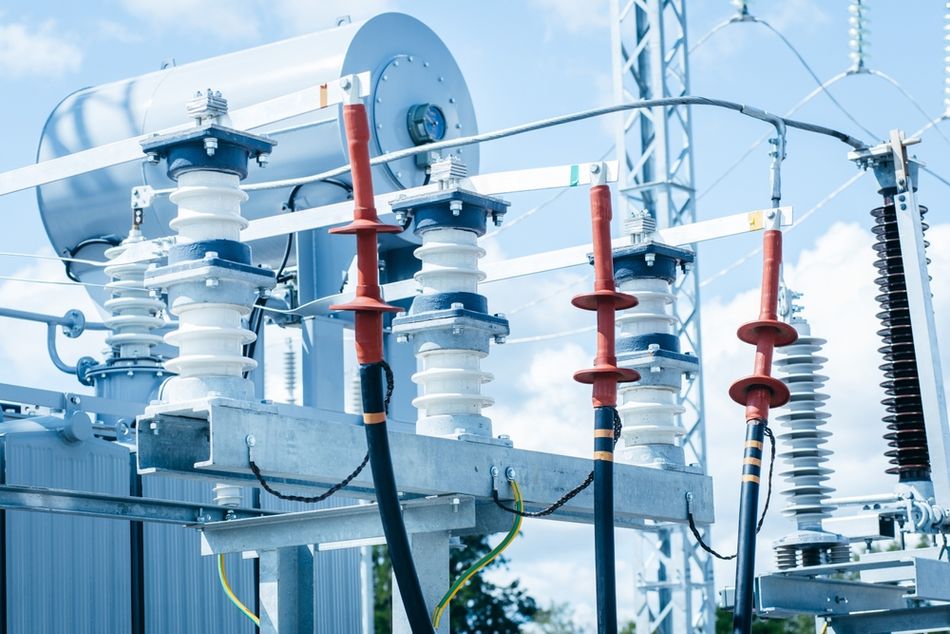
In power electronics, SPST and DPST switches often control mains voltage or high‑power DC circuits. DPDT switches can serve as manual transfer switches, selecting between mains and generator power while maintaining isolation.
For motor control, DPDT switches help implement simple H‑bridge circuits for reversing direction. Engineers must ensure the creepage and clearance distances, contact material and housing all meet regulatory requirements.
Emerging technologies and future trends
Switch technology continues to evolve beyond the classic SPST, SPDT and DPDT. As noted in a 2025 engineering guide, new categories include MEMS switches for RF applications, optical switches for fibre‑optic systems, smart switches integrated with wireless protocols for IoT devices, and GaN or SiC switches operating at higher voltages and frequencies. Spintronic switches leverage electron spin for ultra‑low power memory and logic.
Additionally, there is growing interest in solid‑state relays (SSR) that combine electronic switching with optical isolation for high‑reliability operation. These alternatives provide faster switching, longer life and remote control capabilities, though they may have higher cost or different failure modes compared to mechanical switches.
Recommended Reading: Where GaN can, it should, and GaN can in more and more places
Conclusion
Understanding the difference between SPST, SPDT and DPDT switches is fundamental to designing reliable electronic systems. SPST switches offer simple on/off control for single circuits, SPDT switches provide a change‑over capability to select between two circuits, and DPDT switches switch two circuits simultaneously for more complex applications like motor control. Proper selection requires evaluating circuit requirements, contact ratings, actuation type and environmental conditions. Ignoring these factors can lead to malfunctions and safety hazards.
For digital design engineers, hardware engineers and electronics students, these concepts are more than just acronyms; they define how systems behave. By mastering switch theory and selection criteria, you can design circuits that are safe, efficient and robust, and be prepared to adopt emerging technologies that will shape the next generation of electronic switching.
FAQs
1. What do SPST, SPDT and DPDT stand for?
SPST stands for Single‑Pole Single‑Throw—a switch with one pole and one throw that simply connects or disconnects a single circuit.
SPDT stands for Single‑Pole Double‑Throw—it controls one circuit but can connect the common terminal to either of two outputs.
DPDT stands for Double‑Pole Double‑Throw—it contains two SPDT circuits actuated together, allowing two circuits to be switched simultaneously.
2. How do I choose between SPST and SPDT?
Choose SPST when you only need to turn a circuit on or off. Use SPDT when you need to select between two circuits, such as switching between battery and external power, or reversing the direction of a motor. Consider the desired number of states, required terminals and whether you need a center-off position.
3. Can an SPDT switch mimic an SPST?
Yes. By leaving one throw unconnected or wiring both throws together, an SPDT switch can function as an SPST. This is sometimes done when SPDT switches are more readily available or to provide future expandability.
4. What is the difference between DPDT and DPST?
Both are double‑pole switches, meaning they control two circuits. DPST (Double‑Pole Single‑Throw) only turns both circuits on or off simultaneously, while DPDT allows two throws for each pole, enabling more complex routing, polarity reversal or selection between two states for both circuits.
5. How do I wire a DPDT switch to reverse a DC motor?
Connect the motor terminals to the two centre (common) terminals of the DPDT. Cross the polarity of the supply leads between the two throws: in one position, the positive supply connects to one motor terminal and negative to the other; in the other position, the connections are swapped. This wiring reverses the voltage across the motor, causing it to spin in the opposite direction. Remember to consider current ratings and provide protection against back‑EMF with diodes or snubbers.
6. Are there electronic alternatives to mechanical SPST/SPDT/DPDT switches?
Yes. Electronic alternatives include transistors and MOSFETs configured as on/off switches, analog multiplexers (e.g., 74HC4053) that act as SPDT switches in IC form, and solid‑state relays that combine electronic switching with optical isolation. These devices offer faster switching, longer life and no mechanical bounce but may have different voltage drops or leakage currents.
7. What happens if I choose a switch with an insufficient rating?
Using a switch that is not rated for the voltage or current in your circuit can cause system malfunctions, increased wear and tear, or safety hazards such as overheating and fires. Always select switches with ratings that exceed the maximum expected voltage and current and consider derating for safety.
References
[1] Moniteur Devices, “What is the Difference Between SPST, SPDT and DPDT?,” Moniteur Devices. [Online]. Available: https://moniteurdevices.com
[2] Process Instrument Solutions, “What’s the difference between SPST, SPDT and DPDT?,” Process Instrument Solutions, Feb. 13, 2025. [Online]. Available: https://processinstrumentsolutions.co.uk
[3] Same Sky Devices, “Fundamentals of Switches: A Guide to Types, Uses, and Selection,” Same Sky Devices. [Online]. Available: https://sameskydevices.com
[4] Bituoelec, “Difference Between SPST, SPDT and DPDT Switches,” Bituoelec. [Online]. Available: https://bituoelec.com
in this article
1. Introduction2. Fundamentals of Switches: Poles, Throws, and Contact States3. SPST Switches: The simplest on/off control4. SPDT Switches: Change‑over capability with one pole5. DPDT Switches: Two poles, two throws6. Comparison of SPST, SPDT, and DPDT7. Practical Considerations when Designing with Switches8. Integration of Switches in Digital Design and Hardware Systems9. Emerging technologies and future trends10. Conclusion11. FAQs12. References