What is a Relay? Theory, Types, and Practical Implementation for Engineers
Relays are the unsung heroes behind automated power control. This indepth guide discusses what is a relay for digital design and hardware engineers. It explains how relays work, compares electromechanical and solid state designs, and provides design tips and application examples.

16 Feb, 2026. 14 minutes read
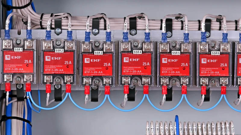
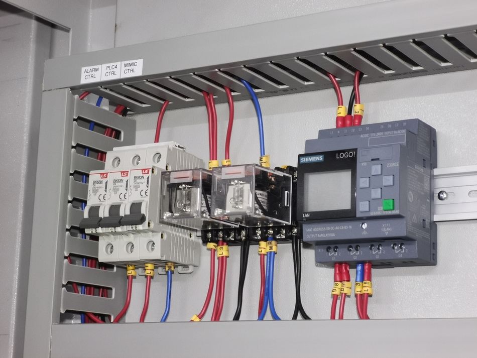
Array of Single-Phase Solid State Relays mounted on an Industrial Control Panel
What is a Relay? Theory, Types, and Practical Implementation for Engineers
Relays are the unsung heroes behind automated power control. This in‑depth guide discusses what is a relay? for digital design and hardware engineers. It explains how relays work, compares electromechanical and solid‑state designs, and provides design tips and application examples.
Key takeaways
A relay is an electrically operated switch that isolates circuits and allows low‑power control of high‑power loads.
Relays comprise a coil, a movable armature, and contacts. Poles, throws, and forms define how many circuits they control and how many positions are available.
Electromechanical relays (EMR) use an electromagnet to drive contacts; solid‑state relays (SSR) employ semiconductor devices, providing faster switching and much longer life.
Selecting a relay involves considering coil voltage/current, contact ratings, switching speed, life expectancy, and suppression circuits to mitigate arcing and bounce.
Relays serve countless applications from power protection and automation to automotive electronics and digital design. Advances such as reed, latching, and hybrid relays further extend their capabilities.
Introduction
Control and actuation are the outputs in most electronic circuits, whether it’s the power industry, embedded systems, digital design, or robotics. So, if you’re wondering, “What is a relay?”, it’s the device that turns those control signals into a meaningful action. A relay is an electrically operated switch that opens and closes circuits in response to a small control signal. Instead of manually toggling contacts, a relay receives an electrical input and transfers that signal to another circuit by switching its contacts. This ability to isolate circuits and control high‑power loads with low‑power signals makes relays indispensable in automation, protection systems, communication equipment, and embedded hardware.
Without relays, microcontrollers would struggle to control motors, lighting, or heaters. In this article, you will learn the underlying theory of relays, explore key terminologies such as poles, throws, and contact forms, compare major relay types, and discover practical design considerations. By the end, you will understand how to choose and implement relays effectively in your projects.
Relay Basics and Theory
Definition and purpose
A relay is an electrically operated switch used to isolate circuits, switch between circuits, and control a high‑power circuit with a low‑power signal. In a typical scenario, a microcontroller or digital logic circuit energizes the relay’s coil. The resulting magnetic field moves an armature that opens or closes contacts, thereby connecting or disconnecting the power circuit.
This isolation protects delicate electronics from high voltage or current surges and enables automatic control of equipment. Relays are essential in protection systems, lighting control, computer interfaces, motors, telecommunication and countless other applications.
Construction and Components
Most electromechanical relays share a common structure with four terminals:
Control input (coil terminals): two terminals connected to the low‑power circuit that energize the coil.
Common (COM): the movable contact output connected to the load circuit.
Normally open (NO): remains disconnected from the common contact until the relay is energized.
Normally closed (NC): remains connected to the common contact in the unenergized state and opens when the relay activates.
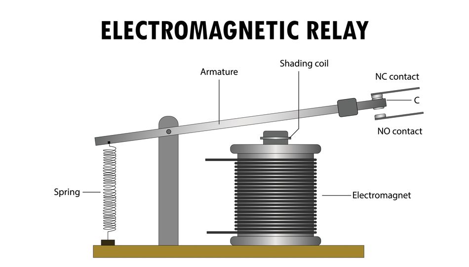
Inside the relay, an iron core surrounds the coil. When electrical current flows through the coil, it creates a magnetic field that magnetizes the iron core and pulls the armature. The armature pivots to bridge or separate the contacts, thereby switching the load circuit.
Operating principle
Relays operate using electromagnetic induction. When the control circuit energizes the coil, current generates a magnetic field that magnetizes the iron core and pulls the armature toward it. The armature’s movement changes the contact states: it closes the normally open circuit and opens the normally closed circuit.
When the coil is de‑energized, a spring returns the armature to its default position. The time between coil activation and contact change is called the operate time and typically ranges from a few to tens of milliseconds for mechanical relays.
Suggested Reading: Open Circuit vs Short Circuit: Core Differences between Open and Closed Circuit
Poles, Throws, and Forms
Relays are described using the number of poles (independent circuits they switch) and throws (positions each pole can connect to).
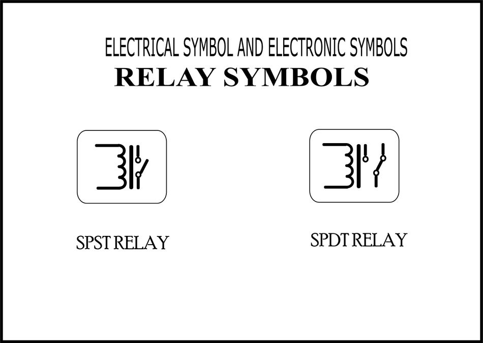
A single‑pole single‑throw (SPST) relay has one pole and one throw; it simply connects or disconnects a single circuit.
A single‑pole double‑throw (SPDT) relay has one pole and two throws; it can connect the common terminal to either the normally closed or normally open contact.
Double‑pole relays replicate these functions on two independent circuits. Table 1 summarises the main contact forms.
Relay form | Description | Use cases |
SPST (Form A) | Single pole, single throw. Contact is normally open and closes when energized. Also called Form A contact. | Simple on/off control, LED switching. |
SPST (Form B) | Single pole, single throw. Contact is normally closed and opens when energized (Form B). | Safety circuits that should remain energized unless triggered. |
SPDT (Form C) | Single pole, double throw. Switches a single circuit between two positions; commonly referred to as a Form C relay. | Selecting between two loads; toggling signals. |
DPST/DPDT | Double pole, single throw/double throw. Switches two circuits simultaneously; DPDT is equivalent to two Form C contacts driven by one coil. | Power distribution, reversing motor direction, stereo audio switching. |
Multiple Form C contacts can be combined in a single relay to control more circuits, but increasing the number of poles beyond two can decrease reliability and is seldom used.
Recommended Reading: What Is the Difference Between SPST, SPDT and DPDT? A Comprehensive Guide for Engineers
Actuator and Actuator Power
The coil is specified by its voltage and current requirements. For example, a 5 V relay may require approximately 70 mA of coil current to actuate. A digital output or microcontroller may not supply enough current, so engineers often use a transistor or MOSFET drivers to energize the coil.
Because relay coils are highly inductive loads, removing power causes the magnetic field to collapse and generate a high back electromotive force (EMF). A reverse‑biased diode across the coil (flyback or free‑wheel diode) safely dissipates this energy and prevents damage to the switching transistor.
Contact Bounce and Arcing
Mechanical relays exhibit contact bounce when their contacts physically vibrate as they close. This can cause multiple rapid on/off pulses in the output electrical signal. While harmless in power circuits, contact bounce can cause false triggers in digital logic or audio artifacts. Solid‑state relays do not suffer from bounce.
Mechanical relays also experience arcing when contacts open or close under load; arcs generate noise and heat that erode the contact surfaces and may weld them together. To mitigate arcing, designers use RC snubber networks, metal oxide varistors or varistor diodes across the contacts, or implement solid‑state relays for high‑frequency or inductive loads.
Types of Relays
Relays can be classified by their contact arrangement, operation principle, and application. Understanding these categories helps engineers select the right component.
Electromechanical Relays
Electromechanical relays use a magnetic coil to move mechanical contacts. They are versatile, inexpensive, and can switch AC or DC loads. However, their moving parts limit switching speed and life expectancy.
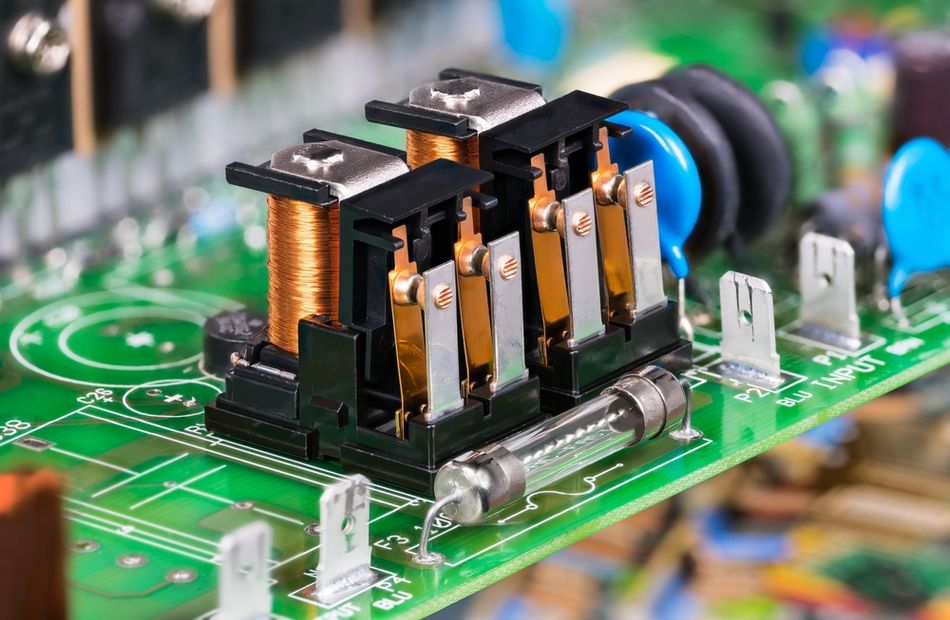
Electromechanical relays rely on a coil that pulls an armature and creates a magnetic field; the main drawback is contact arcing, which reduces lifespan over time. EMRs typically achieve lifetimes around one million cycles, though actual life depends on the load and environment. Operating times for EMRs are on the order of tens of milliseconds.
Advantages | Disadvantage |
|
|
Solid‑State Relays (SSR)
Solid‑state relays replace mechanical contacts with semiconductor devices such as triacs, thyristors or MOSFETs. An optocoupler provides isolation between the input and output. When the input LED is driven, it activates a photodiode array or photo‑triac which triggers the power semiconductor and switches the load. SSRs switch quickly (typically 1 ms), have no moving parts, and are immune to contact bounce.
Typically, solid‑state relays can last roughly 100 times longer than electromechanical relays and are less sensitive to shock, vibration, and external magnetic fields.
Advantages | Disadvantages |
|
|
Suggested Reading: Solid-State Relays: Bringing Robustness to High-Cycle Switching Applications
Reed Relays
Reed relays combine a reed switch and an electromagnetic coil. A reed switch contains two ferromagnetic metal blades (reeds) sealed in a glass tube filled with an inert gas. Energizing the coil pulls the blades together, closing the circuit. Because the contacts are hermetically sealed, reed relays exhibit very low contact resistance and extremely long life (hundreds of millions of operations).
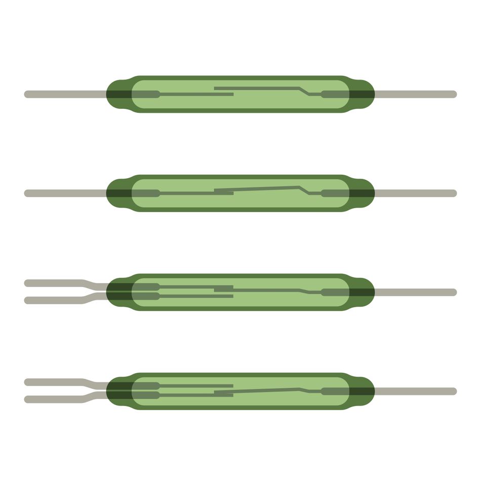
Reed relays eliminate moving armatures, making them faster and reducing wear. However, Reed relays handle lower currents than EMRs and are susceptible to shock. Typical switching times are on the order of 0.1 ms.
MOSFET and photoMOS relays
MOSFET relays, sometimes called photoMOS relays, use a combination of LED, photodiode array, and power MOSFETs to create a semiconductor switch. A MOS FET relay comprises an LED chip, a photodiode array, and a MOSFET chip.
When the LED is energized, the photodiode array generates a gate voltage that turns on the MOSFET, providing isolation and switching. These relays combine the advantages of Solid State Relays (fast, silent switching) with low leakage current and can switch both AC and DC loads.
Suggested Reading: Optimizing PCB Space and System Reliability with OMRONs G3VM Solid-State MOS FET Relays
Latching relays
A latching relay maintains its state without continuous coil power. After receiving a set pulse to change state, it uses a permanent magnet or magnetic latch to hold the contacts. A second pulse resets the relay. Latching relays are useful in low‑power or battery‑powered systems because they consume energy only during state changes.
Some latching relays use two coils (set and reset), while others rely on magnetic polarization. Magnetic latching relays are triggered by a short pulse and remain triggered until another pulse causes them to release.
Hybrid Relays
Hybrid relays combine electromechanical and solid‑state elements. One common design uses an SSR to turn on quickly and handle inrush current, then an EMR contact closes to reduce on‑state power dissipation.
This hybrid approach leverages the fast switching and long life of SSRs with the low on‑resistance and current handling capabilities of EMRs. Hybrid relays are useful in motor drives and lighting control, where both speed and efficiency are critical.
Time‑Delay and Protective Relays
Time‑delay relays introduce on‑delay, off‑delay or cyclic timing between input and output. They are used in sequential control and automation. Protective relays detect abnormal conditions (over‑current, under‑voltage, frequency errors) and trigger circuit breakers or alarms to prevent damage.
Protection relays monitor electrical parameters, compare them with thresholds and isolate faulty sections to protect equipment. Voltage relays, current relays, thermal relays, and magnetic relays fall into this category.
Recommended Reading: How Do Time Delay Relays Work?
Practical Design Considerations
Selecting and integrating a relay into a circuit involves careful evaluation of electrical characteristics, environmental factors and mechanical constraints.
Coil voltage and current
Relays are available with coil voltages ranging from a few volts to hundreds of volts. The control circuit must supply the rated coil voltage and sufficient current to energize the relay; otherwise the magnetic field will be insufficient to operate the armature.
For example, a typical 5 V mechanical relay may draw around 70 mA. To drive such a relay from a microcontroller, use a transistor or MOSFET with a flyback diode across the coil.
Contact Ratings and Load Type
Contact ratings specify the maximum current and voltage the relay can safely switch. For AC loads, ratings may be higher than for DC loads because AC zero‑crossing reduces arcing. The contact material affects durability; silver alloys offer low resistance, while gold‑plated contacts suit low‑level signals.
As a designer, you should avoid connecting relay contacts in parallel to share current because the contacts never close or open simultaneously, leading to overload and premature failure. Instead, choose a relay with a single contact rated for the full load or use multiple relays. Mix loads of different voltage levels only with separate relays for safety.
When switching inductive loads (motors, transformers), use snubber circuits or MOVs across the contacts to suppress voltage spikes. For DC inductive loads, a diode across the load or coil is an effective solution.
Switching Speed and Frequency
Mechanical relays switch in tens of milliseconds, making them unsuitable for high‑frequency applications requiring rapid toggling. They also generate heat and may overheat if switched too frequently.
Solid‑state relays achieve switching times around 1 ms and support rapid cycling but require proper thermal management. Reed relays bridge the gap, offering sub‑millisecond switching for low‑current applications. When timing and frequency are critical, SSRs or reed relays are often the best choice.
Mechanical Life and Reliability
Mechanical wear limits the life of electromechanical relays. Manufacturers often specify mechanical life between 100000 and 1000000 operations. Contact wear results from friction, arcing and metal migration. Reed relays are hermetically sealed and can last hundreds of millions of cycles.
Solid‑state relays have life expectancies up to hundreds of millions of cycles. Research indicates that coil durability is about 40 000 hours of continuous operation, and contact durability depends on the load and must be determined from durability curves.
Use dedicated relay sockets to simplify maintenance and replacement; they allow relays to be swapped without soldering and reduce the risk of printed circuit board damage. Inspect mechanical relays periodically for signs of pitting or discoloration on contacts, and replace them when reliability is critical. For long‑life applications, consider SSRs or reed relays.
Contact Bounce Mitigation and Debouncing
Contact bounce can cause multiple triggers. Designers implement hardware debouncing using RC networks or Schmitt triggers, or software debouncing, where microcontrollers ignore transitions occurring within a specified time after a contact closure.
For low‑speed power switching, bounce is often negligible. When switching digital signals or audio, SSRs or reed relays provide bounce‑free operation.
Safety and Failure Modes
Relays handle dangerous voltages and currents. Always place a relay between the power supply and the load to ensure that the load is isolated when the relay is open. Mechanical relays may fail “closed” due to contact welding.
To mitigate risks, incorporate safety interlocks such as thermal fuses, current sensors or secondary cut‑offs. When designing control circuits, choose normally open or normally closed contacts based on the desired fail‑safe behaviour.
Applications of Relays
Relays are ubiquitous across industries. Their ability to isolate circuits and switch high‑power loads enables many applications.
Power Control and Automation
In industrial automation, relays control motors, pumps, lights and heating elements. They interface between programmable logic controllers (PLCs) or microcontrollers and large loads. For example, solid‑state relays provide rapid, silent switching in temperature‑controlled ovens or reflow soldering systems where the mains supply must be cycled every few seconds.
Electromechanical contactors—high‑current relays—start and stop electric motors in HVAC units, elevators and conveyors.
Suggested Reading: Contactor vs Relay: Understanding the Differences and Applications
Protection and Safety Systems
Protection relays monitor electrical parameters such as current, voltage and frequency to detect abnormal conditions. Upon detecting an overload, short circuit or under‑voltage, they trip circuit breakers or send alarms.
Voltage relays and current relays protect sensitive equipment from surges and spikes. Thermal relays provide over‑temperature protection for motors and transformers by sensing heating and disconnecting the supply.
Automotive and Transportation
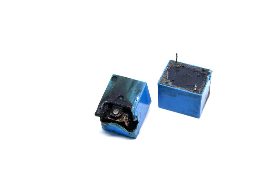
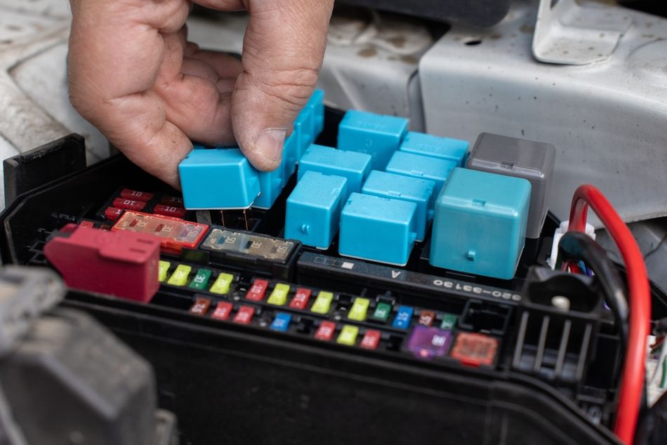
Automotive systems rely heavily on relays: headlamps, horns, windshield wipers, starter motors and fuel pumps are often controlled through electromechanical relays. Automotive relays must withstand vibration and temperature extremes and are designed with sealed or hermetic enclosures. Latching relays help manage battery loads by maintaining state without continuous power.
Home automation and IoT
Relays enable smart home devices to control lighting, appliances and security systems. Wi‑Fi or Bluetooth modules send control signals to relay boards, which switch mains power.
Solid‑state relays are common in smart dimmers because they permit zero‑cross switching and quiet operation. Latching relays reduce energy consumption in battery‑powered IoT sensors.
Medical and aerospace
Medical devices, laboratory equipment and aerospace systems demand high reliability and isolation. Reed relays and solid‑state relays provide low leakage currents, long life and resistance to shock and vibration, making them suitable for ECG monitors, MRI machines, flight controls and satellite communication.
Emerging Trends and Future Directions
The relay market continues to evolve with new materials, integration methods and smart features:
MEMS and micro‑relays: Micro‑electromechanical relays integrate moving contacts on a silicon substrate. They offer very low on‑resistance and can operate at microwave frequencies. MEMS relays are promising for RF switching and space‑constrained applications.
Smart relays: Modern relays incorporate microcontrollers and sensors to monitor load current, temperature, and contact wear. They can provide predictive maintenance alerts, remote diagnostics, and communication interfaces.
Wide‑bandgap devices: Using wide‑bandgap semiconductors such as gallium nitride (GaN) and silicon carbide (SiC) in SSRs improves efficiency and thermal performance, enabling compact high‑power relays.
Environmentally robust relays: New sealing techniques and materials improve resistance to moisture, dust, and corrosive atmospheres, extending reliability in automotive and industrial environments.
Conclusion
Relays are critical components for isolating and switching circuits. At their core, they answer the question “what is a relay?” by providing an electrically operated switch that transfers control signals from low‑power circuits to high‑power loads. Understanding the theory behind coils, armatures, poles, and throws enables engineers to select the right relay form—SPST, SPDT, DPST, or DPDT—for a given application. Electromechanical relays offer cost‑effective, flexible switching but are limited by mechanical wear and switching speed. Solid‑state relays deliver silent, fast, and long‑lasting performance at the expense of higher voltage drop and heat. Reed, MOSFET, latching, and hybrid relays fill specialized niches, while protective and time‑delay relays guard against overloads and coordinate sequences.
Designers must account for coil voltage, contact ratings, load type, switching frequency, mechanical life, and safety. Proper driver circuits and suppression elements—such as flyback diodes, snubbers, and MOVs—protect both relay and control circuitry. When implemented correctly, relays enable robust control solutions across industries, including automation, automotive, telecommunications, IoT, medical, and aerospace.
FAQs
1. What is the difference between a relay and a contactor?
A contactor is a type of high‑power relay designed specifically for switching large currents (typically >10 A) in industrial motors, lighting and heating systems. Contactors are mechanically robust, often include arc extinguishing chambers, and may have auxiliary contacts for control circuits. Standard relays (signal relays) switch lower currents and are more compact but have lower power ratings.
2. When should I choose a solid‑state relay over an electromechanical relay?
Use a solid‑state relay when the application requires fast switching (<1 ms), high cycling frequency, silent operation or extremely long life. SSRs are ideal for temperature control, servo motors and precision instrumentation. Choose electromechanical relays when low on‑resistance, high load currents or cost‑effectiveness are priorities and switching speed is less critical.
3. How do I determine the correct coil voltage for my relay?
Select a relay with a coil voltage that matches your control circuit (e.g., 3.3 V, 5 V, 12 V). Ensure the control circuit can supply the coil’s rated current (often tens of milliamps). If not, use a transistor or MOSFET driver with a flyback diode. Running a relay at a voltage too low may prevent it from activating; too high a voltage may overheat the coil and shorten its life.
4. Why does my mechanical relay create a buzzing sound?
Buzzing often results from an insufficiently filtered DC supply applied to the coil. Ripple voltage can cause the armature to vibrate, accelerating mechanical wear. Ensure the supply is well filtered (peak‑to‑peak ripple <10 % of the supply voltage) or use a regulated supply. Alternatively, switch to a solid‑state relay that is immune to vibration and buzzing.
5. Can I connect relay contacts in parallel to handle higher current?
No. Mechanical relay contacts do not close or open simultaneously; paralleling them may overload one contact and cause premature failure. Instead, use a relay with contacts rated for the desired current or employ multiple relays switching separate loads.
6. What is contact bounce, and how can I mitigate it?
Contact bounce is the rapid closing and opening of contacts when a mechanical relay switches. It produces multiple short pulses that can confuse digital circuits or cause noise in audio lines. Mitigate bounce by using hardware RC filters, Schmitt triggers or software debouncing. Alternatively, use solid‑state or reed relays, which have no contact bounce.
7. How do time‑delay relays differ from standard relays?
Time‑delay relays include timing circuitry that delays the switching action. On‑delay relays wait a set period after receiving an input before closing contacts; off‑delay relays open contacts after a delay. They are used for sequencing events, motor starting, or preventing simultaneous activation of loads. Standard relays switch immediately upon coil activation.
References
OMRON Device & Module Solutions Company, “What is an Electrical Relay?,” components.omron.com, Singapore, Sep. 2025. [Online]. Available: https://components.omron.com/sg-en/products/basic-knowledge/relays/basics
Veris Industries, “What is a Relay? Relay Types, How They Work, & Applications,” veris.com, Dec. 2022. [Online]. Available: https://www.veris.com/blog/relay-types-how-they-work-applications
Tameson, “Relay Types, Operation, and Applications,” tameson.com, Jul. 2025. [Online]. Available: https://tameson.com/pages/types-of-relays
Electronics Tutorials, “Solid State Relay Tutorial,” electronics-tutorials.ws. [Online]. Available: https://www.electronics-tutorials.ws/power/solid-state-relay.html
Phidgets, “Mechanical Relay Guide,” phidgets.com, Nov. 2025. [Online]. Available: https://www.phidgets.com/docs/Mechanical_Relay_Guide