PLC and SCADA: Key Differences and How They Work Together
In this article, we'll see how PLC and SCADA systems differ, how they work together, and which protocols, scan times and security controls matter in industrial automation.

Last updated on 24 Sep, 2026. 16 minutes read
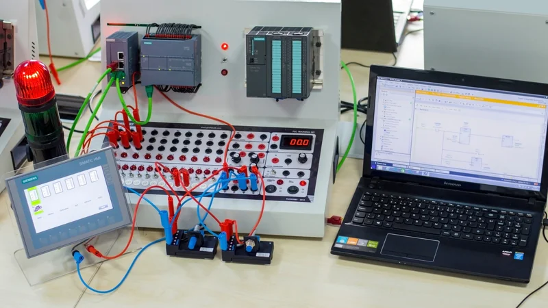
PLC and SCADA, HMI Equipment for Industry 4.0
Key Takeaways
Definition – PLC is a controller, while SCADA is a supervisory layer. They sit at different levels of the same hierarchy, so "PLC vs SCADA" is architecturally inaccurate.
Control Architecture Role – PLCs are the control components inside SCADA and DCS architectures, where they locally manage processes through feedback control.
Scan Cycle Dynamics – PLCs run a fixed scan cycle: read inputs, execute the program, write outputs. On a Siemens S7-1500, the default minimum cycle time is 1 millisecond and the default maximum cycle time is 150 milliseconds.
Geographic and Enterprise Scale – SCADA earns its place when assets are geographically dispersed, and centralized data acquisition matters as much as control.
Communication Security Vulnerabilities – Several protocols that bridge the two layers, including Modbus and unencrypted DNP3, carry no built-in authentication or encryption.
Introduction
PLC and SCADA are fundamental components of industrial automation, helping operators control equipment, monitor processes, and maintain visibility across production environments. PLCs execute control logic close to the process, while SCADA provides broader operational oversight.
Understanding PLC and SCADA begins with separating direct machine control from supervisory monitoring. PLCs read sensor inputs, process programmed instructions, and command actuators. SCADA systems collect data from controllers, display process conditions, manage alarms, and support historical analysis. Together, PLC and SCADA connect automated actions with the information operators need to manage plant performance.
In this article, we'll see how PLC and SCADA systems differ, how they work together, and which protocols, scan times and security controls matter in industrial automation.
What a PLC Actually Does?
Programmable Logic Controller (PLC) is a solid-state control system with user-programmable memory for storing instructions and implementing functions such as I/O control, logic, timing, counting, three-mode (PID) control, communication, arithmetic, and data and file processing. [1]
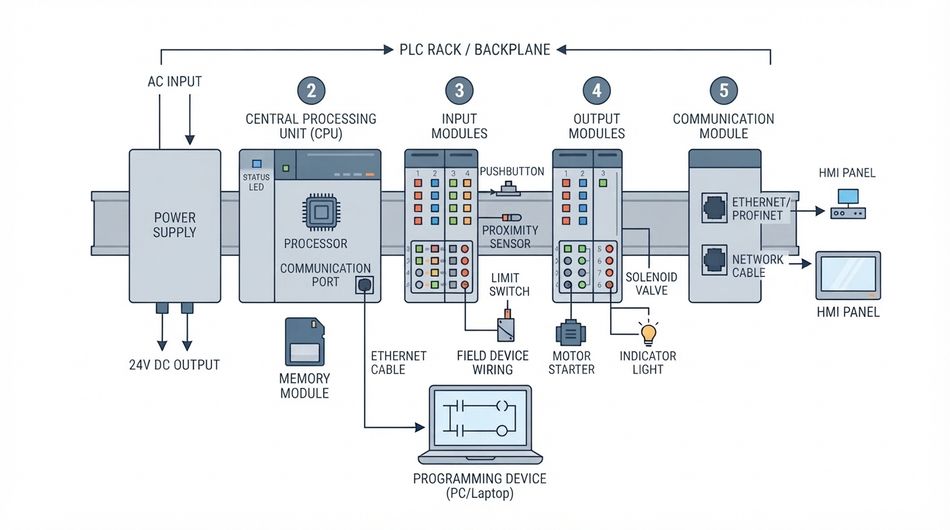
That definition is worth reading slowly because it lists what a PLC does on its own, without a control room, an operator, or a network.
PLCs are the control components of a larger hierarchical system, managing processes locally through feedback control. They drive field actuators such as motors, valves and heaters. [6] In control, a relay is an electromechanical device that completes or interrupts a circuit by physically moving conductive contacts, and that motion can be coupled to a valve or breaker.
The same programmable memory holds the timers and counters that sequence a machine, so a PLC needs no external logic to run a process.
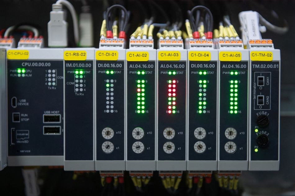
Critically, a PLC can also be the whole system. PLCs are implemented as the primary controller in smaller configurations to control discrete processes such as automobile assembly lines. [1] These topologies differ from SCADA and DCS in that they generally lack a central control server or HMI, so they provide closed-loop control with minimal human involvement.
If your process is one machine and nobody needs a plant-wide view, a PLC alone is a complete automation solution.
The Scan Cycle Is the Defining Constraint
PLCs are deterministic real-time controllers that scan inputs, execute control logic, and update outputs on millisecond cycles. [6] That loop is the single most important thing to understand about PLC behavior.
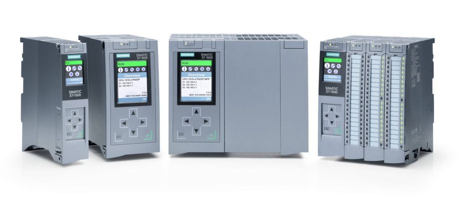
Siemens documents the SIMATIC S7-1500 cycle in three phases: update the input process image partition, process the cyclic program, then update the output process image partition. [5] In hardware terms, the CPU reads the input status at the input module and writes it to the input process image, processes the user program, then writes the output states from the process image to the output modules.
Cycle Time is the time the CPU needs to execute the cyclic program, update the process image of inputs and outputs, and handle all program parts and system activities that interrupt the cycle.
Here, two numbers matter for design:
Minimum Cycle Time: In STEP 7, you can set a minimum cycle time for the CPU, and the default is one millisecond. Raising it reduces cycle-time fluctuations and frees computing time for communication tasks. [5]
Maximum Cycle Time: The CPU monitors the cycle time; by default, the maximum is 150 milliseconds. If the time error OB (OB 80) is called. If you have not loaded an OB 80, or the cycle still does not complete after an additional maximum cycle time, the CPU goes to STOP. [5]
That watchdog is why an inefficient loop in your control logic does not just slow the process down. It stops the machine. Being deterministic simply means these variations remain strictly bounded. Consequently, the watchdog mechanism ensures that inefficient control logic halts cycle execution and stops machine operation rather than merely causing delays.
Programming Languages: What IEC 61131-3 Now Specifies
PLC programming is standardized in IEC 61131-3, and the standard changed recently in a way many references have not caught up with.
The current edition, IEC 61131-3:2025 (Edition 4.0, published 22 May 2025), specifies the textual language Structured Text (ST), and the graphical languages Ladder Diagram (LD) and Function Block Diagram (FBD). [2] It also defines Sequential Function Chart (SFC) elements for structuring programs.
The previous edition, IEC 61131-3:2013, listed Instruction List (IL) alongside Structured Text as a textual language. [3] IEC withdrew that edition on 22 May 2025. [3] So references that describe five IEC 61131-3 languages, including Instruction List, are describing the superseded edition.
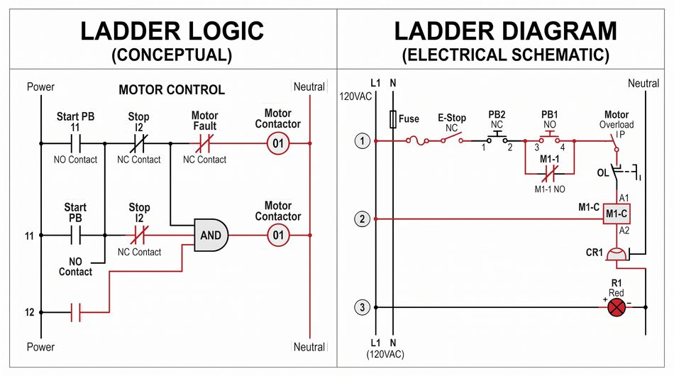
In practice, ladder logic remains widely used for discrete machine control, largely because it reads like the relay schematics maintenance teams already know. Structured text tends to be preferred for arithmetic, loops and anything resembling an algorithm. Both preferences are trade conventions rather than standard requirements.
Recommended Reading: PLC Programming: Languages, Scan Cycles, and Working Ladder Logic
What a SCADA System Actually Does?
SCADA stands for Supervisory Control and Data Acquisition. SCADA systems are used to control dispersed assets where centralized data acquisition is as important as control.
The word "dispersed" does the work there. SCADA systems are used in distribution systems such as water distribution and wastewater collection, oil and natural gas pipelines, electrical utility transmission and distribution, and rail and other public transportation.
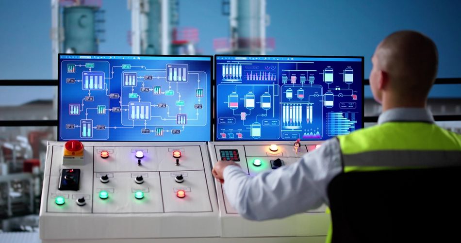
SCADA integrates data acquisition systems with data transmission systems and HMI software to provide centralized monitoring and control for numerous process inputs and outputs. [1] The design intent is to collect field information, transfer it to a control center, and display it to the operator graphically or textually, so the operator can monitor or control an entire system from a central location in near real time.
SCADA System Components
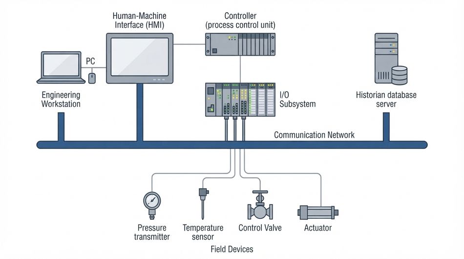
Typical SCADA hardware includes a control server at a control center, communications equipment such as radio, telephone line, cable or satellite, and one or more geographically distributed field sites consisting of remote terminal units (RTUs) and/or PLCs that control actuators and monitor sensors.
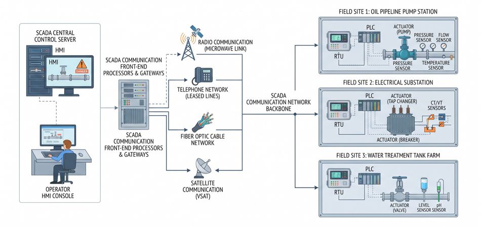
The division of labor is explicit: the control server stores and processes information from RTU inputs and outputs, while the RTU or PLC controls the local process.
RTU is a computer with radio interfacing used in remote situations where wired communication is unavailable, usually to communicate with remote field equipment. PLCs with radio communication capabilities are also used in place of RTUs. [1] That is the clearest statement of why the RTU/PLC distinction has blurred: modern PLCs took over the job.
The academic survey of OT networks describes the same structure in layers: a SCADA system integrates a sensing layer of field instruments, a control layer of programmable controllers, and a supervisory layer comprising the master station, HMI and historian. [6]
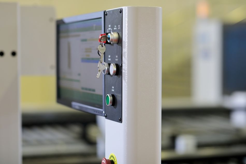
The human-machine interface is the hardware or software through which an operator interacts with a controller, ranging from a physical control panel with buttons and indicator lights to an industrial PC with a color graphics display running dedicated HMI software. HMI provides operators with process visualization, alarm management and command issuance, while historians archive time-stamped process data for trend analysis, regulatory reporting and predictive maintenance. [6]
Historical data is not a nice-to-have on a SCADA platform. Trending and regulatory reporting are among the functions the historian serves.
This layered structure is also what makes SCADA scalable: adding a field site means adding controllers and a communications link, not redesigning the supervisory system. It also puts SCADA at the center of critical infrastructure operations, since the same architecture carries water distribution, pipelines, and electricity transmission.
Suggested Reading: What is SCADA: The Basics You Need to Know
SCADA Is Also Not a DCS
The distributed control system controls production systems within the same geographic location, in industries such as oil refineries, water and wastewater treatment, electric power generation, chemical manufacturing, automotive production and pharmaceutical processing. DCS uses a centralized supervisory control loop to coordinate a group of localized controllers that share the tasks of an entire production process. [1]
The boundary between SCADA and DCS has blurred as both adopt Ethernet-based networking and shared HMI conventions, but the canonical distinction remains: SCADA emphasizes wide-area supervisory data acquisition, while DCS emphasizes localized continuous control with heavy inter-controller communication.
Suggested Reading: What is a Distributed Control System (DCS)?
PLC vs SCADA: The Core Differences
PLC is a solid-state control system with user-programmable memory that manages a local process through logic and feedback control. SCADA system integrates data acquisition, communication, and human-machine interface software to provide centralized monitoring and supervisory control. The PLC directly controls equipment, while SCADA allows operators to observe conditions and issue commands across connected assets.
Their operational scope and timing requirements differ. A PLC typically controls a machine, production cell, or field installation, executing control tasks on millisecond timescales. [6] SCADA commonly connects geographically dispersed assets across a distribution network and presents operational information to control-room personnel in near real time. [1] PLCs can operate independently with minimal human involvement; SCADA relies on field controllers, such as PLCs or RTUs, to execute local control.
The programming and configuration reflect these responsibilities. PLC applications use languages such as Structured Text, Ladder Diagram, and Function Block Diagram, with Sequential Function Chart supporting program organization. [2] SCADA engineering focuses on configuring communication links, tags, operator screens, alarms, and historical data storage.
The impact of failure is another distinction. SCADA outage can remove operator visibility and centralized commands while local controllers continue running the process. [1] PLC failure directly affects the equipment it controls and may interrupt operation or trigger a configured safe state. The outcome depends on redundancy, application design, and how dependent the process is on supervisory commands.
How PLC and SCADA Work Together?
In an integrated system, the SCADA layer polls controllers for process data and writes setpoints back. The pattern includes intelligent electronic devices (IEDs) such as protective relays, which may communicate directly to the control server, or be polled by a local RTU that collects the data and passes it on.
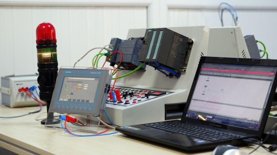
Field Devices in this picture include RTUs, PLCs, actuators, sensors, HMIs and associated communications. [1] Many connect over a fieldbus: a digital, serial, multi-drop, two-way data bus between low-level industrial field equipment such as sensors, transducers, actuators, and local controllers.
Fieldbus Networks eliminate point-to-point wiring between a controller and individual sensors and actuators. They also enable functionality beyond control, including field device diagnostics, and can execute control algorithms within the fieldbus itself, avoiding routing signals back to the PLC for every control operation.
Industrial Communication Protocols
PLC and SCADA systems exchange data through industrial communication protocols that define how devices structure, transmit, and interpret information.
Modbus is an application-layer protocol that uses function codes in a request/reply model. Originally introduced for serial communication in 1979, it also supports Ethernet through Modbus TCP, which uses reserved TCP port 502. [4]
PROFIBUS DP, standardized under IEC 61158, supports RS485 transmission rates from 9,600 bit/s to 12 Mbit/s, with up to 32 nodes per segment. [10]
PROFIBUS PA uses the same communication protocol with a different physical layer. Its Manchester Bus Powered (MBP) transmission operates at a fixed 31.25 kbit/s and supports segment lengths up to 1,900 metres, subject to installation constraints.
DNP3 serves electric utility, energy, and water applications, with implementation subsets accommodating both simple field devices and more capable systems. [8]
OPC UA, standardized through the IEC 62541 series, provides another framework for industrial information exchange.
The Modbus data model is particularly relevant to SCADA tag configuration. It defines four primary tables: discrete inputs are single-bit, read-only values; coils are single-bit, read-write values; input registers are read-only 16-bit words; and holding registers are read-write 16-bit words. Each table supports 65,536 addressable items, numbered from 0 to 65,535 within the protocol data unit (PDU). [4]
Modbus message sizes reflect its serial origins. Modbus RTU application data unit (ADU) can contain up to 256 bytes, including the device address and error-checking field, leaving a maximum PDU of 253 bytes. Modbus TCP adds a seven-byte MBAP header, producing a maximum ADU size of 260 bytes. Individual function codes impose additional limits: Read Coils (function code 0x01) retrieves between 1 and 2,000 contiguous coil states per request. [4]
During commissioning, device-specific register mapping requires careful attention. The protocol defines the data tables, but the manufacturer determines how those addresses correspond to application variables. Identical holding-register addresses on two controllers can represent entirely different measurements or commands.
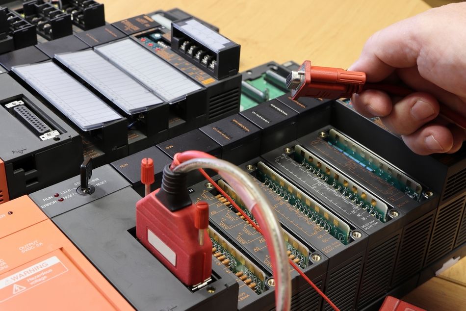
Switching between serial Modbus and Modbus TCP changes message framing, but it does not resolve these mapping differences. Use the relevant device documentation and verify the applicable protocol specification and standards edition before implementation.
Alarm Management Belongs to the Supervisory Layer
PLC can raise a bit. Deciding what an operator should see, and in what priority, is a discipline of its own, covered by ANSI/ISA-18.2-2016, Management of Alarm Systems for the Process Industries. It provides a framework for managing alarm systems across process control, annunciator panels and safety systems, covering identification and rationalization through implementation, maintenance and ongoing change management.
If your SCADA project skips the rationalization step, alarm floods are likely, and operators who cannot triage the screen will start discounting them.
Suggested Reading: What is a PLC (Programmable Logic Controller): A Comprehensive Guide
Security: The Shared Attack Surface
This is where the PLC and SCADA layers stop being an architecture diagram and start being a risk register!
The protocols that connect them were not designed for hostile networks. Modbus, DNP3 without secure-authentication extensions, EtherNet/IP and many vendor-proprietary protocols lack message authentication, encryption and integrity checks. [6] That enables eavesdropping on process variables and setpoints, man-in-the-middle modification of commands between the engineering workstation and the PLC, and replay of legitimate commands to induce arbitrary actuator behavior. OPC UA, DNP3-SA and TLS-wrapped variants address these gaps but are unevenly deployed in installed plants. [6]
Weak credentials compound the protocol problem. Default vendor credentials, hard-coded service accounts, shared engineering passwords and absence of multi-factor authentication are pervasive in deployed PLCs and HMIs. Numerous controllers expose unauthenticated programming interfaces over the network.
That is not theoretical. In November 2023, CISA responded to active exploitation of Unitronics PLCs in the Water and Wastewater Systems Sector. [7]

The affected device was a Unitronics Vision Series PLC with an integrated HMI, and threat actors likely accessed it by exploiting weaknesses such as poor password security and internet exposure. The affected municipality's water authority took the system offline and switched to manual operations, and CISA stated there was no known risk to the drinking water supply.
The mitigations by CISA map directly onto the layers discussed above:
Change all default passwords on PLCs and HMIs, and specifically ensure the Unitronics default password "1111" is not in use.
Require multi-factor authentication for all remote access to the OT network, including from the IT network.
Disconnect the PLC from the open internet, and control network access if remote access is necessary.
Implement a firewall or VPN in front of the PLC.
Back up PLC logic and configurations to enable fast recovery.
Use a TCP port other than the default 20256, which actors were actively targeting after identifying it through network probing.
For a structured program rather than a checklist, IEC 62443-3-3:2013 sets out system security requirements and security levels, providing detailed technical control system requirements tied to the seven foundational requirements defined in IEC 62443-1-1.
Firewalls matter here: an inter-network gateway that restricts traffic to and from one connected network, protecting that network's resources against threats from the other. [1] The IT/OT boundary is exactly that kind of gateway.
Design Considerations and Common Mistakes
Effective PLC and SCADA integration requires clear control boundaries, realistic timing budgets, and an availability strategy suited to the process.
The following considerations highlight common design mistakes that can increase costs, delay responses, or compromise operational reliability.
Do Not Buy SCADA to Solve a Single-Machine Problem: If you don't need a central control server or HMI, a PLC with a local HMI provides closed-loop control with minimal human involvement. Adding a supervisory platform adds licensing, servers and an attack surface.
Do Not Assume SCADA Gives You Real-Time Control: SCADA presents information to the operator in near real time. Deterministic response stays in the PLC scan cycle, on millisecond timescales. Safety interlocks and fast closed loops belong in the controller, never in a supervisory screen.
Budget the Scan Time Before You Write the Logic: With a default cycle monitoring time of 150 milliseconds and a CPU that goes to STOP when the cycle overruns and no OB 80 is loaded, scan time is a hard constraint, not a performance metric.
Watch the Communication Load: Raising the minimum cycle time makes remaining computing time available for communication tasks, which is a real trade-off once a SCADA layer starts polling the controller aggressively. [5]
Design for Availability the Way OT Demands: Many OT processes are continuous; unexpected outages of systems controlling industrial processes are unacceptable, and outages must often be planned and scheduled days or weeks in advance. That constrains patching strategy more than most IT teams expect.
Remember the Throughput/Latency Inversion: OT systems are generally time-critical, with acceptable delay and jitter dictated by the individual installation, and some require reliable deterministic responses. High throughput is typically not essential to OT. IT design instincts point the wrong way here.
SCADA systems are usually designed to be fault-tolerant with significant redundancy built in, though Redundancy may not be a sufficient countermeasure against a malicious attack. [1] Redundancy solves failure, not adversaries.
Applications
PLC and SCADA systems combine local process control with centralized operational visibility. Implementation varies by industry, particularly in the number of assets, geographic coverage, communication infrastructure, and required response times.
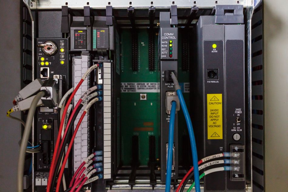
The common applications include:
Water and Wastewater Treatment: PLCs control pumps, valves, and chemical dosing equipment using measurements such as tank level, flow rate, and pressure. For example, a controller can start a pump when reservoir levels fall and stop it when it reaches the target level. SCADA brings information from treatment stages and remote pumping stations into a central interface, helping operators monitor conditions, investigate alarms, and review trends. CISA also identifies data collection and alarm notification among PLC responsibilities, demonstrating that these functions can extend into the field layer. [7]
Oil and Gas Pipelines: Operators must supervise equipment distributed across long distances. Local controllers and remote terminal units (RTUs) provide field control and telemetry, while SCADA consolidates measurements and equipment status at a control centre. Operators can use this information to assess operating conditions and issue supervisory commands. The oil and natural gas pipelines are commonly associated with SCADA applications.
Electrical Transmission and Distribution: SCADA gives control-room personnel visibility across substations and other distributed electrical assets. Field equipment can include RTUs, intelligent electronic devices, protective relays, and PLCs, depending on the installation. This makes electrical networks an important qualification for the PLC–SCADA model: a supervisory system may communicate with several types of field devices. The electrical utility transmission and distribution is a principal SCADA domain.
Manufacturing and Production Lines: PLCs execute machine sequences, coordinate conveyors, process sensor signals, and control actuators. Where several machines or production areas require shared supervision, SCADA can aggregate operating states, production counts, alarms, and process measurements. For example, operators can compare equipment trends with stoppage records to investigate recurring interruptions. A standalone machine may need only a PLC and local HMI; wider supervisory requirements determine whether SCADA adds value.
Rail and Transportation Infrastructure: SCADA supports centralized supervision of geographically distributed transport assets. [1] Its role must be distinguished from dedicated signalling, protection, and other safety functions. The supervisory interface provides operational visibility, while the appropriate local control and safety systems retain responsibility for time-critical actions.
Remote Sites and Telemetry: Pumping stations, reservoirs, and other isolated assets may communicate through radio, cellular, satellite, or wired networks. RTUs or communications-enabled controllers relay measurements and equipment status to SCADA. Link reliability, available bandwidth, and communication delays influence how frequently information reaches operators. Local control behaviour during a connection loss must therefore be defined explicitly.
IIoT and Predictive Maintenance: Historian records can support analysis of equipment condition, operating trends, and recurring faults. [6] Predictive maintenance may also require additional sensors or faster data acquisition than routine SCADA logging provides. These analytical capabilities complement the control architecture by informing maintenance decisions while PLCs continue executing local control.
The division of responsibilities remains application-dependent. Controllers may generate alarms and buffer data, while SCADA interfaces and historians provide centralized presentation and long-term records. [6] Defining these responsibilities clearly helps prevent gaps in monitoring, duplicated functions, and unnecessary dependence on supervisory communications.
Conclusion
PLC and SCADA are not competitors. PLC is a deterministic controller bounded by its scan cycle, capable of running a process alone. SCADA is a supervisory system that becomes necessary when assets are dispersed, and centralized data acquisition matters as much as control.
The design question is not which to use. It is where the boundary sits, which protocol crosses it, and whether that crossing is authenticated. On the last point, the honest answer for much of the installed plant is still no.
Frequently Asked Questions
Q. Is SCADA the same as a PLC?
A. No. PLC is a solid-state control system with user-programmable memory that implements functions such as I/O control, logic, timing and PID control. SCADA integrates data acquisition, data transmission, and HMI software to provide centralized monitoring and control. PLCs serve as control components within SCADA architectures.
Q. Can a PLC work without SCADA?
A. Yes. PLCs can be implemented as the primary controller in smaller configurations, controlling discrete processes such as automobile assembly lines. Those topologies generally lack a central control server or HMI and provide closed-loop control with minimal human involvement.
Q. Can SCADA work without a PLC?
A. Not usefully in most designs. SCADA field sites consist of RTUs and/or PLCs that control actuators and monitor sensors, and the RTU or PLC controls the local process while the control server stores and processes the information. Something has to close the control loop in the field.
Q. What is the difference between a PLC and an RTU?
A. An RTU is a computer with radio interfacing used where wired communication is unavailable, typically to communicate with remote field equipment. PLCs with radio communication capabilities are also used in place of RTUs. Functionally, they have converged.
Q. What languages are used to program a PLC?
A. IEC 61131-3:2025 specifies Structured Text as the textual language and Ladder Diagram and Function Block Diagram as graphical languages, plus Sequential Function Chart elements for structuring programs. The withdrawn 2013 edition also listed Instruction List.
Q. How fast is a PLC scan cycle?
A. It depends on the CPU and the program, and it varies between cycles because processing times differ. For scale, a Siemens S7-1500 has a default minimum cycle time of one millisecond and a default maximum cycle monitoring time of 150 milliseconds.
Q. What is the difference between SCADA and DCS?
A. SCADA emphasizes wide-area supervisory data acquisition, while DCS emphasizes localized continuous control with heavy inter-controller communication, though the boundary has blurred as both have adopted Ethernet networking and shared HMI conventions. DCS controls production systems within the same geographic location.
References
[1] NIST. Guide to Operational Technology (OT) Security [Cited 2026 September 20] Available at: Link
[2] IEC. 61131-3:2025 - Programmable Controllers, Part 3: Programming Languages [Cited 2026 September 20] Available at: Link
[3] IEC. 61131-3:2013, Programmable Controllers, Part 3: Programming Languages [Cited 2026 September 20] Available at: Link
[4] Modbus Organization. MODBUS Application Protocol Specification [Cited 2026 September 20] Available at: Link
[5] Siemens. SIMATIC S7-1500 Cycle and Response Times [Cited 2026 September 20] Available at: Link
[6] Arxiv. Cyber Security of OT Networks: A Tutorial, Survey of Attacks and Overview of Current State of Defense Tools, Protocols, & Challenges [Cited 2026 September 20] Available at: Link
[7] CISA. Exploitation of Unitronics PLCs used in Water and Wastewater Systems [Cited 2026 September 20] Available at: Link
[8] IEEE Std 1815-2012. IEEE Standard for Electric Power Systems Communications, Distributed Network Protocol (DNP3) [Cited 2026 September 20] Available at: Link
[9] IEEE P1815. IEEE Draft Standard for Electric Power Systems Communications, Distributed Network Protocol (DNP3) [Cited 2026 September 20] Available at: Link
[10] PI North America. PROFIBUS Technology Overview [Cited 2026 September 20] Available at: Link
in this article
1. Key Takeaways2. Introduction3. What a PLC Actually Does?4. What a SCADA System Actually Does?5. PLC vs SCADA: The Core Differences6. How PLC and SCADA Work Together?7. Security: The Shared Attack Surface8. Design Considerations and Common Mistakes9. Applications10. Conclusion11. Frequently Asked Questions12. References