PLC Programming: A Comprehensive Guide to Mastering the Art of Automation
Programmable Logic Controllers (PLCs) are the backbone of industrial automation, and PLC programming is the tool that brings these systems to life. In this article, we’ll take a look into the PLC basics, its programming process, programming language (with best practices), and tools to achieve this.

16 Jan, 2024. 21 minutes read
Introduction to PLC Programming
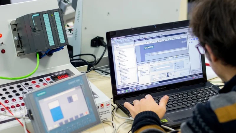
Programmable Logic Controllers (PLCs) are specialized computers widely used in industrial and manufacturing processes for automation and control. Renowned for their reliability and robustness, PLCs seamlessly manage machinery operations, assembly lines, and process controls.
PLC programming is a method of creating instructions for PLCs to follow, enabling them to control machinery and processes in industries such as manufacturing, energy, and transportation. The importance of PLC programming in automation cannot be overstated, especially when coupled with HMI & SCADA.
Programming a PLC allows for precise control of complex systems, improving efficiency, safety, and productivity. With PLC programming, tasks that would otherwise require manual intervention can be automated, reducing the potential for human error and freeing up the workforce for other tasks.
Furthermore, PLC programming allows for flexibility and adaptability in industrial processes, as the program can be easily modified to accommodate changes in the system or process it controls. Let’s delve further into the basics of PLC and its programming.
Basics of PLC
A Programmable Logic Controller (PLC) is a specialized computer used for industrial automation. Unlike general-purpose computers, PLCs withstand harsh industrial environments, such as those with high levels of noise, dust, and temperature extremes.
What is a PLC?
A PLC is a digital electronic device that uses a programmable memory to store instructions and to implement functions such as logic, sequencing, timing, counting, and arithmetic in order to control machines and processes. It is designed to be flexible and robust, capable of withstanding harsh industrial environments and handling real-time applications.
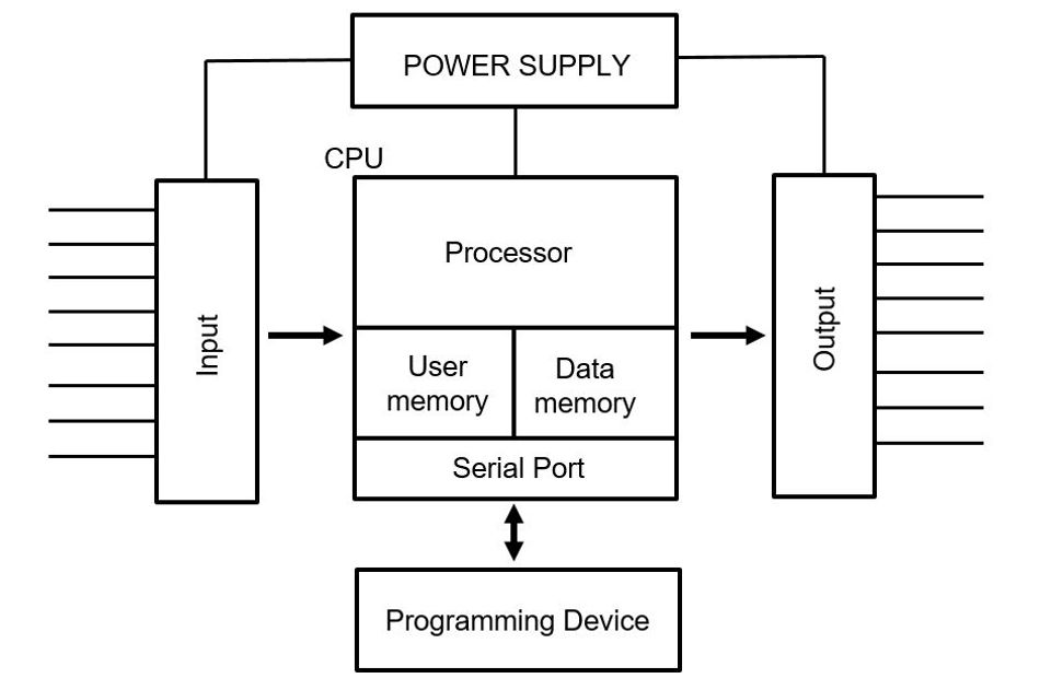
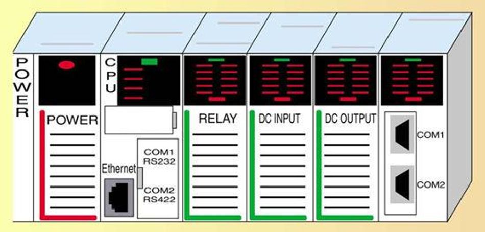
The main components of a PLC include:
- Power supply: It provides the necessary power for the PLC and its I/O modules.
- Processor: It executes the control program stored in its memory, and
- I/O modules: It provides the interface between the PLC and the devices it controls.
- Programming Device: It is responsible for configuring and controlling the PLC's operation.
The power supply, processor, I/O modules, and programming device are housed in a rack or chassis, which serves as the physical structure for the PLC.
Power Supply
The power supply powers the PLC and its I/O modules. It converts the incoming AC power to the DC power required by the PLC. The power supply must be able to provide sufficient power for the PLC and all of its I/O modules.
Processor
The processor, also known as the CPU, is the brain of the PLC. It executes the control program, processes data, and manages communication with other devices. The processor's speed, memory capacity, and communication capabilities can vary widely depending on the specific PLC model.
I/O modules
The I/O modules provide the interface between the PLC and the devices it controls. Input modules receive signals from input devices such as sensors and switches, while output modules send signals to output devices such as motors and lights. The number and type of I/O modules can be customized to meet the specific needs of the control system. The I/O can be an analog input or digital depending on the requirements.
Programming Device
The programming device serves as the interface between the human operator or programmer and the PLC itself, allowing users to input instructions, logic, and data into the programmable controller.
Allen Bradley, Siemens, and Rockwell Automation are well-known standout leaders in the PLC manufacturing industry.
How Does a PLC Work?
A PLC operates by continually scanning and executing a program. The process runs in the following order:
- The PLC reads the status of the inputs, which are connected to various field devices such as sensors and switches.
- The PLC then executes the control program that is stored in its memory, using the status of the inputs and the logic of the program to determine the state of the outputs.
- Finally, the PLC updates the status of the outputs, which are connected to devices such as motors and lights.
Modern PLCs can complete a scan cycle [1] in a matter of milliseconds, allowing them to control even high-speed processes.
The control program that the PLC executes is written in one of several PLC programming languages (as discussed later). This program contains the logic that the PLC uses to make decisions. For example, a simple control program might contain logic that turns on a motor when a switch is activated and turns off the motor when the switch is deactivated.
The flexibility of PLC programming allows implementation of complex control systems. For example, a PLC program could control a manufacturing process that involves multiple machines, with each machine performing a different task. The PLC could coordinate the operation of these machines, ensuring that each machine performs its task at the right time and in the right order.
In addition to controlling outputs based on inputs and program logic, a PLC can also perform other functions such as timing, counting, and arithmetic operations. These functions can be used to implement more complex control strategies. For example, a PLC could use a timer to control a process that needs to occur for a specific amount of time, or it could use a counter to control a process that needs to occur a specific number of times.
Having an understanding about the basics of PLC, let’s explore ots programming process.
Suggested Reading: What is a PLC (Programmable Logic Controllers): A Comprehensive Guide
PLC Programming Process
The PLC programming process involves several steps, from understanding the control task, to testing and deploying the control program. This process is iterative, with each step building on the previous ones and often requiring revisions based on the results of testing and evaluation.
Understanding the Control Task
Understanding the control task is the first and arguably the most critical step in the PLC programming process. It involves a thorough analysis of the requirements of the control system, including the desired behavior of the plc system, the inputs and outputs of the PLC, and any constraints or limitations of the system.
The desired behavior of the system is typically defined in terms of the system's response to various inputs and conditions. This may include the sequence of operations to be performed, the conditions under which these operations should be carried out, and the expected outcomes of these operations.
The inputs and outputs of the PLC are the points of interaction between the PLC and the controlled system. Inputs may include sensors, switches, and other devices that provide information about the state of the system, while outputs may include actuators, indicators, and other devices that the PLC can control to affect the state of the system.
Constraints and limitations of the system may include physical constraints, such as the maximum speed of a motor or the range of a sensor, as well as operational constraints, such as safety requirements or production targets. These constraints and limitations must be taken into account when designing the control program to ensure that the program is feasible and safe to implement.
Understanding the control task requires a deep understanding of the controlled system and its operation, as well as the ability to translate this understanding into a clear and precise specification for the control program. This specification serves as the blueprint for the design and implementation of the control program, guiding the choice of programming language, the design of the control strategy, and the implementation of the control logic.
Suggested Reading: PID Loops: A Comprehensive Guide to Understanding and Implementation
Developing the PLC Program
Developing the PLC program is the next step in the PLC programming process, following the understanding of the control task. This step involves designing and implementing the control strategy using the chosen programming language and adhering to the requirements and constraints identified during the analysis of the control task.
The development process typically involves the following stages:
- Designing the Control Strategy: The control strategy is the overall approach to achieving the desired behavior of the controlled system. It defines the sequence of operations, the conditions under which these operations should be carried out, and the expected outcomes of these operations. The control strategy should take into account the inputs and outputs of the PLC, as well as any constraints or limitations of the system.
- Implementing the Control Logic: The control logic is the set of instructions that the PLC will execute to implement the control strategy. This involves translating the control strategy into a series of programming statements or graphical elements, depending on the chosen programming language. The control logic should be designed to be efficient, reliable, and easy to understand and maintain.
- Organizing the Program: A well-organized program is easier to understand, maintain, and troubleshoot. This involves structuring the program into logical sections or modules, using functions or function blocks to encapsulate complex logic, and using comments and descriptive variable names to improve readability.
- Optimizing the Program: Optimizing the program involves identifying and addressing any inefficiencies or bottlenecks in the control logic. This may include reducing the complexity of the logic, minimizing the use of resources such as memory and processing power, and improving the responsiveness of the program to changes in the controlled system.
- Documenting the Program: Proper documentation is essential for ensuring the long-term maintainability and reliability of the PLC program. This includes creating a clear and concise description of the control strategy, the control logic, and any assumptions or constraints that were considered during the development process. Documentation should also include any relevant information about the PLC hardware, the connected devices, and the communication protocols used.
Throughout the development process, it is important to keep in mind the requirements and constraints identified during the analysis of the control task. The PLC program should be designed to meet these requirements while adhering to any constraints or limitations of the system. Regular testing and evaluation of the program can help to identify any issues or deviations from the desired behavior, allowing for adjustments and refinements to be made as needed.
Testing and Debugging the PLC Program
Testing and debugging are crucial steps in the PLC programming process, as they ensure reliability and correctness of the control program. These steps involve identifying and correcting any errors or issues in the program, as well as verifying that the program meets the requirements of the control task and adheres to any constraints or limitations of the system.
The testing and debugging process typically involves the following stages:
- Unit Testing: Unit testing focuses on testing individual components or sections of the program in isolation. This identifies any issues or errors in the control logic, as well as any discrepancies between the program and the control task requirements. Unit testing can be performed using a PLC simulator or by connecting the PLC to a test setup that mimics the controlled system.
- Integration Testing: Integration testing involves testing the program as a whole, with all components and sections working together. This identifies any issues or errors that may arise from the interactions between different parts of the program, as well as any discrepancies between the program and the overall control strategy. Integration testing can be performed using a PLC simulator or by connecting the PLC to the actual controlled system.
- Debugging: Debugging is the process of identifying and correcting errors or issues in the program. This involves analyzing the program's behavior, examining the values of variables and the state of the PLC's inputs and outputs, and stepping through the program's execution to identify the cause of any issues. Debugging can be performed using the debugging tools provided by the PLC programming software, such as breakpoints, watch variables, and single-stepping.
- Validation: Validation is the process of verifying that the program meets the requirements of the control task and adheres to any constraints or limitations of the system. This involves comparing the program's behavior to the desired behavior of the controlled system, as well as ensuring that the program complies with any safety or performance requirements. Validation can be performed using a combination of testing, simulation, and analysis.
Throughout the testing and debugging process, it is important to maintain a systematic and methodical approach, documenting any issues or errors that are identified and the steps taken to correct them. This documentation can be invaluable in ensuring the long-term maintainability and reliability of the PLC program, as well as in identifying any patterns or trends in the types of issues that arise during the development process.
PLC Programming Languages
PLC programming languages [3] are the tools used to create control programs for PLCs. There are several languages defined by the IEC 61131-3 standard, which is the international standard for PLC programming languages. These languages include Ladder Diagram (LD), Structured Text (ST), Function Block Diagram (FBD), Instruction List (IL), and Sequential Function Chart (SFC). Each language has its own strengths and weaknesses, and the choice of language depends on the specific requirements of the control system and the preferences of the programmer.

Ladder Diagram (LD) or Ladder Logic Programming is a graphical programming language that is widely used in PLC programming. It is based on the concept of relay logic [2], which was used in early control systems before the advent of PLCs. LD uses symbols to represent various components, such as contacts, coils, and timers, which are arranged in a ladder-like structure.
In LD, each rung of the ladder represents a logical operation. The rungs are read from left to right, with the input conditions on the left and the output actions on the right. When the input conditions are met, the output actions are executed. The symbols used in LD are designed to be intuitive and easy to understand, making it a popular choice for programmers who are new to PLC programming.
Some key elements of Ladder Diagram programming include:
- Contacts: Contacts represent input devices, such as switches and sensors. They can be normally open (NO) or normally closed (NC), depending on their default state when no input is applied.
- Coils: Coils represent output devices, such as motors and lights. When a coil is energized, the corresponding output device is activated.
- Timers and Counters: Timers and counters are used to implement time-based and count-based control strategies. They can be used to delay the activation of an output or to control the number of times an output is activated.
- Comparison and Arithmetic Operations: LD supports various comparison and arithmetic operations, such as greater than, less than, equal to, addition, subtraction, multiplication, and division. These operations can be used to implement more complex control strategies.
When programming in a Ladder Diagram, it is essential to understand the flow of logic and the execution order of the rungs. This understanding creates efficient and reliable control programs that meet the requirements of the control system.
Further Reading: Exploring Ladder Logic Programming: An In-depth Exploration
Structured Text (ST)
Structured Text (ST) is a high-level, text-based programming language which is used to program a PLC. It is similar to other high-level programming languages, such as C and Pascal, making it a familiar choice for programmers with experience in those languages. ST is particularly well-suited for complex control tasks and mathematical operations, as it allows for more advanced programming constructs and greater flexibility in implementing control strategies.
In ST, programs are written using statements and expressions, which are executed sequentially. The language supports various control structures, such as loops, conditional statements, and function calls, allowing for the creation of complex control algorithms. Variables and data types are also an essential part of ST programming, as they enable the storage and manipulation of data within the program.
Some key elements of Structured Text programming include:
- Variables and Data Types: ST supports a wide range of data types, including boolean, integer, real, and string. Variables are used to store and manipulate data, and their data type determines the kind of data they can hold and the operations that can be performed on them.
- Control Structures: Control structures, such as IF-THEN-ELSE, FOR, and WHILE, are used to control the flow of the program. They allow for conditional execution of code and the creation of loops, enabling more complex control strategies.
- Functions and Function Blocks: Functions and function blocks are reusable pieces of code that can be called from within the program. Functions return a single value, while function blocks can have multiple outputs and can maintain internal state between calls. Both functions and function blocks can be used to encapsulate complex logic and improve the modularity and maintainability of the program.
- Arithmetic and Logical Operations: ST supports a wide range of arithmetic and logical operations, such as addition, subtraction, multiplication, division, AND, OR, and NOT. These operations can be used to implement complex control strategies and mathematical calculations.
When programming in Structured Text, it is essential to understand the syntax and structure of the language, as well as the available control structures and data types. This understanding creates efficient and reliable control programs that meet the requirements of the control system.
Function Block Diagram (FBD) is a graphical programming language used in PLC programming. It is based on the concept of connecting function blocks, which represent predefined functions or operations, to create a control program. FBD is particularly well-suited for implementing control strategies that involve complex interconnections between different functions, as it provides a clear and intuitive representation of the relationships between these functions.
In FBD, function blocks are represented by graphical symbols, and their inputs and outputs are connected using lines, called connections. The flow of data and control signals between function blocks is represented by the connections, which are drawn from left to right. Function blocks can be connected in series, parallel, or in more complex configurations, depending on the requirements of the control strategy.
Some key elements of Function Block Diagram programming include:
- Function Blocks: Function blocks are the building blocks of FBD programs. They represent predefined functions or operations, such as addition, multiplication, timers, and counters. Function blocks can have multiple inputs and outputs, and their behavior is determined by their internal logic and the values of their inputs.
- Connections: Connections are used to link the inputs and outputs of function blocks, creating a flow of data and control signals between them. Connections are drawn from left to right, indicating the direction of data flow.
- Data Types and Variables: FBD supports various data types, such as boolean, integer, real, and string. Variables are used to store and manipulate data, and their data type determines the kind of data they can hold and the operations that can be performed on them. Variables can be connected to the inputs and outputs of function blocks, allowing data to flow between them.
- Conditional Execution and Looping: FBD supports conditional execution and looping through the use of specific function blocks, such as the IF and FOR blocks. These blocks can be used to create more complex control strategies that involve decision-making and repetition.
When programming in a Function Block Diagram, it is essential to understand the available function blocks, their inputs and outputs, and how they can be connected to create a control program. This understanding helps to create efficient and reliable control programs that meet the requirements of the control system.
PLC Programming Tools
PLC programming tools are software applications that provide an environment for creating, testing, and deploying control programs for PLCs. These tools typically include features such as a code editor, a compiler, a debugger, and a simulator. They also provide support for various PLC programming languages, allowing programmers to choose the language that best suits their needs.
PLC programming tools are provided by the PLC manufacturer, ensuring compatibility between the tool and the PLC. However, there are also third-party tools available that support a wide range of PLCs from different manufacturers. These tools often provide additional features, such as advanced debugging capabilities, version control, and collaborative programming.
PLC Simulators
PLC simulators (check link for a ladder logic simulator screenshot) are PLC programming tools that allow control programs to be tested without the need for a physical PLC. They simulate the behavior of a PLC, including its inputs, outputs, and internal operations. This allows programmers to verify the functionality of their control program and identify any errors or issues before the program is deployed to a real PLC.
PLC simulators are beneficial in numerous ways:
- They provide a virtual representation of the PLC and its connected devices.
- Inputs can be manually controlled by the user, allowing different scenarios to be tested.
- The state of the outputs and the internal variables of the PLC can be monitored, providing insight into the operation of the control program.
- Using a PLC simulator can save time and reduce costs [4], as it allows issues to be identified and resolved before the control program is deployed.
- It also reduces the risk of damage to the PLC or its connected devices, as any errors in the control program can be identified and corrected in the simulator before the program is run on a real PLC.
- They are also a valuable learning tool, as they allow new programmers to gain experience with PLC programming without the need for a physical PLC.
PLC simulators are particularly useful in the development of complex control systems, where testing the control program on a real PLC would be difficult or impractical.
PLC Programming Software
PLC programming software is a PLC programming tool that provides an environment for creating, editing, compiling, and deploying control programs for PLCs. This PLC software includes a code editor for writing and editing code, a compiler for translating the code into a format that can be executed by the PLC, and a debugger for identifying and correcting errors in the code.
PLC programming software supports various PLC programming languages, such as Ladder Diagram (LD), Structured Text (ST), Function Block Diagram (FBD), Instruction List (IL), and Sequential Function Chart (SFC). This allows programmers to choose the language that best suits their needs and the requirements of the control system.
In addition to these basic features, PLC programming software often includes advanced features that enhance productivity and ease of use. These may include code completion, syntax highlighting, and automatic error detection, which help to reduce coding errors and improve the readability of the code. Some software also includes project management features, such as version control and collaborative programming, which facilitate teamwork and ensure the integrity of the code.
PLC programming software also includes a PLC simulator, which allows the control program to be tested without the need for a physical PLC. The simulator mimics the behavior of a PLC, including its inputs, outputs, and internal operations. This allows programmers to verify the functionality of their control program and identify any errors or issues before the program is deployed to a real PLC.
PLC programming software is typically provided by the manufacturer of the PLC, ensuring compatibility between the software and the PLC. However, there are also third-party software available that support a wide range of PLCs from different manufacturers. These software often provide additional features and capabilities, such as support for multiple programming languages and advanced debugging tools. OpenPLC Editor, Studio 5000, TwidoSuite, Ladder Editor are a few of the popular PLC programming softwares. RSLogix 500 is another notable software tool associated with Rockwell Automation's PLCs. With the help of various PLC language tutorials available online, it is easier to learn PLC programming.
Advanced PLC Programming Concepts
Advanced PLC programming concepts extend beyond the basic control logic and involve more complex functionalities that can enhance the performance and capabilities of a PLC. These advanced concepts include timers and counters, data handling and manipulation, and communication and networking, among others. Understanding these concepts can enable a PLC programmer to develop more sophisticated and efficient control programs that meet a wider range of control requirements and handle more complex control tasks.
PLC Timers and Counters
Timers and counters are fundamental components of PLC programming that provide the ability to control the timing and counting operations within a control program. They are used in a wide range of applications, from simple timing and counting tasks to complex sequencing and synchronization operations.
PLC Timers are used to delay the execution of certain parts of the program or to perform actions at specific intervals. They work by counting the amount of time that has passed since they were activated, and triggering an action when a specified time duration has been reached. There are typically three types of timers in a PLC: On-Delay Timer (TON), Off-Delay Timer (TOF), and Retentive On-Delay Timer (RTO). Each type of timer has a unique behavior that makes it suitable for different types of timing operations [5].
PLC Counters are used to count the number of occurrences of a certain event, such as the activation of a sensor or the completion of a cycle. They work by incrementing or decrementing a count value each time a specified event occurs, and triggering an action when a specified count value has been reached. There are typically two types of counters in a PLC: Count Up Counter (CTU) and Count Down Counter (CTD). Each type of counter has a unique behavior that makes it suitable for different types of counting operations.
Both timers and counters are implemented as special function blocks in the PLC programming software [6], with inputs for controlling their operation (such as start, reset, and preset value inputs), and outputs for indicating their status (such as done, timing, and overflow outputs). The behavior of these function blocks is defined by the PLC's instruction set and can vary between different PLC models and manufacturers.
PLC Data Types and Addressing
In PLC programming, data types and addressing are key concepts that govern how data is stored, accessed, and manipulated within the PLC. Understanding these concepts is crucial for designing efficient and effective control programs.
PLC Data Types refer to the different kinds of data that a PLC can handle. These typically include Boolean data (true/false or on/off), numerical data (integer or real numbers), and more complex data types such as timers, counters, and data structures. Each data type has a specific size and format, which determines how much memory it occupies in the PLC and how it can be manipulated by the program. For example, a Boolean data type typically occupies one bit of memory and can be manipulated using logical operations, while a real number data type typically occupies 32 bits of memory and can be manipulated using arithmetic operations.
PLC Addressing refers to the system used to identify and access the different memory locations within the PLC where data is stored. Each memory location in the PLC has a unique address, which can be used to read the data stored at that location or to write new data to that location. The addressing system used by a PLC typically includes different address spaces for different types of data (such as inputs, outputs, and internal memory), and may also include different address spaces for different data types (such as bits, words, and blocks). The specific format and structure of the addresses can vary between different PLC models and manufacturers.
Understanding the data types and addressing system used by a PLC is crucial for designing efficient and effective control programs. It allows the programmer to make optimal use of the PLC's memory resources, to implement complex data manipulation operations, and to interface effectively with the PLC's inputs and outputs and with other devices in the control system. It also forms the basis for more advanced programming concepts such as data handling and manipulation, and communication and networking.
PLC Programming Best Practices
PLC programming best practices are guidelines and recommendations that can help to ensure the quality, reliability, and maintainability of PLC programs. These best practices cover various aspects of the PLC programming process, from the initial design and development of the program to its testing, debugging, and documentation.
- Modular Programming: Modular programming involves structuring the program into separate modules or sections, each of which performs a specific task or function. This can make the program easier to understand, maintain, and troubleshoot, as well as allowing for code reuse and better organization of the program. Each module should be designed to be as independent as possible, with clear inputs and outputs and minimal dependencies on other modules.
- Descriptive Names: Using descriptive names for variables, functions, and other elements of the program improves the readability and understandability of the program. The names should clearly indicate the purpose or function of the element, and should be consistent and meaningful.
- Commenting and Documentation: Commenting involves adding explanatory notes to the program code, to explain the purpose and operation of different parts of the program. Documentation involves creating a separate document that provides a detailed description of the program, including its design, operation, and any assumptions or constraints that were considered during its development. Both commenting and documentation are crucial for ensuring the long-term maintainability and reliability of the program.
- Error Handling: Error handling involves designing the program to detect and respond to errors or abnormal conditions that may occur during its operation. This can include things like sensor failures, communication errors, or unexpected inputs. The program should be designed to handle such errors in a safe and predictable manner, to prevent damage to the system or unsafe conditions.
- Testing and Debugging: Regular testing and debugging of the program can help to identify and correct any errors or issues, and to ensure that the program is functioning correctly and meeting its requirements. This should include both unit testing of individual components or sections of the program, and integration testing of the program as a whole.
PLC programming is a constantly evolving field, with new techniques, tools, and best practices being developed all the time. It is important for PLC programmers to stay up-to-date with these developments, and to continuously learn and improve their programming skills. This can involve attending training courses, reading industry publications, participating in online forums or communities, and experimenting with new techniques or tools.
Conclusion
PLC programming is a critical skill in the field of industrial automation and control. The effectiveness of a PLC program can significantly impact the efficiency, safety, and reliability of the controlled system, making it a key factor in the success of any industrial operation.
The process of PLC programming involves several stages, from the initial design and development of the program to its testing, debugging, and maintenance. Each stage requires a thorough understanding of the control task, the capabilities and limitations of the PLC, and the principles of control logic and programming.
Advanced PLC programming concepts, such as timers and counters, data handling and manipulation, and communication and networking, can enhance the performance and capabilities of a PLC program. These concepts allow a PLC programmer to develop more sophisticated and efficient control programs that can meet a wider range of control requirements and handle more complex control tasks.
PLC programming best practices, such as modular programming, use of descriptive names, commenting and documentation, error handling, and continuous learning and improvement, can help to ensure the quality, reliability, and maintainability of PLC programs. These best practices provide a framework for developing effective and efficient PLC programs, and for continuously improving and updating these programs to meet changing requirements and take advantage of new developments in the field.
FAQs
1. What is a PLC?
A Programmable Logic Controller (PLC) is a specialized computer used to control machines and processes in an industrial setting. It is designed to be robust and reliable, capable of operating in harsh industrial environments, and to provide real-time control of the controlled system.
2. What is PLC programming?
PLC programming is the process of creating a control program for a PLC. This program defines the logic that the PLC uses to control the operations of the machines or processes in the controlled system.
3. What are some advanced PLC programming concepts?
Advanced PLC programming concepts include timers and counters, data handling and manipulation, and communication and networking. These concepts allow a PLC programmer to develop more sophisticated and efficient control programs that can meet a wider range of control requirements and handle more complex control tasks.
4. What are some PLC programming best practices?
PLC programming best practices include modular programming, use of descriptive names, commenting and documentation, error handling, and continuous learning and improvement. These best practices can help to ensure the quality, reliability, and maintainability of PLC programs.
References
[1] Instrumentation Tools. PLC Scan Time. Link
[2] Ladder Logic World. Relay Logic Vs Ladder Logic. Link
[3] Controleng. PLC Programming Languages. Link
[4] Research Gate. Control System Simulator with PLC. Link
[5] Realpars. PLC Timer Programming for Beginners. Link
[6] Electronic Clinic. PLC Timers and Counters, their types and Practical Uses. Link