Modbus RTU: A Comprehensive Guide to Understanding and Implementing the Protocol
Owing to its simple and straightforward nature, Modbus RTU is the engineer and technician's go-to protocol in industries such as manufacturing, energy, and transportation. Understanding Modbus RTU is crucial for seamless communication between electronic devices and optimizing system performance.

Last updated on 30 Jan, 2025. 16 minutes read

Introduction to Modbus RTU
Modbus RTU is a cornerstone protocol in industrial automation, widely recognized for its simplicity and efficiency in facilitating reliable communication between devices over serial connections. Some of these devices include PLCs, HMIs, and SCADA systems.
It has become a de facto standard for connecting sensors, actuators, and controllers in various automation systems. Its key advantages are low implementation costs, robust error-checking mechanisms, and seamless integration into existing infrastructures.
In this comprehensive guide, we will delve into the essential aspects of Modbus RTU, including its architecture, technical specifications, and practical implementation strategies. By addressing these complexities, the content will help you deploy and manage Modbus RTU systems effectively in modern industrial environments.

Modbus RTU Protocol Overview
Operating on a master-slave architecture, Modbus RTU enables communication between Programmable Logic Controllers (PLCs) and various electronic devices such as sensors, actuators, and controllers, connected to a shared communication channel.
Each Modbus message follows a structured format consisting of an address field, function code, data field, and checksum. The master initiates a request, specifying the starting address and required Modbus registers, while the slave responds with the requested data. The protocol supports both RTU communication (binary encoding for efficiency) and ASCII mode (human-readable but slower).
Data transmission occurs via serial interfaces such as RS-232, RS-485, or RS-422, ensuring compatibility across industrial networks. The checksum (Cyclic Redundancy Check, CRC) validates data integrity, making Modbus RTU a reliable and robust solution for data acquisition and control in SCADA and automation applications.
Modbus RTU remains a top choice in industrial automation due to its simplicity, reliability, and widespread adoption. Its efficient binary encoding ensures fast communication, while the master-slave model allows seamless integration with PLCs, SCADA, and RTUs. Additionally, its support for various transport layers and low implementation cost make it ideal for industrial control systems.
Transport Layers (RS-232 & RS-485)
Modbus RTU operates over RS-232 and RS-485 serial interfaces. RS-232 supports point-to-point communication over short distances, ideal for basic setups. RS-485, on the other hand, allows multi-drop networking, supporting multiple devices over long distances with better noise immunity. Both layers ensure reliable Modbus communication, depending on system requirements.
Modbus RTU Frame Structure
The RTU frame structure forms the backbone of the Modbus RTU communication protocol, defining the organization and transmission of Modbus data between devices. This transmission is enabled through the transport layer which encompasses protocols and techniques utilized to ensure reliable and efficient data transfer. A Modbus RTU frame consists of several components that enable efficient and accurate data transmission. The frame structure includes the following elements:
+------------------+------------------+------------------+------------------+
| Address (1 byte) | Function (1 byte)| Data (N bytes)   | CRC (2 bytes)    |
+------------------+------------------+------------------+------------------+
The Modbus RTU frame consists of four main components:
- Address Field (1 byte): Identifies the target slave device. The value ranges from 1 to 247, with 0 reserved for broadcast.
- Function Code (1 byte): Indicates the type of action the master requests, such as reading or writing data.
- Data Field (N bytes): Contains the information relevant to the function, including register addresses and values.
- CRC Field (2 bytes): Provides error checking using a cyclic redundancy check.
- Slave Address (1-byte): This field is a unique identifier assigned to each slave device in the network, allowing the master device to communicate with specific slave devices. Since it’s an 8-bit value, it accepts the range 0-247.
- Function Code (1-byte): It is a numerical code that specifies the type of action or request being made by the master device, such as reading or writing data.
- Data: The data field is the actual modbus message being transmitted, which can be the values being written/read from the slave registers. The size can vary in length depending on the function code and the specific operation to be performed.
- Error Check (2-byte): Modbus RTU uses a cyclic redundancy check (CRC) for checking errors. It is used to verify the integrity of the transmitted data and detect potential communication errors.
- Silent Period: The silent period is the idle time between consecutive frames, during which the communication line remains quiet. It serves as a minimum gap period that separates two frames, indicating the start and end of the message. The silent period plays a crucial role in frame synchronization and helps ensure the reliable transmission of Modbus RTU frames over the communication line.
The combination of these components allows for efficient and reliable data exchange between devices in a Modbus RTU network.
Timing Diagram for Character Intervals
|<-- T1.5 -->|<- Data Byte ->|<-- T1.5 -->|
- T1.5: Represents a silent interval between characters. Typically, it is 1.5 times the character transmission time.
- Data Byte: Represents each byte of the Modbus RTU frame, transmitted without gaps.
Modbus RTU Function Codes
Function codes play a crucial role in Modbus RTU communication, as they define the type of action or request made by the master device. Each function code corresponds to a specific operation, such as reading or writing data, and helps ensure accurate and efficient communication between devices. Below are the function codes of Modbus RTU:
| Function Code | Description |
| 01 | Read Coils |
| 02 | Read Discrete Inputs |
| 03 | Read Holding Registers |
| 04 | Read Input Registers |
| 05 | Write Single Coil |
| 06 | Write Single Holding Register |
| 15 | Write Multiple Coils |
| 16 | Write Multiple Holding Registers |
| Logical Address | Register Address | Description |
| 40001 | 0 | Holding Register 1 |
| 40002 | 1 | Holding Register 2 |
| 00001 | 0 | Coil 1 |
| 10001 | 0 | Discrete Input 1 |
Read Function Codes
Read function codes allow the master device to request data from slave devices. Some common read function codes include:
- Read Coils (0x01): This function code is used to read the status of multiple coils (digital outputs) in a slave device.
- Read Discrete Inputs (0x02): This function code is used to read the status of multiple discrete inputs (digital inputs) in a slave device.
- Read Holding Registers (0x03): This function code is used to read the values of multiple holding registers (analog outputs) in a slave device.
- Read Input Registers (0x04): This function code is used to read the values of multiple input registers (analog inputs) in a slave device.
Write Function Codes
Write function codes that enable the master device to send data to slave devices, modifying their internal states or settings. Some common write function codes include:
- Write Single Coil (0x05): This function code is used to write the status of a single coil (digital output) in a slave device.
- Write Single Register (0x06): This function code is used to write the value of a single holding register (analog output) in a slave device.
- Write Multiple Coils (0x0F): This function code is used to write the status of multiple coils (digital outputs) in a slave device.
- Write Multiple Registers (0x10): This function code is used to write the values of multiple holding registers (analog outputs) in a slave device.
By using function codes, Modbus RTU ensures that the master device can accurately request data from or send data to slave devices, facilitating efficient and reliable communication in industrial automation systems.
Modbus RTU Addressing
Addressing Modbus RTU is essential for ensuring that data is sent to and received from the correct devices. There are different types of addresses used in Modbus RTU:
- Slave Addresses: Each slave device in the network is assigned a unique address, ranging from 1 to 247. The master device uses these addresses to communicate with specific slave devices. The values 248 to 255 are reserved for other purposes.
- Data Addresses: Modbus RTU uses a hierarchical addressing scheme for data, which includes four primary types of data objects: coils, discrete inputs, input registers, and holding registers. Each data object has a specific address range, allowing the master device to access the desired data within a slave device.
In Modbus RTU, single-bit data is commonly exchanged between devices using coils or discrete inputs. Coils represent outputs, allowing control signals to be sent from the master to the slave, while discrete inputs represent inputs monitored by the slave and provide status information to the master. The single-bit nature of Modbus RTU enables efficient and precise control and monitoring of individual digital signals in industrial applications.
Let’s discuss how data addressing works in Modbus RTU, along with an example.
Modbus RTU communication involves the exchange of data through Modbus registers, which are predefined memory locations in the slave devices. Modbus registers can hold various types of data, such as holding registers for numerical values or coils for single-bit states. The master device can read or write to these Modbus registers, allowing for efficient and standardized access to critical data within the Modbus RTU network.
Linked is a table showing the address range of each register type referenced in the modbus devices.
Consider a scenario where you would like to read the data from the Holding Register of a slave device, addressed 17. The starting address of the 3 registers is from #40108 to 40110. This translates to the hexadecimal value of 6B (Subtracting 40108 from the offset value 40001, results in 107, which equals to 6Bh).
Since the function to be performed is reading from the Analog Output Holding Register, the function code will be 03.
The appropriate command for performing this operation will be 11 03 006B 0003 xxxx.
11: This is the hexadecimal equivalent of 17, the slave id.
03: Function code for reading the data from the holding register.
6B: Hexadecimal equivalent of the first registered address.
0003: Number of required registers.
xxxx: CRC checksum.
The above command will result in a response from the slave device with the stored register values that were addressed by the master device.
By using a well-defined addressing scheme, Modbus RTU ensures accurate and efficient data exchange between devices in an industrial automation system.
Modbus RTU Communication Modes
Modbus RTU supports two main communication modes: master/slave and client/server. Each mode has its advantages and disadvantages, depending on the specific requirements of the industrial automation system.
Master/Slave Mode
In the master/slave mode, one device, known as the master, initiates communication with other devices, called slaves. The master device sends requests to the slave devices, which then respond with the requested data or perform the specified action. This mode is characterized by the following features:
- Unidirectional communication: The master device initiates all communication, and slave devices only respond to requests from the master.
- Polling mechanism: The master device continuously polls each slave device for data or status updates, ensuring up-to-date information is available.
- Deterministic response times: Since the master device controls the communication, response times can be predictable and consistent.
The master/slave mode is suitable for applications where a central controller needs to manage multiple devices and deterministic response times are crucial.
Client/Server Mode
In the client/server mode, devices can act as both clients and servers, allowing for more flexible communication between devices. This mode is characterized by the following features:
- Bidirectional communication: Devices can initiate communication with each other, enabling more dynamic data exchange.
- Event-driven communication: Devices can send data or request information from other devices based on specific events or conditions, reducing unnecessary communication overhead.
- Scalability: The client/server mode can accommodate a larger number of devices and support more complex communication patterns.
The client/server mode is suitable for applications where devices need to communicate with each other directly and more complex communication patterns are required. However, it should be noted that Modbus RTU primarily operates in the master/slave mode, and the client/server mode is more commonly associated with Modbus TCP/IP, another variant of the Modbus protocol.
Modbus RTU Error Handling
Effective error handling is vital in Modbus RTU to promptly identify and resolve any communication errors between the master and slave devices. It also ensures reliable and accurate data exchange between the devices. Modbus RTU employs various mechanisms to detect and handle errors that may occur during communication.
Error Detection
Modbus RTU uses a cyclic redundancy check (CRC) to detect errors in the transmitted data. The CRC is a mathematical algorithm that calculates a checksum value based on the frame's content. The sender appends this checksum to the frame, and the receiver recalculates the CRC upon receiving the frame. If the calculated CRC matches the received CRC, the frame is considered error-free. Otherwise, an error is detected, and the receiver can request a retransmission. Modbus RTU uses a 16-bit CRC algorithm, specifically CRC-16.
Implementations of CRC calculation for Modbus RTU are available in various programming languages and libraries, simplifying the process for developers. By using the CRC mechanism, Modbus RTU ensures data integrity and facilitates error-free communication in industrial automation systems.
Error Codes
When a slave device encounters an error while processing a request from the master device, it responds with an exception message containing an error code. These error codes provide information about the nature of the error, allowing the master device to take appropriate action. Some common Modbus RTU error codes include:
- Illegal Function (0x01): The error code indicates that the requested function code is not supported by the slave device.
- Illegal Data Address (0x02): The error code indicates that the requested data address is not valid or out of the allowable range for the slave device.
- Illegal Data Value (0x03): The error code indicates that the data value provided in the request is not valid or allowed by the slave device.
- Slave Device Failure (0x04): The error code indicates that the slave device encountered an internal error while processing the request.
- Acknowledge (0x05): The error is sent by the slave device to indicate that it has received the request but needs additional time to process it.
- Slave device busy (0x06): Th error is sent by the slave device to indicate that it is busy executing some other command. The master should send the request once the slave device is available.
By using error codes, Modbus RTU enables efficient error handling and provides feedback to the user about potential issues in the communication process.
Timeout and Retransmission
In Modbus RTU communication, the master device expects a response from the slave device within a specified time frame, known as the timeout period. If the master device does not receive a response within this period, it assumes that an error has occurred, such as a lost frame or a non-responsive slave device. In such cases, the master device can attempt to retransmit the request or take other appropriate actions, such as reporting the error to the user or initiating a fault recovery process.
By employing error detection, error codes, and timeout mechanisms, Modbus RTU ensures reliable and accurate communication between devices in an industrial automation system.
Modbus RTU Troubleshooting
Troubleshooting is an essential aspect of maintaining and optimizing Modbus RTU communication in industrial automation systems. Identifying and resolving common issues can help ensure reliable and efficient data exchange between devices. Here are some typical problems and their solutions:
Communication failure between master and slave devices:
- Check the wiring and connections between devices, ensuring proper termination and shielding.
- Verify the configuration of master and slave devices, including baud rate, parity, and stop bits.
- Ensure that the slave device address in the master's request matches the actual address of the slave device.
Incorrect or inconsistent data values:
- Inspect the data addressing scheme, ensuring that the master device is requesting data from the correct registers or coils in the slave device.
- Verify the data types and scaling factors used in the communication, ensuring consistency between master and slave devices.
- Check for potential sources of electrical noise or interference that may corrupt the transmitted data.
Timeouts or slow response times:
- Adjust the timeout settings in the master device to account for communication delays or slow-responding slave devices.
- Inspect the network topology and communication distances, ensuring that they are within the limits specified by the Modbus RTU protocol and the chosen serial communication interface.
- Optimize the polling mechanism used by the master device, reducing the number of requests or prioritizing critical devices to minimize response times.
Error codes or exception messages:
- Analyze the error codes returned by the slave devices to identify the nature of the problem, such as illegal function codes, invalid data addresses, or device failures.
- Review the master device's requests to ensure they are valid and supported by the slave devices.
- Inspect the slave devices for potential hardware or software issues that may cause errors or failures.
- By following these troubleshooting tips, referring to the protocol specifications, and maintaining a proactive approach to identifying and resolving issues, you can ensure the reliability and efficiency of Modbus RTU communication in your industrial automation system.
Hardware Requirements
Technical Specifications for RS-485 Implementation
- Voltage Levels: Differential signaling with a minimum differential output of 1.5V.
- Bus Loading: Up to 32 nodes per segment with standard transceivers.
- Data Rates: Up to 10 Mbps over short distances; typical rates are 9600 bps to 115.2 kbps for industrial applications.
- Cable Impedance: 120 ohms characteristic impedance.
- Connectors: Typically uses DB-9 or RJ-45 connectors.
Termination and Biasing Requirements
- Use 120-ohm termination resistors at both ends of the RS-485 bus.
- Include pull-up and pull-down resistors (typically 10 kΩ) to bias the idle state.
- Ensure the biasing maintains a minimum differential voltage of 200 mV when the bus is idle.
ASCII Circuit Diagram for Typical Connections
Master (A/B) -------------------+------------------- Slave 1 (A/B)
                                |
                                +------------------- Slave 2 (A/B)
- A and B lines represent differential pair connections.
- Include termination resistors at the first and last devices in the network.
Cable Requirements and Limitations
- Cable Type: Shielded twisted pair (STP) or unshielded twisted pair (UTP) cables.
- Maximum Length: 1200 meters at 9600 bps; shorter lengths for higher speeds.
- Shielding: Use shielded cables in noisy environments to reduce EMI.
- Wire Gauge: 24 AWG or thicker.
Table of Recommended Hardware Components
Component | Specification | Examples |
RS-485 Transceivers | Supports 32 devices, 5V operation | MAX485, SN75176 |
Termination Resistors | 120-ohm, 1% tolerance | Vishay Dale RN60 |
Biasing Resistors | 10 kΩ, 1/4W | Yageo MFR-25 |
Shielded Cable | 24 AWG, twisted pair, 120-ohm | Belden 3105A |
Connectors | DB-9 or RJ-45 | Amphenol DB-9, TE Connectivity RJ-45 |
Software Development Guidelines
State Machine Architecture
Master States
- Idle
- Send Request
- Await Response
- Process Response
- Handle Error
Slave States
- Idle
- Receive Request
- Validate Request
- Generate Response
- Send Response
Error Handling Mechanisms
- Check for CRC mismatches and log errors.
- Implement timeouts for response reception.
- Detect and handle invalid function codes or data.
- Retry mechanisms for failed requests.
Flowchart for Request/Response Handling
Master:
  Start -> Create Request -> Send Request -> Await Response
         -> Validate CRC? -> Parse Response -> End
                       |
                       v
                 Log Error -> Retry or End


Slave:
  Start -> Receive Request -> Validate CRC? -> Generate Response
                       |
                       v
                 Log Error -> Ignore Request
Optimization Techniques for Code Efficiency
- Minimize frame parsing operations by reusing data structures.
- Use pre-allocated buffers for incoming and outgoing frames.
- Implement non-blocking I/O operations for better multitasking.
- Optimize CRC calculation by using lookup tables.
- Reduce memory usage by compacting data structures.
Timing and Throughput Analysis
Parameter | Value/Range |
Character Interval | 1.5 * Character Transmission Time |
Frame Interval | 3.5 * Character Transmission Time |
Maximum Frame Size | 256 bytes |
Baud Rates | 9600 to 115,200 bps |
Baudrate Selection Criteria
- 9600 bps: For long-distance communication (up to 1200 meters).
- 19,200 bps: Medium distances with moderate noise.
- 115,200 bps: Short distances (under 10 meters) with minimal noise.
- Match baud rates across all devices to ensure compatibility.
Response Time Calculations
- Request Frame Size = 8 bytes (e.g., Address, Function Code, Data, CRC).
- Response Frame Size = 8-12 bytes depending on function.
Total Time (T)

T = (Request Size + Response Size) * Character Transmission Time
Example at 9600 bps:
Character Time = 1 / (9600 / 10) = 1.04 ms
T = (8 + 12) * 1.04 ms = 20.8 ms
Network Loading Analysis
Bus Utilization
Utilization = (Total Data Bytes / Total Bus Capacity) * 100
Example
Utilization = ((8 + 12) bytes / (9600 bps / 10)) * 100 = 20.8%
Reduce utilization by optimizing frame sizes and increasing baud rates.
Factors Affecting Performance
- Baud Rate: Higher rates reduce latency but limit distance.
- Frame Size: Larger frames increase throughput but may cause delays.
- Bus Loading: Overloaded buses lead to collisions and errors.
- Signal Integrity: Poor wiring or excessive noise impacts reliability.
Network Configuration Best Practices
Optimal Network Topology Designs
- Use a daisy chain topology for RS-485 networks to simplify connections and minimize reflections.
- Avoid star or ring topologies as they introduce signal reflections and complicate termination.
- Place termination resistors at the first and last devices on the bus.
Maximum Node Configurations
- Standard RS-485 supports up to 32 nodes per segment with a single transceiver.
- Expand node count using repeaters to segment the network.
Cable Length Calculations
- Maximum Length: Up to 1200 meters at 9600 bps.
- For higher baud rates, reduce cable length proportionally (e.g., ~400 meters at 115,200 bps).
ASCII Network Architecture Diagram:
Master -------- Device 1 -------- Device 2 -------- Device N
|                                       |
|<----------- 1200 meters ------------>|
- Termination resistors are placed at Master and Device N.
- Shielded cables connect devices sequentially.
Grounding and Shielding Guidelines
- Connect cable shields to ground at one end to prevent ground loops.
- Avoid grounding at multiple points to minimize interference.
- Use twisted-pair cables with shields to reduce electromagnetic interference (EMI).
- Ensure proper grounding of RS-485 transceivers to maintain signal integrity.
Modbus RTU vs. Modbus TCP/IP
Modbus RTU and Modbus TCP/IP are two variants of the Modbus protocol, each with its unique features and advantages. Understanding the differences between these protocols is essential for selecting the most suitable option for a specific industrial automation system.
Communication Medium
One of the primary differences between Modbus RTU and Modbus TCP/IP is the communication medium. Modbus RTU uses serial communication interfaces, typically over RS-232 or RS-485 serial port, while Modbus TCP/IP uses the Ethernet TCP protocol suite for communication between devices over Ethernet networks. . The choice of communication medium can impact factors such as transmission distance, data rate, and network complexity.
Network Architecture
Modbus RTU primarily operates in a master/slave mode, where one master device communicates with multiple slave devices. Modbus TCP/IP, on the other hand, supports a more flexible client/server architecture, allowing devices to act as both clients and servers and enabling more complex communication patterns.
Error Handling
Both Modbus RTU and Modbus TCP/IP implement error-handling mechanisms, such as CRC checks and exception messages. However, Modbus TCP/IP benefits from the inherent error handling and retransmission capabilities of the underlying TCP protocol, which can provide more robust communication in some scenarios.
Scalability and Integration
Modbus TCP/IP can offer better scalability and integration with modern IT infrastructure, as it uses standard Ethernet and Internet Protocol (IP) technologies. This compatibility can simplify network design and management, especially in large-scale or distributed systems.
In conclusion, Modbus RTU and Modbus TCP/IP are two variants of the Modbus protocol that serve distinct communication needs. Modbus RTU is well-suited for serial communication with its compactness and wide compatibility, while Modbus TCP/IP leverages Ethernet networks for faster and more flexible communication. The choice between the two depends on factors such as the communication medium, network infrastructure, and specific application requirements.
Suggested Reading: Modbus RTU vs TCP: A Comprehensive Comparison of Industrial Protocols
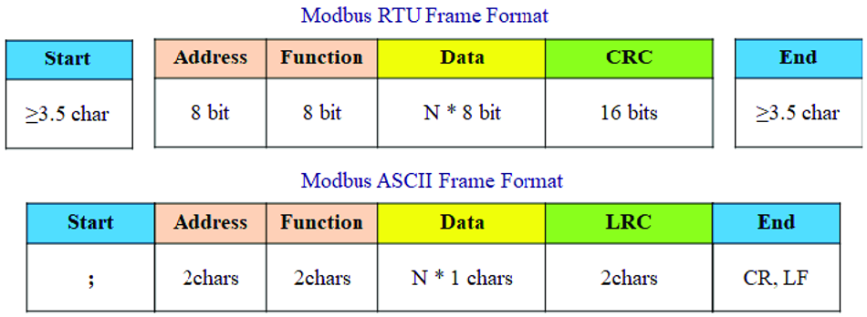
Modbus RTU vs. Modbus ASCII
When exploring the realms of industrial communication, Modbus RTU and Modbus ASCII emerge as distinctive variants of the Modbus protocol, with Modbus RTU known for its binary efficiency and Modbus ASCII celebrated for its human-readable ASCII representation. Understanding the distinctions between Modbus RTU and Modbus ASCII is crucial in selecting the appropriate variant for specific industrial applications.
Data Representation
Modbus RTU uses binary encoding, representing data in a compact and efficient manner using binary values (0s and 1s). This allows for faster transmission speeds and smaller message sizes. On the other hand, Modbus ASCII uses ASCII encoding, representing data using ASCII characters. While this offers human readability and ease of troubleshooting, it results in larger message sizes and slower transmission speeds.
Transmission Efficiency
Due to its binary format, Modbus RTU achieves higher transmission speeds and better efficiency in terms of bandwidth usage. It can transmit more data in a shorter amount of time. Modbus ASCII has slower transmission speeds and larger message sizes due to the additional overhead of ASCII encoding and decoding. This makes it less efficient in terms of bandwidth utilization.
Character Set
Modbus RTU does not rely on any specific character set since it uses binary encoding. Modbus ASCII uses a specific subset of the ASCII character set for data representation, with each character representing a binary value.
Error Detection
Modbus RTU utilizes CRC (Cyclic Redundancy Check) as an error-checking mechanism, ensuring data integrity during transmission. Modbus ASCII uses LRC (Longitudinal Redundancy Check) for error detection, but it is considered less robust than CRC.
The choice between Modbus RTU and Modbus ASCII depends on factors such as the specific application requirements, transmission speed needs, compatibility with existing systems, and the importance of human readability and troubleshooting capabilities.
Conclusion
In conclusion, Modbus RTU remains a reliable and widely adopted Modbus communication protocol in industrial automation systems. With its binary data representation, compact frame structure, and efficient transmission, Modbus RTU offers fast and reliable communication over serial interfaces. By leveraging the strengths of Modbus RTU, businesses can achieve seamless integration, real-time monitoring, and efficient control of devices in their automation networks.
Frequently Asked Questions (FAQs)
1. What is the difference between Modbus RTU and Modbus TCP/IP?
Modbus RTU is a serial communication protocol, typically using RS-232 or RS-485 interfaces, while Modbus TCP/IP is an Ethernet-based protocol that encapsulates Modbus frames within TCP/IP packets. Modbus RTU is often used in smaller, localized networks, while Modbus TCP/IP is suitable for larger, more complex networks with multiple devices and longer communication distances.
2. Can Modbus RTU and Modbus TCP/IP devices communicate with each other?
Yes, but a gateway or converter is required to translate between the two protocols. The gateway converts Modbus RTU frames to Modbus TCP/IP packets and vice versa, enabling seamless communication between devices using different protocols.
3. How many devices can be connected in a Modbus RTU network?
A Modbus RTU network can support up to 247 slave devices, each with a unique address. The master device communicates with the slave devices using their addresses, allowing for efficient and accurate data exchange.
4. What are the typical communication distances for Modbus RTU networks?
The communication distance for Modbus RTU networks depends on the serial interface used. For RS-232, the maximum distance is typically around 15 meters (50 feet), while RS-485 can support distances up to 1200 meters (4000 feet). However, these distances can be affected by factors such as cable quality, environmental conditions, and network topology.
5. How can I improve the reliability of my Modbus RTU communication?
To enhance the reliability of Modbus RTU communication, ensure proper wiring and grounding, use high-quality cables and connectors, and follow the recommended guidelines for network topology and device configuration. Additionally, implement error detection and handling mechanisms, such as CRC checks and timeout periods, to identify and resolve communication issues.
References
in this article
1. Introduction to Modbus RTU2. Modbus RTU Protocol Overview3. Modbus RTU Function Codes4. Modbus RTU Communication Modes5. Modbus RTU Error Handling6. Modbus RTU Troubleshooting7. Hardware Requirements8. Software Development Guidelines9. Timing and Throughput AnalysisModbus RTU vs. Modbus TCP/IPModbus RTU vs. Modbus ASCII12. Conclusion13. Frequently Asked Questions (FAQs)14. References