Understanding Baud Rate: Why is it Important?
A Comprehensive Guide to Understanding Factors, Challenges, Limitations, and Real-World Applications for Optimized Communication Speed and Reliability

10 Aug, 2023. 13 minutes read
The following table shows the most commonly used baud rates. The left portion of the table displays the speed and bit duration. The right part of the table shows the actual transmission speed. It assumes no parity and 8 data bits and one stop bit.
Transmission Speed
Real Transmission Speed
| Bauds | Bits/s | Bit duration | Speed | Actual speed | Actual byte duration | |
| 50 bauds | 50 bits/s | 20.000 ms | 6.25 bytes/s | 5 bytes/s | 200.000 ms | |
| 75 bauds | 75 bits/s | 13.333 ms | 9.375 bytes/s | 7.5 bytes/s | 133.333 ms | |
| 110 bauds | 110 bits/s | 9.091 ms | 13.75 bytes/s | 11 bytes/s | 90.909 ms | |
| 134 bauds | 134 bits/s | 7.463 ms | 16.75 bytes/s | 13.4 bytes/s | 74.627 ms | |
| 150 bauds | 150 bits/s | 6.667 ms | 18.75 bytes/s | 15 bytes/s | 66.667 ms | |
| 200 bauds | 200 bits/s | 5.000 ms | 25 bytes/s | 20 bytes/s | 50.000 ms | |
| 300 bauds | 300 bits/s | 3.333 ms | 37.5 bytes/s | 30 bytes/s | 33.333 ms | |
| 600 bauds | 600 bits/s | 1.667 ms | 75 bytes/s | 60 bytes/s | 16.667 ms | |
| 1200 bauds | 1200 bits/s | 833.333 µs | 150 bytes/s | 120 bytes/s | 8.333 ms | |
| 1800 bauds | 1800 bits/s | 555.556 µs | 225 bytes/s | 180 bytes/s | 5.556 ms | |
| 2400 bauds | 2400 bits/s | 416.667 µs | 300 bytes/s | 240 bytes/s | 4.167 ms | |
| 4800 bauds | 4800 bits/s | 208.333 µs | 600 bytes/s | 480 bytes/s | 2.083 ms | |
| 9600 bauds | 9600 bits/s | 104.167 µs | 1200 bytes/s | 960 bytes/s | 1.042 ms | |
| 19200 bauds | 19200 bits/s | 52.083 µs | 2400 bytes/s | 1920 bytes/s | 520.833 µs | |
| 28800 bauds | 28800 bits/s | 34.722 µs | 3600 bytes/s | 2880 bytes/s | 347.222 µs | |
| 38400 bauds | 38400 bits/s | 26.042 µs | 4800 bytes/s | 3840 bytes/s | 260.417 µs | |
| 57600 bauds | 57600 bits/s | 17.361 µs | 7200 bytes/s | 5760 bytes/s | 173.611 µs | |
| 76800 bauds | 76800 bits/s | 13.021 µs | 9600 bytes/s | 7680 bytes/s | 130.208 µs | |
| 115200 bauds | 115200 bits/s | 8.681 µs | 14400 bytes/s | 11520 bytes/s | 86.806 µs | |
| 230400 bauds | 230400 bits/s | 4.340 µs | 28800 bytes/s | 23040 bytes/s | 43.403 µs | |
| 460800 bauds | 460800 bits/s | 2.170 µs | 57600 bytes/s | 46080 bytes/s | 21.701 µs | |
| 576000 bauds | 576000 bits/s | 1.736 µs | 72000 bytes/s | 57600 bytes/s | 17.361 µs | |
| 921600 bauds | 921600 bits/s | 1.085 µs | 155200 bytes/s | 92160 bytes/s | 10.851 µs |
Introduction
Transmission speed is one of the most critical aspects of communication systems. The data transfer rate is pivotal in these systems' efficiency, accuracy, and performance. Baud rate is an essential concept in communication systems that determines the speed at which information is transmitted between devices.
In a communication system, several factors can affect the baud rates. For instance, signal-to-noise ratio, bandwidth, and modulation techniques are pivotal in determining or setting a baud rate for any system. This article will provide a comprehensive guide to baud rates, covering their definition, factors affecting them, their role in different communication systems, and how to calculate them.
What are Baud Rates?
The Baud rate represents the number of signal changes or symbols transmitted per second. It is measured in bauds (Bd) and is crucial for determining the speed and efficiency of data transmission between devices. A higher baud rate means faster transmission and reception of information between the communicating devices. Moreover, baud rates can determine the communication channel's transmission bandwidth and bit rate calculation.
The baud rate is often confused with the bit rate, but there is a clear distinction. Baud rates refer to the number of signal changes per second, while bit rate refers to the number of bits transmitted per second.
How Baud Rates are Important for Communication Systems
Baud rate plays a vital role in ensuring clear and accurate transmission of signals between communicating devices. Here are some critical reasons baud rates are valuable to any communication system.
Baud rate specifies the transmission speed over a serial line or serial interface.
Works are a tuning parameter to adjust network congestion.
Calculates the bit rate for a communication channel.
Determines the bandwidth of the communication channel.
Baud Rate and Bit Rate
To better understand the relationship between baud rate and bit rate, it is essential to consider the modulation techniques used in communication systems. Modulation is encoding digital information into an analog signal for transmission. One signal change or symbol represents one bit of information in simple modulation schemes, such as binary amplitude-shift keying (ASK) or frequency-shift keying (FSK). In these cases, the baud rate and bit rate are equal.
However, multiple bits can be transmitted with a single signal change in more advanced modulation techniques, such as quadrature amplitude modulation (QAM) or phase-shift keying (PSK). For example, in 16-QAM, each symbol represents four bits of information. In this case, the bit rate is four times the baud rate. The relationship between baud rate and bit rate can be expressed as:
Bit rate = Baud rate × Bits per symbol
Difference Between Baud Rate and Bit Rate
Baud rate refers to the number of signal changes or symbols transmitted per second, i.e.,
Baud rate = number of signal elements/ total time (in seconds)
while bit rate refers to the number of bits transmitted per second, i.e.,
Bit rate = number of bits transmitted/ total time (in seconds)
The primary difference lies in the amount of information each signal change or symbol can carry.
Understanding Bit Rate and Baud Rate in the Context of Modulation
In simple modulation schemes like binary ASK or FSK, one signal change represents one bit of information, equaling the baud rate and bit rate. However, in more advanced modulation techniques like QAM or PSK, multiple bits can be transmitted with a single signal change. This means the bit rate can be higher than the baud rate, depending on the modulation technique.
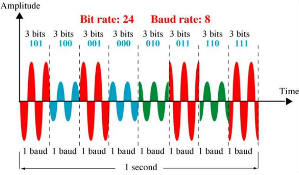
For example, in 8-PSK, each symbol can represent three bits of information. If the baud rate is 1,000 Bd, the bit rate would be 3,000 bps, as each symbol carries three bits. The relationship between baud rate and bit rate can be expressed as:
Bit rate = Baud rate × Bits per symbol
Image Source: slideserve.com
Based on the modulation techniques, the following table shows how bit rate and baud rate are related.
Modulation | Units | Bits/Baud | Bit Rate | Baud Rate |
ASK, FSK, 2-PSK | Bit | 1 | N | N |
4-PSK, 4-QAM | Dibit | 2 | 2N | N |
8-PSK,8-QAM | Tribit | 3 | 3N | N |
16-QAM | Quadbit | 4 | 4N | N |
32-QAM | Pentabit | 5 | 5N | N |
64-QAM | Hexabit | 6 | 6N | N |
128-QAM | Septabit | 7 | 7N | N |
256-QAM | Octabit | 8 | 8N | N |
Factors Affecting Baud Rates
Several factors can influence the baud rate in a communication system, including signal-to-noise ratio, bandwidth, and modulation techniques.
Signal-to-Noise Ratio
SNR is a critical factor that shows the ratio of the power of a signal to the power of background noise, typically measured in decibels (dB). A higher SNR indicates a cleaner signal with less noise, which allows for higher baud rates and more reliable data transmission.
The relationship between SNR and baud rate can be described using the Shannon-Hartley theorem, which states that the maximum achievable data rate (C) for a communication channel with a given bandwidth (B) and SNR is:
C = B × log2(1 + SNR)
As the SNR increases, the maximum achievable data rate increases, allowing for higher baud rates. For example, if the bandwidth is 1 MHz and the SNR is 100 (20 dB), the maximum achievable data rate would be approximately 6.64 Mbps. If the SNR increased to 1,000 (30 dB), the maximum achievable data rate would increase to approximately 9.97 Mbps.
Bandwidth
Bandwidth refers to the range of frequencies a communication channel can accommodate, measured in hertz (Hz). A higher bandwidth allows for more signal changes per second, enabling higher baud rates and faster data transmission.
The relationship between bandwidth and baud rate can also be described using the Shannon-Hartley theorem, as mentioned earlier:
C = B × log2(1 + SNR)
In this equation, C represents the maximum achievable data rate, B represents the bandwidth, and SNR represents the signal-to-noise ratio. The maximum achievable data rate increases with bandwidth, allowing for higher baud rates.
For example, reconsider the previous example having a maximum achievable data rate of 6.64 Mbps approx. If the bandwidth increased to 2 MHz while maintaining the same SNR, the maximum achievable data rate would increase to approximately 13.28 Mbps.
Modulation Techniques
Modulation is encoding digital information into an analog signal for transmission. Different modulation techniques can transmit varying amounts of information per signal change or symbol, directly impacting the baud rate.
Some standard modulation techniques include:
Amplitude-Shift Keying (ASK) - In ASK, the amplitude of the carrier signal is varied to represent different bits of information. Binary ASK, also known as On-Off Keying (OOK), is the simplest form of ASK, where one signal change represents one bit of information. In this case, the baud rate and bit rate are equal.
Frequency-Shift Keying (FSK) - In FSK, the frequency of the carrier signal is varied to represent different bits of information. Like binary ASK, binary FSK transmits one bit of information per signal change, equaling the baud rate and bit rate.
Phase-Shift Keying (PSK) - In PSK, the phase of the carrier signal is varied to represent different bits of information. Quadrature PSK (QPSK) is a common form of PSK, where each signal change represents two bits of information. In this case, the bit rate is twice the baud rate.
Quadrature Amplitude Modulation (QAM) - QAM is a more advanced modulation technique that combines amplitude and phase modulation. In QAM, each signal change can represent multiple bits of information, depending on the amplitude and phase levels used. For example, 16-QAM transmits four bits of information per signal change, making the bit rate four times the baud rate.
Baud Rates in Different Communication Systems
Baud rates are crucial in various communication systems, including serial, wireless, and optical communication. Understanding the role of baud rates in these systems and how they are determined is essential for optimizing their performance and achieving the desired data transmission speed and efficiency.
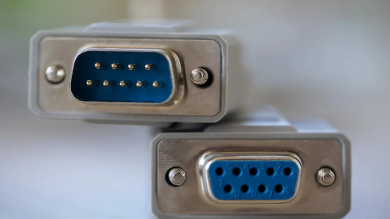
Serial Communication
Serial communication transmits data sequentially, one bit at a time, over a single communication channel. It is commonly used in computer peripherals, embedded systems, and industrial automation applications. In serial communication, the baud rate determines the speed at which data is transmitted between devices.
There are several types of serial communication, including
Universal Asynchronous Receiver/Transmitter (UART)
Serial Peripheral Interface (SPI)
Inter-Integrated Circuit (I2C).
There are different methods for determining the baud rate for each communication method, and it's generally based on the specific requirements and constraints of the application.
For example, in UART communication, the baud rate is determined by the clock frequency of the transmitting and receiving devices and the desired data transmission speed. The clock frequency is divided by a predetermined divisor to generate the desired baud rate. Standard baud rates in UART communication include 9600, 19200, 38400, and 115200 bps.
In serial communication systems, the choice of baud rate directly impacts the data transmission speed and reliability. For instance, increasing the baud rate in UART communication systems leads to larger baud rate errors which is a significant factor in the transmission system.
Wireless Communication
Wireless communication systems transmit data through the air using electromagnetic waves, such as radio frequency (RF) or infrared (IR) signals. These systems are widely used in mobile phones, Wi-Fi networks, and satellite communication applications. In wireless communication, the baud rate is a critical parameter determining the speed and efficiency of data transmission between devices.
Wireless communication standards have significantly evolved in the last few years. Some common wireless communication standards include Wi-Fi (IEEE 802.11), Bluetooth, and cellular networks (e.g., 4G LTE, 5G).
Further Reading: The Evolution of Wi-Fi networks: from IEEE 802.11 to Wi-Fi 6E
Various wireless communication standards and protocols have different methods for determining the baud rate, typically influenced by modulation techniques, signal-to-noise ratio, and bandwidth. For example, the baud rate in Wi-Fi communication is determined by the modulation technique used, the number of spatial streams (MIMO), and the channel bandwidth. Wi-Fi networks can use various modulation techniques, such as
Binary Phase-Shift Keying (BPSK)
Quadrature Phase-Shift Keying (QPSK)
Quadrature Amplitude Modulation (QAM).
Each modulation technique can transmit a different number of bits per symbol, which directly impacts the baud rate. Additionally, Wi-Fi networks can use different channel bandwidths (e.g., 20 MHz, 40 MHz, 80 MHz), which also affects the baud rate.
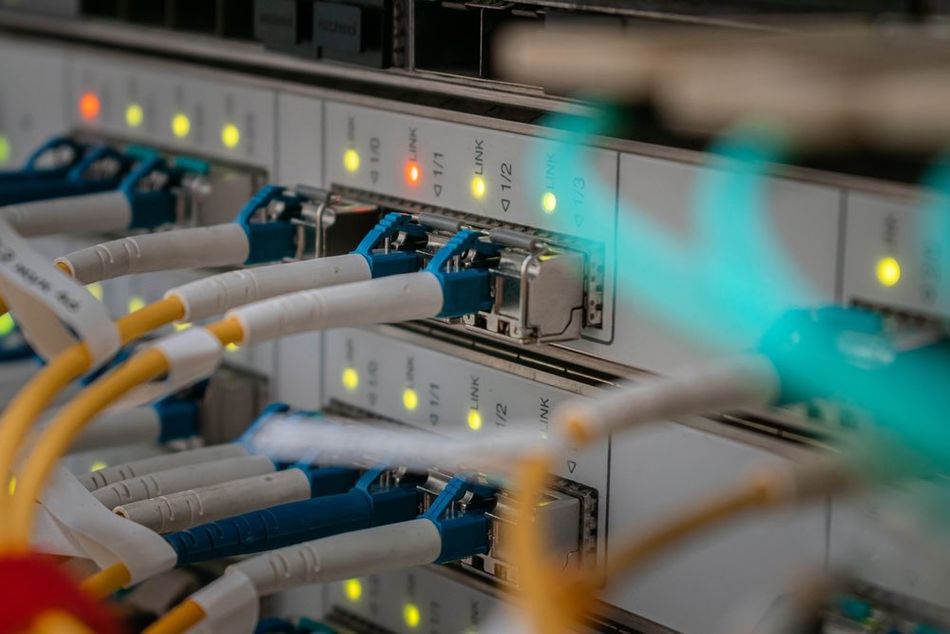
Optical Communication
Optical communication systems transmit data using light, typically in infrared or visible light signals. These systems are widely used in fiber-optic networks, free-space optical communication, and optical interconnects. In optical communication, the baud rate is a crucial parameter determining the speed and efficiency of data transmission between devices.
Optical communication systems use various modulation techniques to encode digital information into light signals, directly impacting the baud rate. Some standard modulation techniques used in optical communication include On-Off Keying (OOK), Phase-Shift Keying (PSK), and Quadrature Amplitude Modulation (QAM). Each modulation technique can transmit a different number of bits per symbol, which affects the baud rate.
For example, in Dense Wavelength Division Multiplexing (DWDM) fiber-optic networks, the baud rate is determined by the modulation technique and channel spacing. DWDM systems can transmit multiple data channels simultaneously, with each channel occupying a specific wavelength. The channel spacing, typically measured in gigahertz (GHz) or nanometers (nm), determines the number of channels transmitted within a given bandwidth. A higher channel spacing allows for more channels and higher baud rates.
Further Reading: Integrated Photonics: Comprehensive Guide to Optical Communication
How to Calculate Baud Rates
Calculating baud rates is an essential step in designing and optimizing communication systems. The process involves considering various factors, such as modulation techniques, signal-to-noise ratio, and bandwidth, to determine the optimal baud rate for a given application. Here is how engineers can calculate baud rates for different communication systems, including serial, wireless, and optical communication.
Baud Rate Calculation for Serial Communication
In serial communication systems, such as UART, SPI, and I2C, the baud rate is typically determined by the clock frequency of the transmitting and receiving devices and the desired data transmission speed. The clock frequency is divided by a predetermined divisor to generate the desired baud rate.
For example, in UART communication, the baud rate can be calculated using the following formula:
Baud rate = Clock frequency / Divisor
Suppose the clock frequency of a UART device is 16 MHz, and the desired baud rate is 9600 bps. To calculate the divisor, we can rearrange the formula:
Divisor = Clock frequency / Baud rate
Divisor = 16,000,000 Hz / 9600 bps ≈ 1667
In this case, the divisor is approximately 1667. The divisor may be rounded to the nearest integer value to achieve the closest possible baud rate to the desired value.
Baud Rate Calculation for Wireless Communication
In wireless communication systems like Bluetooth, Wi-Fi, and cellular networks, the baud rate must be calculated while considering factors like:
Modulation technique
Signal-to-noise ratio
Bandwidth
One approach to calculating the baud rate in wireless communication is to use the Shannon-Hartley theorem, which relates the maximum achievable data rate (C) to the bandwidth (B) and signal-to-noise ratio (SNR):
C = B × log2(1 + SNR)
In this equation, C represents the maximum achievable data rate, B represents the bandwidth, and SNR represents the signal-to-noise ratio. By knowing the bandwidth and SNR of a wireless communication system, we can estimate the maximum achievable data rate, which can be used as a reference for the baud rate.
For example, consider a Wi-Fi network using a 20 MHz channel bandwidth and an SNR of 30 dB (1,000). According to the Shannon-Hartley theorem, the maximum achievable data rate would be:
C = 20,000,000 Hz × log2(1 + 1,000) ≈ 199.5 Mbps
The actual baud rate is lower than the maximum achievable data rate thanks to error mechanisms, network overhead, and modulation techniques.
Wireless communication standards often define specific modulation schemes and data rates for different operating conditions..
Baud Rate Calculation for Optical Communication
In optical communication systems, such as fiber-optic networks and free-space optical communication, the baud rate is influenced by modulation techniques, signal-to-noise ratio, and channel spacing.One approach to calculating the baud rate in optical communication is to use the Nyquist formula, which relates the maximum achievable data rate (C) to the symbol rate (R) and the number of bits per symbol (n):
C = R × n
In this equation, C represents the maximum achievable data rate, R represents the symbol rate (equivalent to the baud rate in optical communication), and n represents the number of bits per symbol, determined by the modulation technique.
For example, consider a Dense Wavelength Division Multiplexing (DWDM) fibre-optic network using a 32-QAM modulation scheme. In 32-QAM, each symbol represents five bits of information (log2(32) = 5). If the symbol rate is 10 Gbaud (10 billion symbols per second), the maximum achievable data rate would be:
C = 10,000,000,000 symbols/s × 5 bits/symbol = 50 Gbps
Optical communication systems often use specific channel spacing and modulation schemes for different operating conditions, which can affect the actual baud rate compared to the maximum achievable baud rate.
Baud Rate Limitations and Challenges
Some fundamental limitations and challenges associated with baud rates include signal-to-noise ratio, bandwidth constraints, and modulation technique limitations.
Signal Interference and Noise
Increasing baud rates make the signal susceptible to signal interference. As a result, it experiences more noise and induces more errors during data transmission. Eventually, it requires error detection and correction mechanisms to retrieve accurate and original signals.
Long Distance Transmission
Higher baud rates might not be suitable for long-distance communication. As the distance increases, signal attenuation and propagation delays can affect the quality of the communication.
Bandwidth Limitations
The available bandwidth of the communication channel limits the baud rate. Higher baud rates require more bandwidth, which can become a limitation in scenarios where the available frequency spectrum is constrained.
Propagation Delay
The baud rate can affect the ability to accurately detect and interpret symbols, especially when the system has significant propagation delays due to long communication paths or latency.
Clock Synchronization
In serial communication, the transmitter and receiver must have synchronized clocks to interpret the symbols accurately. Achieving and maintaining clock synchronization at high baud rates can be challenging.
Hardware Design
Higher baud rates require more sophisticated hardware designs to ensure accurate symbol detection and transmission. This can lead to increased complexity and cost of the communication system.
Multipath Fading
In wireless communication, multipath fading occurs when signals take multiple paths to reach the receiver, causing interference and distortion. Higher baud rates can exacerbate the effects of multipath fading.
Compatibility
Baud rate compatibility must be ensured between communicating devices. If two devices operate at different baud rates, they won't be able to communicate effectively.
Conclusion
Baud rates are critical for the performance and efficiency of communication systems, including serial, wireless, and optical communication. By understanding how to calculate baud rates, affecting factors, limitations, and related challenges, it becomes easier for design engineers to optimize their systems and select compatible devices for specific communication applications.
Frequently Asked Questions (FAQs)
What is the difference between the baud rate and the bit rate?
Baud rate refers to the number of signal changes or symbols transmitted per second, while bit rate refers to the number of bits transmitted per second. The relationship between baud rate and bit rate depends on the modulation technique used, as different techniques can transmit varying amounts of information per signal change or symbol.
How do modulation techniques affect baud rates?
Modulation techniques directly impact the baud rate by determining the number of bits transmitted per signal change or symbol. Simple modulation schemes, such as binary ASK or FSK, transmit fewer bits per symbol, resulting in lower baud rates. More advanced modulation techniques like QAM or PSK can transmit more bits per symbol, allowing for higher baud rates.
What factors influence baud rates in communication systems?
Several factors can influence the baud rate in a communication system, including signal-to-noise ratio, bandwidth, and modulation techniques. Engineers must carefully consider these factors when designing and optimizing communication systems to achieve the desired baud rate and data transmission performance.
How can I calculate the baud rate for a given communication system?
Calculating the baud rate for a communication system involves considering various factors, such as modulation techniques, signal-to-noise ratio, and bandwidth. The Shannon-Hartley theorem and the Nyquist formula are two common approaches used to estimate the maximum achievable data rate, which can be used as a reference for the baud rate in a given system.
What are some common challenges and limitations associated with baud rates?
Some fundamental limitations and challenges associated with baud rates include signal-to-noise ratio limitations, bandwidth constraints, and modulation technique limitations. Engineers must carefully address these challenges to optimize communication systems and achieve the desired baud rates and data transmission performance.
References
Yichen Huang, Hao Lin, Di Zhanf, (2023). "Analysis of the baud rate of the UART to affects the data."
(PDF) Analysis of the baud rate of the UART to affects the data (researchgate.net)Si Ao Li, Hao Huang, Zhongqi Pan (2020). "Enabling Technology in High-Baud-Rate Coherent Optical Communication Systems"
Enabling Technology in High-Baud-Rate Coherent Optical Communication Systems | IEEE Journals & Magazine | IEEE XplorePPT - Figure 5-22 PowerPoint Presentation, free download - ID:3217330 (slideserve.com)