Understanding CAN Bus: A Comprehensive Guide
Born in the ‘80s, the CAN bus helps in carrying reliable electronic communication within your vehicles. This article delves into the basic principles, architecture, protocols, applications, and limitations of the CAN bus.

07 Nov, 2023. 18 minutes read
Introduction
Developed by Bosch in the 1980s, the Controller Area Network (CAN) bus is a popular communication protocol used in industrial and automotive applications. It was developed to improve data interchange between Electronic Control Units (ECUs), hence boosting system efficiency in vehicles. In 1993 [1], CAN was incorporated as an international standard communication system, ISO 11898, in industrial and automobile applications.
It is a message-based protocol [2], designed originally for multiplex electrical wiring within automobiles to save on copper, but it is also used in many other contexts. For an amateur, the CAN bus may seem confusing or complex, but its core principle is straightforward.
It is a communication method that allows vehicle systems and devices to communicate with each other, from the car's stereo to its ABS system. The CAN bus is the medium that exchanges instructions amongst the peer ECUs and other devices.
Suggested reading: Autonomous Vehicle Technology Report
Basic Principles of CAN Bus
The Controller Area Network (CAN) bus operates on a principle of decentralized networking, where all nodes (or devices) on the network are equal in their ability to transmit data. This is a departure from traditional networking models where a central master device controls communication.
CAN Bus Data Transmission
In a CAN network, any node can transmit data when the bus is free. This data is sent in the form of frames which contain the information being transmitted, as well as additional data for error checking and identification.
The CAN bus operates on a "broadcast" principle [3], meaning that all nodes receive all transmissions. Each node then decides whether to ignore the data or accept it based on the identifier in the CAN frame. This identifier is not a source or destination address, but rather a label indicating the content of the message. This means that the same message can be received and processed by multiple nodes, which is particularly useful in automotive applications where multiple systems may need the same data. This also means that a particular node cannot send a message to a specific node based on its address.
Data transmission in a CAN bus system is based on a differential two-wire interface (replacing complex wiring harnesses and connectors), which enhances noise immunity in the electrically noisy environment of a vehicle. The two wires, CAN-High (CANH) and CAN-Low (CANL), carry complementary signals. When a node transmits a dominant (0) signal, CAN-High goes to a higher voltage level than CAN-Low. Conversely, when a recessive (1) signal is transmitted, both CAN-High and CAN-Low are at the same voltage level [4].
The data is transmitted in frames, which consist of several fields. The most important of these are the identifier field and the data field. The identifier field contains the identifier of the message, which is used by receiving nodes to determine whether to accept the message. The data field contains the actual data being transmitted, which can be up to 8 bytes in standard CAN and up to 64 bytes in CAN FD (Flexible Data rate).
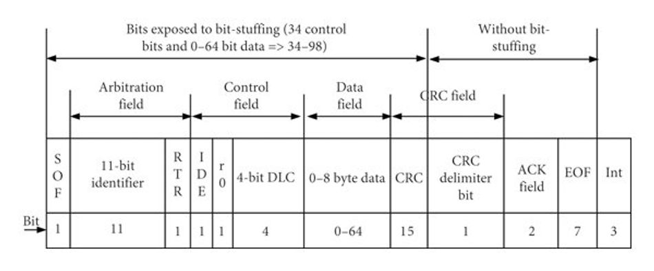
The significance of each field within the data frame is as follows:
| Field Name | Size (bits) | Description |
| Start of Frame (SOF) | 1 | The Start of Frame bit initiates the frame transmission and signals the beginning of a CAN message. It serves as a synchronization point for the receiving nodes. |
| Identifier (ID) | 11 or 29 | The Identifier field contains a unique message ID, which can be either 11 bits (Standard) or 29 bits (Extended). This ID differentiates between various messages on the CAN bus and helps prioritize their importance. |
| Remote Transmission Request (RTR) | 1 | The Remote Transmission Request bit indicates whether the frame is a data request (0) or a request for data (1). This bit informs receiving nodes whether to expect data or not. |
| Data Length Code (DLC) | 4 | The Data Length Code field specifies the number of data bytes included in the frame. It can range from 0 to 8, allowing for flexibility in the amount of data being transmitted. |
| Identifier Extension (IDE) | 1 | The Identifier Extension bit differentiates between Standard (0) and Extended (1) frames, indicating the length of the Identifier field. Standard frames use an 11-bit ID, while Extended frames use a 29-bit ID. |
| Data Field (Data) | 0-64 bits | The Data Field carries the actual data being transmitted. It can contain between 0 and 64 bits (0 to 8 bytes) of information, making it the primary content of the CAN frame. |
| Cyclic Redundancy Check (CRC) | 15 | The CRC field, or Cyclic Redundancy Check, is a 15-bit value used for error-checking purposes. It helps ensure data integrity during transmission by detecting any errors or corruption in the message. |
| Acknowledgment (ACK) | 1 | The Acknowledgment bit indicates whether the frame was successfully received. It plays a crucial role in confirming the reliable transmission of data between sender and receiver. |
| End of Frame (EOF) | 7 | The End of Frame field marks the conclusion of the CAN frame transmission. It is a sequence of bits used to signal that the message is complete and that the bus is available for the next transmission. |
Data transmission in a CAN bus is governed by the Carrier Sense Multiple Access with Collision Detection (CSMA/CD) principle. This means that each node monitors the bus (Carrier Sense) and transmits when the bus is free (Multiple Access). If two nodes transmit at the same time (Collision), the node with the lower identifier value continues transmitting while the other node stops. This is because dominant bits overwrite recessive bits on the bus, and lower identifiers (lower numerical value) have more dominant bits at the start of the CAN frame. This mechanism ensures that the highest priority messages (those with lower identifiers) are transmitted first [4][5].
Error Detection and Handling
One of the key features of the CAN bus system is its efficient error detection and handling capabilities. The system incorporates five methods of error detection, each designed to ensure the integrity of data transmission, as discussed below:
- Bit Monitoring: Each transmitting node in the CAN network system monitors the state of the bus while it is transmitting. If the bus state does not match the expected state, the node knows that an error has occurred.
- Frame Check Sequence (FCS): This field contains a cyclic redundancy check (CRC) value that is calculated based on the data in the frame. Each receiving node calculates its own CRC value and compares it to the received FCS. If the two values do not match, the node knows that an error has occurred.
- Acknowledgment Check: Each frame contains an ACK slot where all other nodes are expected to send a dominant bit to acknowledge receipt of the frame. If the transmitting node does not detect a dominant bit in the ACK slot, it knows that an error has occurred.
- Frame Format Check: Each frame has a specific format, including specific locations where dominant and recessive bits are expected. If a node detects a violation of this format, it knows that an error has occurred.
- Error Frame: When a node detects an error using any of the above methods, it transmits a special Error Frame that alerts all other nodes to the error. This causes all nodes to discard the current frame and wait for the retransmission of the correct frame.
When an error is detected, the node that detected the error automatically retransmits the frame. This continues until the frame is transmitted without errors. If a node detects too many errors, it goes into an Error Passive state where it only listens to the bus and does not transmit. If errors continue to occur, the node goes into a bus-off state where it is disconnected from the bus. This mechanism ensures that a faulty node does not disrupt communication on the bus.
CAN Bus Architecture
The architecture [6] of a CAN bus system is designed to facilitate efficient communication between multiple nodes. At its most basic, a CAN bus system consists of two lines, CAN-High (or CANH) and CAN-Low (or CANL), connected to all nodes in the system. These lines carry the differential signal that represents the transmitted data.
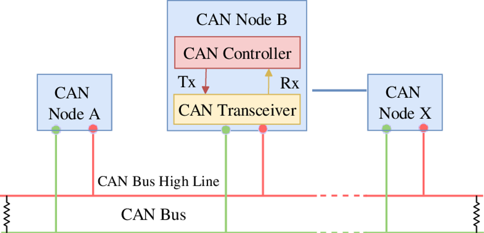
Fig 2. CAN Bus Architecture. Credits: Each node in the system has a Transceiver (or CAN transceiver), which interfaces with the bus lines, and a Controller (or CAN controller), which handles the framing of data and error checking. The CAN Transceiver is responsible for converting the digital signal from the CAN Controller into the differential signal on the bus, and vice versa. The Controller, on the other hand, is responsible for creating the frames that contain the data to be transmitted, as well as checking received frames for errors.
Nodes
In a CAN bus system, a node refers to any device that is connected to the bus and is capable of sending and receiving messages. Each node has its own Controller and Transceiver, allowing it to interface with the bus. Nodes can be anything, from simple sensors or actuators to complex devices like Engine Control Units (ECUs).
Each node in a CAN bus system transmits data whenever the bus is free. This data is sent in the form of frames, which contain the data, as well as an identifier that indicates the content of the message. All other nodes on the bus receive this frame and decide whether to accept it, based on the identifier value.
Nodes in a CAN bus system are also responsible for error detection. Each node checks received frames for errors using several methods, including bit monitoring and frame check sequences. If a node detects an error, it transmits an Error Frame that alerts all other nodes to the error.
Bus Lines
In a CAN bus system, the bus lines are the physical medium through which data is transmitted between nodes. There are two bus lines, CAN-High and CAN-Low, which carry complementary signals. These lines are typically twisted together to form a twisted pair, which helps to reduce electromagnetic interference and improve signal integrity.
The differential signaling used in CAN bus systems provides several advantages, as stated below:
- Common-Mode Noise: It improves noise immunity by ensuring that any noise picked up by the bus lines affects both lines equally. Since the receiving node is only interested in the difference between the voltages on the two lines, this common-mode noise is effectively canceled out.
- Reduced Magnetic Field: The use of complementary signals means that the current flowing in one line is equal and opposite to the current flowing in the other line. This reduces the net magnetic field generated by the current flow, further reducing electromagnetic interference.
The bus lines are terminated at both ends with resistors, typically 120 Ohms, which match the characteristic impedance of the lines. This termination is crucial for preventing signal reflections, which can cause errors in data transmission. In some cases, additional resistors known as biasing resistors may be used to ensure that the bus lines are in a known state when no nodes are transmitting.
The length of the bus lines and the number of nodes connected to them can impact the performance of the CAN bus system. Longer bus lines and more nodes can result in increased capacitance, which can slow down the rise and fall times of the signal. This, in turn, can limit the maximum data rate that can be achieved on the bus. To mitigate this issue, the CAN bus specification defines different data rates and maximum bus lengths, allowing system designers to choose the appropriate combination for their specific application.
Suggested Readings: Bus Topology: The Backbone of Simple Network Design
CAN Protocol
The CAN bus is recognized as an international standard for data communication. There are several protocols [7] used in CAN bus communication systems, each with its own set of features and capabilities. These protocols define the rules for data transmission, including frame formats, data rates, and error handling. Understanding the differences between these protocols is essential for selecting the appropriate one for a specific application.
The most widely used CAN bus protocols are CAN 2.0A, CAN 2.0B (also known as classical CAN), and CAN FD (Flexible Datarate). Each of these protocols builds upon the basic principles of the CAN bus system, adding new features and capabilities to meet the evolving needs of automotive and industrial applications.
CAN Protocols 2.0A and 2.0B
Classical CAN i.e. CAN 2.0A and CAN 2.0B are two closely related protocols that differ primarily in the length of their identifier fields. CAN 2.0A, also known as Standard CAN, uses an 11-bit identifier, while CAN 2.0B, or Extended CAN, uses a 29-bit identifier. This difference in identifier length (visible in Fig.1) has several implications for data transmission. Let’s touch on a few basic implications:
- Useful in complex systems: The longer identifier in CAN 2.0B allows for a greater number of unique message identifiers, which can be useful in complex systems with many nodes and data types. However, the longer identifier also increases the length of the frame, which can reduce the maximum data rate achievable on the bus.
- Finer Prioritisation: The longer identifier in CAN 2.0B provides more opportunities for the prioritization of messages. Since lower identifier values have the highest priority in the CAN bus system, the additional bits in the CAN 2.0B identifier allow for finer control over message priority.
- Flexibility: The use of different identifier lengths in CAN 2.0A and CAN 2.0B can impact compatibility between devices. While CAN 2.0B devices can generally communicate with CAN 2.0A devices, the reverse is not always true. This is because the longer identifier in CAN 2.0B frames can cause errors in CAN 2.0A devices that are not designed to handle them.
CAN Protocol FD
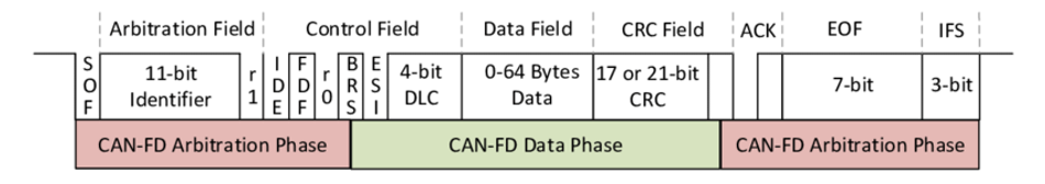
CAN FD (Flexible Data-rate) is a recent addition to the family of CAN bus protocols (2012), designed to address some of the limitations of CAN 2.0A and CAN 2.0B. The primary advantage of CAN FD is its ability to support higher data rates and larger data payloads, making it well-suited for modern automotive and industrial applications that require faster communication and more data throughput.
CAN FD achieves these improvements by introducing two key changes to the CAN bus protocol:
- Variable Data Rates: It allows for variable data rates during the transmission of a single frame. This means that the arbitration phase, where nodes compete for access to the bus, can occur at a lower data rate to ensure robust communication, while the data payload is transmitted at a higher data rate to improve throughput. This is particularly useful in electrically noisy environments, where a lower data rate can provide better noise immunity.
- Flexible Data Field Size: CAN FD increases the maximum size of the data field in a frame from 8 bytes in CAN 2.0 to 64 bytes. This larger data payload allows for more efficient transmission of data, as fewer frames are needed to transmit the same amount of information. This can be especially beneficial in applications where large amounts of data need to be transmitted quickly, such as high-resolution sensor data or software updates.
- Backward Compatibility: Despite these improvements, CAN FD maintains backward compatibility with CAN 2.0A and CAN 2.0B devices. This is achieved by using the same frame format as CAN 2.0B, with the addition of a new control field that indicates whether the frame is a CAN FD frame or a standard CAN 2.0B frame. This allows CAN FD devices to coexist with CAN 2.0A and CAN 2.0B devices on the same bus, although the higher data rates and larger data payloads of CAN FD will only be available when communicating with other CAN FD devices.
Suggested Readings: Modbus RTU: A Comprehensive Guide to Understanding and Implementing the Protocol
Suggested Readings: Understanding Modbus TCP-IP: An In-depth Exploration
CAN Bus Variants
The CAN bus functions at the Physical layer and Data-Link layer, just like RS-485. It is essential to realize that there are two widely used CAN bus specifications. When one hears the term "CAN bus," practically everyone immediately thinks of the ISO 11898-2 standard, also known as high-speed CAN. There are two variations of the CAN protocol, High-Speed CAN and Low-Speed CAN, each is designed to meet particular communication requirements.
High-speed CAN is intended for uses that need real-time and quick data interchange. The maximum data transfer rate is up to 1 Mbps. Reliable communication is ensured by High-Speed CAN's typical voltage values, which hover around 2.5V for recessive states and 3.5V for dominant states. This is especially important in noisy industrial and automotive situations.
Conversely, a fault-tolerant and low-speed variant of the CAN bus standard is ISO 11898-3 or Low-Speed CAN. It is appropriate for systems with less demanding data transfer rates, a maximum of up to 125 Kbps. Low-Speed CAN utilizes the same voltage levels as High-Speed CAN, which are roughly 2.5V for recessive states and 3.5V for dominant states. Unlike High-Speed CAN, the resistors here are dispersed over each node as opposed to being used as two termination resistors at the beginning and end of the bus.
Also, a low-speed fault-tolerant CAN can be designed in many different ways, such as a star-shaped bus, a linear bus akin to a high-speed CAN, or several star-shaped buses linked by a linear bus.
CAN Bus in Automotive Applications
The CAN bus has become an integral part of the modern automotive industry due to its efficiency and flexibility. It is used to facilitate communication between various Electronic Control Units (ECUs) and sensors within a vehicle, enabling the seamless integration of numerous subsystems. Some of the key applications of CAN bus in automotive systems include engine control, safety systems, body control, and infotainment systems. By using a common communication protocol, the CAN bus simplifies the wiring and reduces the complexity of the vehicle's electronic architecture, resulting in reduced weight, lower manufacturing costs, and easier diagnostics.
Suggested Readings: What is an Autonomous Vehicle: A Comprehensive Guide to its Engineering Principles and Applications
Engine Control
One of the primary applications of CAN bus in automotive systems is engine control. The Engine Control Module (ECM) is responsible for managing various aspects of the engine's operation such as fuel injection, ignition timing, and emissions control. To perform these tasks, the ECM needs to receive data from various sensors, such as the throttle position sensor, oxygen sensor, and crankshaft position sensor, and send commands to actuators, such as fuel injectors and ignition coils.
The CAN bus plays a crucial role in facilitating this communication between the ECM and other devices. By using a single bus to transmit data between the ECM and the various sensors and actuators, the CAN bus simplifies the wiring and reduces the number of connections required. This not only reduces the weight and complexity of the engine control system but also improves its reliability and maintainability.
Furthermore, the use of the CAN bus allows for real-time monitoring and control of the engine's operation. This enables the ECM to make rapid adjustments to the engine's parameters based on the data received from the sensors, ensuring optimal performance, fuel efficiency, and emissions control. Additionally, the CAN bus communication enables advanced diagnostic capabilities, allowing technicians to quickly identify and resolve issues with the engine control system.
Safety Systems
The CAN bus communication plays a critical role in the various operations of a vehicle's safety systems. These systems rely on the efficient exchange of data between sensors, actuators, and control modules to ensure the safety of the vehicle's occupants and other road users. Some of the key safety systems that utilize the CAN bus include Anti-lock Braking Systems (ABS), Electronic Stability Control (ESC), and Advanced Driver Assistance Systems (ADAS).
The Anti-lock Braking System (ABS) is designed to prevent wheel locking during heavy braking, which otherwise can lead to skidding and loss of control. The ABS control module receives data from wheel speed sensors and uses this information to modulate the braking force applied to each wheel. By using the CAN bus to transmit this data, the ABS control module can quickly and accurately adjust the braking force, ensuring optimal braking performance and vehicle stability.
Electronic Stability Control (ESC) is another safety system that relies on the CAN bus for communication. ESC is designed to detect and correct loss of traction or vehicle skidding by applying selective braking and adjusting engine torque. The ESC control module receives data from various sensors such as the steering angle sensor, yaw rate sensor, and wheel speed sensors, and uses this information to determine the appropriate corrective actions. The CAN bus enables rapid communication between the ESC control module and other devices, allowing the system to respond quickly to changing conditions and maintain vehicle stability.
Advanced Driver Assistance Systems (ADAS) encompass a wide range of safety features such as adaptive cruise control, lane departure warning, and collision avoidance systems. These systems rely on data from various sensors such as cameras, radar, and lidar, to monitor the vehicle's surroundings and provide assistance to the driver. The CAN bus is essential for transmitting this data between the ADAS control module and other devices, enabling real-time decision-making and control of the vehicle's safety systems.
By facilitating efficient communication between these systems, the CAN bus helps to improve overall vehicle safety and reduce the likelihood of accidents.
CAN Bus in Industrial Applications
In addition to its widespread use in automotive systems, the CAN bus has also found applications in various industrial settings. Its robustness, reliability, and flexibility make it an ideal choice for communication between devices in industrial automation and control systems. Some of the key industrial applications of the CAN bus include machine control, sensor networks, and distributed control systems.
Machine Control
Machine control is a critical aspect of industrial automation where precise coordination between various devices, such as motors, actuators, and sensors, is required to ensure efficient and accurate operation. The CAN bus is well-suited for this purpose, as it enables real-time communication between devices and allows the implementation of complex control algorithms.
In a typical machine control application, a central control module, often referred to as a Programmable Logic Controller (PLC), is responsible for coordinating the operation of various devices. The PLC receives data from sensors, such as position sensors, temperature sensors, and pressure sensors, and uses this information to determine the appropriate actions for the actuators, such as motors, valves, and solenoids.
The CAN bus facilitates the communication between the PLC and the various devices, allowing for rapid exchange of data and real-time control. By using a single bus for communication, the CAN bus simplifies the wiring and reduces the complexity of the machine control system, resulting in lower installation and low-cost maintenance. Additionally, the precise error detection and handling capabilities of the CAN bus ensure reliable communication, even in electrically noisy industrial environments.
The use of the CAN bus in machine control applications also enables advanced features, such as distributed control and remote monitoring. Distributed control allows for the decentralization of control tasks, with each device in the system capable of making decisions based on local data. This can improve the overall performance and flexibility of the system, as well as reduce the load on the central control module. Remote monitoring, on the other hand, enables operators to monitor and control the system from a remote location, improving efficiency and reducing downtime.
Sensor Networks
Sensor networks are an essential component of many industrial applications, providing real-time data on various parameters such as temperature, pressure, flow rate, and position. These networks often consist of multiple sensors distributed throughout a facility, each responsible for monitoring a specific parameter. The data collected by these sensors is then transmitted to a central control system, which uses the information to make decisions and control various processes.
The CAN bus is an ideal communication medium for sensor networks, as it offers several advantages over traditional point-to-point wiring.
First, the use of a single bus for communication simplifies the wiring and reduces the complexity of the network, resulting in lower installation and low cost maintenance. This is particularly important in large-scale industrial applications, where the number of sensors and the distances between them can be significant.
Second, the robust error detection and handling capabilities of the CAN bus ensure reliable communication between the sensors and the control system. This is crucial in industrial environments, where electrical noise and interference can cause errors in data transmission. The use of differential signaling and error-checking mechanisms in the CAN bus helps to minimize the impact of these issues, ensuring accurate and reliable data transmission.
Finally, the use of the CAN bus in sensor networks enables advanced features, such as distributed processing and remote monitoring. Distributed processing allows each sensor in the network to perform local data processing and decision-making, reducing the load on the central control system and improving the overall performance of the network. Remote monitoring, on the other hand, enables operators to monitor the status of the sensors and the data they are collecting from a remote location, improving efficiency and reducing downtime.
In summary, the CAN bus is a powerful and versatile communication medium that is well-suited for use in sensor networks in industrial applications. Its robustness, efficiency, and flexibility make it an ideal choice for ensuring reliable and accurate data transmission in these demanding environments.
Challenges and Limitations of CAN Bus
While the CAN bus offers numerous advantages in automotive and industrial applications, it is not without challenges and limitations. Some of the key issues that need to be considered when implementing a CAN bus system include data rate limitations, network size constraints, and electromagnetic compatibility.
- Data Rate: One of the primary limitations of the CAN bus is its data rate. Although CAN FD has improved data rates compared to CAN 2.0A and CAN 2.0B, it may still not be sufficient for some high-bandwidth applications such as high-resolution video streaming or large-scale data acquisition. In these cases, alternative communication protocols, such as Ethernet or FlexRay, may be more suitable.
- Limited Capacity: Another challenge associated with the CAN bus is the constraint on network size. The maximum length of the bus and the number of nodes that can be connected to it are limited by factors such as signal propagation delay, capacitance, and the electrical characteristics of the bus lines. As the number of nodes and the length of the bus increase, the performance of the system may degrade, resulting in reduced data rates and increased latency. To address this issue, system designers may need to consider using multiple interconnected CAN buses or alternative communication architectures.
- Electromagnetic compatibility (EMC): EMC is another important consideration when implementing a CAN bus system. The electrical noise generated by other devices in the environment can interfere with communication on the bus, leading to errors and reduced performance. To mitigate this issue, it is essential to follow best practices for EMC design, such as using twisted-pair cabling, proper grounding, and shielding of the bus lines. Additionally, the use of differential signaling in the CAN bus helps to improve noise immunity by canceling out common-mode noise.
Despite these challenges and limitations, the CAN bus remains a popular choice for communication in various industrial applications due to its reliability and flexibility.
Conclusion
The CAN bus is a powerful and versatile communication protocol that has become an integral part of modern automotive and industrial systems. Its robustness, efficiency, and flexibility make it an ideal choice for facilitating communication between various devices and subsystems. By understanding the basic principles, architecture, and protocols of the CAN bus, as well as its applications in automotive and industrial settings, engineers and system designers can effectively implement and optimize CAN bus systems to meet the requirements of their specific applications.
FAQ
1. What is the CAN bus?
The CAN bus (Controller Area Network) is a robust vehicle bus standard designed to allow microcontrollers and devices to communicate with each other's applications without a host computer. It is widely used in automotive and industrial applications for communication between various electronic control units (ECUs) and sensors.
2. What are the main differences between CAN 2.0A and CAN 2.0B?
The main difference between CAN 2.0A (Standard CAN) and CAN 2.0B (Extended CAN) is the length of their identifier fields. CAN 2.0A uses an 11-bit identifier, while CAN 2.0B uses a 29-bit identifier. This difference affects the number of unique message identifiers, message prioritization, and compatibility between devices.
3. What is CAN FD?
CAN FD (Flexible Data-rate) is a more recent addition to the family of CAN bus protocols, designed to support higher data rates and larger data payloads. It achieves these improvements by introducing variable data rates during the transmission of a single frame and increasing the maximum size of the data field in a frame.
4. How does the CAN bus handle errors?
The CAN bus incorporates several error detection and handling mechanisms, including bit monitoring, frame check sequences, acknowledgment checks, frame format checks, and error frames. These mechanisms ensure the integrity of data transmission and maintain system reliability.
5. What is a LIN bus?
The Controller Area Network (CAN) and Local Interconnect Network (LIN) protocols were both developed for the automotive industry. Later, LIN was added as a low-cost, simple alternative to the high-reliability, high-speed CAN protocol (up to 1 Mbit/s), which was built for the harsh environment of the automotive electrical bus.
References
[1] https://en.wikipedia.org/wiki/CAN_bus#History
[2] https://www.cl.cam.ac.uk/research/srg/han/Lambda/webdocs/an713.pdf
[3] https://copperhilltech.com/blog/controller-area-network-can-bus-message-broadcasting/
[4] https://www.engineersgarage.com/can-canopen-applications/
[5] https://www.eecs.umich.edu/courses/eecs461/doc/CAN_notes.pdf