Capacitors in Series: Theory, Design Considerations and Practical Implementations
This detailed guide explains the theory behind the capacitors in series, demonstrates how to calculate equivalent capacitance and voltage distribution, and highlights best practices for designing robust, high-voltage electronic systems.

21 Aug, 2025. 15 minutes read
Capacitors in Series
Introduction
Capacitors are fundamental to modern electronics! They store electrical energy, filter signals and stabilize power rails. In many designs, especially those involving high voltages or frequency selective networks, engineers must connect multiple capacitors in series. The series connection changes the effective capacitance and voltage distribution of the capacitor, allowing circuits to achieve higher voltage ratings or create precise impedance values.
This article provides a comprehensive analysis of capacitors in series! We start with the underlying physics, derive the equivalent capacitance and voltage relationships and discuss energy considerations. We then examine practical design issues, including voltage rating, leakage currents, balancing resistors and the impact of capacitor tolerances. The guide concludes with application examples of capacitors in series, such as high-voltage power supplies, AC coupling circuits, and high-pass filters.
Fundamentals of Capacitors
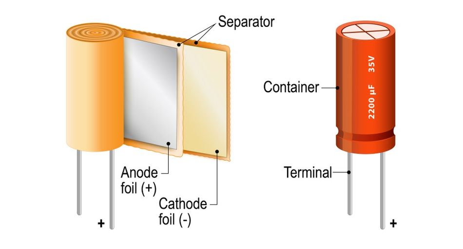
A capacitor consists of two conductive plates separated by an insulating material known as the dielectric. When a voltage is applied across the plates, electric charge accumulates on their surfaces, creating an electric field in the dielectric. [1] The fundamental relationship governing this behavior is:

where Q is the amount of charge (in coulombs), C is the capacitance value (in farads), and V is the applied voltage. The capacitance depends on factors such as the plate area, separation distance, and the permittivity of the dielectric. Increasing the plate area or using a thinner dielectric increases the capacitance value.
Capacitors store energy in the electric field, and the energy stored can be expressed in three equivalent forms:

This means that designers can calculate stored energy based on whichever variable set is most convenient: capacitance and voltage, charge and voltage, or charge and capacitance. For example, electrolytic capacitors often store high amounts of energy due to their large capacitance values, while small film capacitors store less but offer superior stability.
Charge Distribution and Voltage in Series
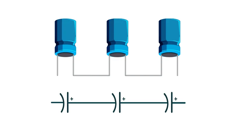
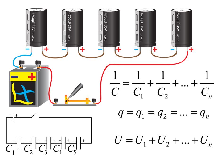
When capacitors in series are connected end-to-end, they share the same current path, forming a series circuit. Because there is no alternate route for electrons to travel, the amount of charge on each capacitor is identical. This leads to two critical properties of series capacitors:
Constant Charge: The individual capacitors in a series chain hold the same charge, regardless of their capacitance values.
Voltage Division: From the formula: V = Q/CV = Q/CV = Q/C, the voltage drop across each capacitor depends on its capacitance. The smaller capacitance results in a larger voltage drop, while a larger capacitance results in a smaller drop.
Applying Kirchhoff’s Voltage Law (KVL) to a series connection gives:

Substituting, Vi = Q / Ci and dividing by Q yields the equivalent capacitance formula for a series combination:

This indicates that the total capacitance of capacitors in series is always less than the capacitance of the smallest single capacitor in the chain. For example, with two capacitors of equal capacitance C, the equivalent capacitance is Ceq= C/2
In practical applications, such as high-voltage power supply filtering, series capacitors are often paired with resistors to ensure even voltage distribution, preventing overstress on any one capacitor.
The table below summarises the key formulas used throughout this article:
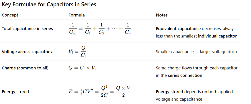
In summary, understanding capacitors in series equips engineers with the knowledge to optimize designs, balance voltage, and ensure reliable performance across diverse electronic and power system applications.
Recommended Reading: How to Discharge a Capacitor: A Comprehensive Guide for Engineers
Voltage Distribution and Stress
In a series combination of capacitors, the same charge passes through each device, but the voltage distribution is not uniform unless the capacitors are identical. The ratio of voltage drops across any two capacitors is inversely proportional to their capacitances:

This means that a capacitor with a smaller capacitance value will experience a larger voltage drop. For example, two identical capacitors in series (say, two 47 nF units across a 12 V supply) will each drop 6 V. However, if a 470 nF capacitor is paired with a 1 µF capacitor across the same 12 V, the larger 1 µF unit drops only 3.84 V, while the smaller 470 nF unit is stressed with 8.16 V. This imbalance arises because the equivalent capacitance is shared inversely between the devices, and the voltage ratio remains constant across frequency since the capacitive reactance follows:

Causes of Uneven Voltage Stress
Even when the applied voltage is within safe limits, individual capacitors may be pushed beyond their voltage rating.
The two major factors contribute to this issue:
1. Capacitance Tolerance
Real capacitors have tolerances typically in the ±10–20% range! This variation means that in practice, individual capacitances can differ significantly. For instance, three 450 V electrolytic capacitors rated at ±20% might vary by as much as 40% between the lowest and highest values. If such units are placed in a series connection across a 1200 V supply, the capacitor with the smallest capacitance could be forced to hold more than 514 V, already exceeding its specified voltage rating, even though the total voltage is technically within limits.
2. Leakage Current
All capacitors exhibit some degree of leakage current due to imperfections in the dielectric. In series capacitors, the leakage imbalance alters voltage distribution: the capacitor with the lowest leakage (highest effective resistance) will see a disproportionately higher share of the applied voltage. Over time, as capacitors age, leakage currents tend to increase unpredictably, leading to further instability in voltage division and potentially reducing system reliability.
Use of Balancing Resistors
To address these imbalances, engineers often place resistors across each capacitor. These are known as balancing resistors, and they provide a deliberate current path that minimizes the impact of leakage differences, ensuring a more even division of the applied voltage. Historically, design guidelines suggested choosing resistor values such that they conduct three to ten times the capacitor’s leakage current. While this rule of thumb provides a quick estimate, it also results in continuous power dissipation and, in poorly managed systems, can contribute to thermal stress.
A more accurate method is to size resistors based on the expected leakage current spread and the available voltage headroom. A commonly referenced design equation is:
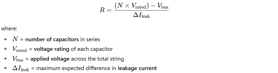
When selecting balancing resistors, engineers must also consider resistor power ratings, ensuring they can handle the continuous dissipation without overheating. Additionally, using resistors with tight tolerances (1% or better) and distributing them evenly across each capacitor avoids hot spots and enhances long-term reliability.
In high-voltage DC applications, such as power supply filters or supercapacitor banks, balancing resistors are indispensable. Without them, a single overstressed capacitor could fail, compromising the entire series circuit. By carefully balancing voltage distribution, engineers extend component life and ensure stable operation under both DC voltage and AC circuit conditions.
Equivalent Capacitance and Energy Storage
Total Capacitance
When capacitors are placed in a series connection, the total capacitance is always smaller than the smallest individual capacitor in the chain. This property is often used in circuit design to achieve non-standard capacitance values that are otherwise unavailable as a single component.
For example, combining a 10 µF capacitor with a 20 µF capacitor in series results in an equivalent capacitance of only 6.67 µF. Similarly, connecting 5 µF, 10 µF, and 20 µF capacitors yields a total of just 2.86 µF. For equal values, the relationship is simple:

where C is the capacitance of each capacitor, and n is the number of capacitors in series. Thus, three 15 µF capacitors connected in series provide a combined capacitance of 5 µF.
This property is particularly useful in filters, oscillators, and resonant circuits, where fine-tuned capacitance values are required. However, using multiple components introduces additional parasitic resistors and inductors, which can affect circuit behavior at higher frequencies. Engineers must carefully balance these trade-offs when deciding whether to connect capacitors in series or rely on a single precision capacitor.
Energy Storage in Series Networks
One of the most essential considerations in series capacitors is how they store energy. For a single capacitor, the energy stored in the electric field is given by:

when multiple capacitors are placed in a series combination, each capacitor holds energy based on its share of the applied voltage. Now, consider two identical capacitors (C) connected across a supply voltage (V). Each capacitor drops half the total voltage (V/2), so the total energy is:

This is only half of what would be stored if the same two capacitors were connected as parallel capacitors, which would yield:

Thus, while series capacitors provide the benefit of higher voltage ratings, they suffer from reduced energy storage. [2] In fact, for identical units, the energy is halved compared to a parallel connection at the same voltage.
This limitation becomes critical in applications such as defibrillators, camera flash circuits, or supercapacitor banks, where energy delivery is as important as voltage endurance. For instance, defibrillators must reliably deliver hundreds of joules of stored energy, often around 400 J, requiring banks of high-voltage electrolytic capacitors carefully sized for both total capacitance and voltage stress.
In high-energy systems, engineers often prefer a parallel combination of capacitors to maximize storage, and then arrange multiple parallel strings in series to meet the required DC voltage rating. This hybrid approach balances both energy stored and breakdown safety while minimizing parasitic losses.
High Voltage Applications and Voltage Multipliers
Increasing Voltage Rating
One of the most important reasons to use capacitors in series is to increase the effective voltage rating of the bank. If n identical capacitors, each rated for Vrated, are connected in a series combination, the theoretical total withstand voltage becomes:

In practice, however, tolerance mismatches and unequal leakage current distributions prevent perfect sharing of the applied voltage. To ensure reliability, engineers apply a derating factor, typically limiting the applied voltage to 60–80% of the theoretical maximum. This prevents any individual capacitor from exceeding its rating under worst-case conditions.
Such techniques are common in high-voltage power supplies, Cockcroft–Walton multipliers, X-ray generators, and even particle accelerators, where circuits routinely operate at hundreds of kilovolts. In these designs, series capacitors charge and discharge in timed sequences, gradually stepping up an AC input into a much larger DC output. Additionally, smoothing circuits use series connections to distribute stress evenly while reducing ripple and enhancing output stability.
Design Guidelines for High Voltage Series Banks
To safely implement high-voltage series capacitors, the following best practices are recommended:
Select Matching Components: Use capacitors from the same manufacturer batch to minimize tolerance variations. Pre‑measure capacitance values and group similar units together.
Add Balancing Resistors: Calculate resistor values based on expected leakage differences rather than arbitrary multiples. Ensure resistor power ratings safely dissipate continuous energy.
Derate Voltage: Avoid operating at the theoretical maximum; leave margin for imbalance and transients. For example, in a bank of four 450 V capacitors, the theoretical maximum is 1800 V. Still, designers often restrict operation to 1200–1400 V. This margin accounts for tolerance drift, transients, and ageing effects.
Monitor Temperature and Leakage: Ageing and heat increase leakage current. Provide adequate ventilation and avoid mounting balancing resistors near capacitors to prevent thermal runaway.
Use Protective Devices: In high‑energy applications, include fuses or varistors to protect against capacitor failure. High-voltage banks can release lethal energy; follow proper insulation and safety standards to prevent injury.
In summary, series capacitors enable higher voltage operation and power stability; however, careful design, derating, and protection are essential for safe and reliable high-voltage applications.
AC Coupling and High Pass Filtering
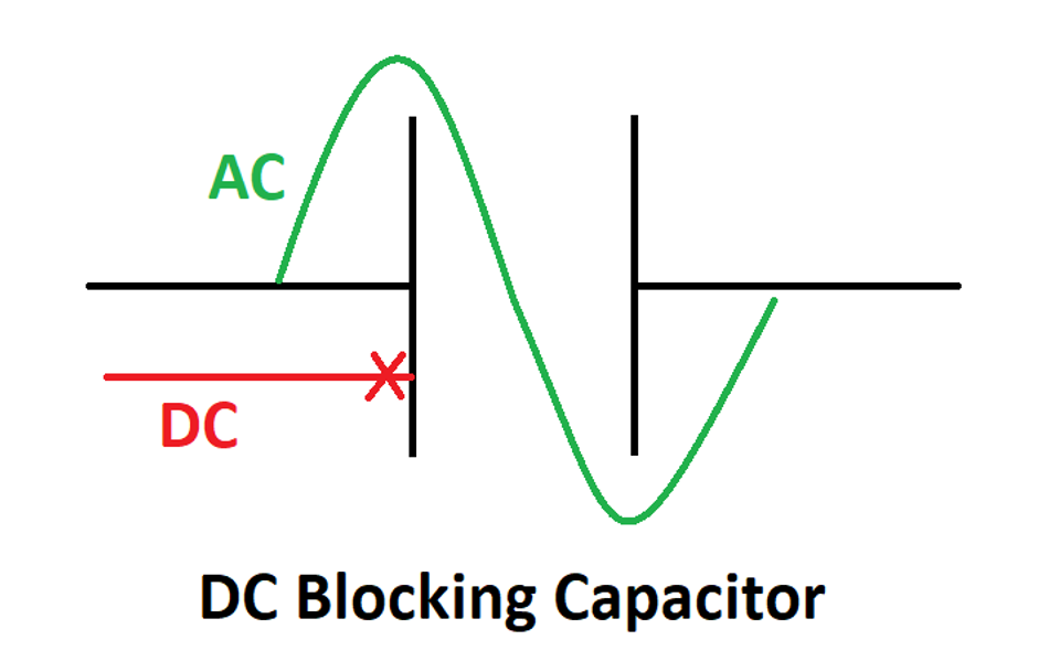
Series capacitors aren’t just for high voltages. In signal‑processing circuits, placing a capacitor in series with the signal path blocks DC and passes AC. This configuration, known as AC coupling, forms a first-order high-pass filter when combined with the input resistance of the receiving circuit.
AC coupling is most effective when used with DC-balanced codes, such as 8b/10b encoding, where the number of ones and zeros in any sequence is approximately equal. Because these signals contain little low-frequency energy, the high-pass filter removes the unwanted DC component without distorting the useful waveform. In practice, a series capacitor acts as a simple yet powerful DC-blocking capacitor.
The cutoff frequency of this high-pass filter depends on the capacitor and the input resistors of the next stage:
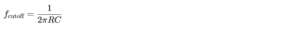
Here, R is the input impedance, and C is the coupling capacitor! At low frequencies, the reactance of a capacitor is high, effectively attenuating the signal. But, at high frequencies, reactance decreases, and the capacitor acts as a near short circuit, passing AC with minimal loss.
Practical Applications of Coupling Capacitors
Audio Systems: Coupling capacitors prevent DC bias from reaching speakers or amplifiers, reducing distortion, noise, and the risk of offset damage.
RF and Digital Communication: They isolate DC components in transmission lines, ensuring clean high-speed data transfer.
Power Amplifiers: Large-value electrolytic capacitors are used to block DC while passing low-frequency audio signals.
Choosing Capacitor Types for AC Coupling
Different capacitor technologies are used depending on the required capacitance value, frequency range, dielectric properties, and leakage current:
| Type | Advantages | Drawbacks | Suitable Applications |
| Ceramic (MLCC) | Small size, low ESR/ESL, inexpensive | Limited capacitance; microphonic effects | RF coupling, high‑speed digital signals |
| Tantalum | Stable capacitance, good volumetric efficiency | Higher ESR than ceramics, expensive, limited voltage | Audio coupling, low‑frequency analog signals |
| Aluminium Electrolytic | High capacitance, low cost | Large physical size, higher leakage, polarity sensitive | Power amplifier coupling, low‑frequency audio |
| Film (Polypropylene/Polyester) | Low distortion, stable over time | Large size, relatively expensive | Hi‑fi audio coupling, precision analog circuits |
Once using electrolytic capacitors for coupling, polarity must always be observed, as reverse bias can permanently damage the dielectric. For very high-frequency signals, ceramic capacitors are preferred because of their low parasitics and high self-resonant frequencies.
Example: AC Coupling High-Speed Differential Signals
Consider coupling a 1 Gb/s differential signal between two ICs, each with 100 Ω differential input impedance. Assuming the signal uses a DC-balanced code with the lowest spectral content around 100 kHz, we choose a cutoff frequency at least a decade lower (~10 kHz) to avoid distortion.

Thus, a standard 0.33 µF MLCC capacitor is suitable! Placing one series capacitor in each leg of the differential pair effectively blocks DC offsets between devices while preserving the differential eye diagram. Meanwhile, the DC bias for each receiver is provided through pull-up or pull-down resistors.
Recommended Reading: Decoupling Capacitors: Mastering Power Integrity in Electronic Design
Practical implementations and design examples
High-Voltage Supply with Series Electrolytic Capacitors
Consider designing a 600 V DC power supply using readily available 200 V electrolytic capacitors. To achieve the required voltage rating, we connect three capacitors (each 470 µF, 200 V) in series. The calculations proceed as follows:
- Equivalent Capacitance

The total capacitance is reduced by a factor of three compared to a single capacitor.
Voltage Distribution
Ideally, each capacitor holds 200 V. However, to account for tolerance spread and leakage current imbalance, the safe bus voltage is derated to ~500 V, or ≈83 % of the theoretical maximum (3 × 200 V).
Balancing Resistors:
If the maximum leakage current difference is 0.5 mA, the required resistor across each capacitor is:

The power dissipation is:

Using 1 W resistors ensures a sufficient safety margin and accounts for continuous operation.
Energy Storage

For reliability, designers also place bleeder resistors across the entire bank to discharge the capacitors when the supply is off. Enclosures, interlocks, and warning labels are essential for safety in high-voltage assemblies.
Creating non‑standard capacitance values
In RF and filter design, exact capacitance values are sometimes unavailable. Suppose an RF filter requires 7 nF, but only 10 nF and 15 nF capacitors are on hand. By placing the 10 nF and 15 nF capacitors in a series combination, we obtain:
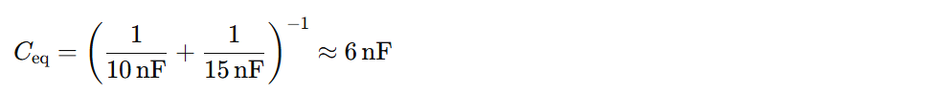
This value is close but slightly below the required 7 nF. Adding a 1 nF capacitor in parallel with the series pair increases the total capacitance to exactly 7 nF (6 nF + 1 nF). While such configurations increase component count, they are common in precision analog circuits where standard capacitor values or tolerances do not meet requirements.
High-Pass RC Filter for Sensor Interface
In low-frequency sensor interfaces, unwanted DC offsets can saturate the ADC input of a microcontroller. A simple solution is to insert a series coupling capacitor with a resistor to ground, creating a high-pass RC filter.
For example, if the sensor’s output impedance is 1 kΩ and we want a cutoff frequency of 1 Hz:

A 150 µF electrolytic capacitor approximates this value. Because the signal includes frequencies below 1 Hz, some low-frequency content will be attenuated. In critical systems, designers may opt for active level-shifting circuits or instrumentation amplifiers instead of simple AC coupling.
Series Capacitors in High-Power AC Networks
The concept of series capacitors extends beyond small circuits into large-scale AC power networks. In high-voltage transmission systems, series capacitor banks are used to reduce line reactance, improve voltage stability, and increase power transfer capability. By effectively compensating part of the inductive reactance of line, these banks raise the receiving-end voltage and reduce transmission losses.
Such banks often consist of dozens of high-voltage capacitors connected in series, enclosed in protective housings, and accompanied by safety devices such as spark gaps or metal oxide varistors (MOVs). These components protect the bank against fault currents and transients. Utilities deploy series compensation on long transmission lines to improve power factor, maintain system stability, and optimize the efficiency of national power grids.
Recommended Reading: Difference between Active and Passive Filters?
Choosing Capacitor Types and Managing Parasitics
When designing with series capacitors, engineers must carefully account for parasitic elements such as equivalent series resistance (ESR) and equivalent series inductance (ESL). Each individual capacitor contributes its own parasitics, and in a series combination, both ESR and ESL add linearly.
ESR (Equivalent Series Resistance): High ESR causes resistive heating when ripple current flows, reducing efficiency and shortening capacitor life. Excessive heating can also increase leakage current, accelerating degradation.
ESL (Equivalent Series Inductance): High ESL impairs performance in ac circuits, particularly at high frequencies, where inductive reactance dominates. This limits the ability of a capacitor to bypass fast transients or provide stable impedance in RF and high-speed digital designs.
For high-frequency decoupling and RF filters, designers typically choose multilayer ceramic capacitors (MLCCs), which offer very low ESR and ESL, as well as stable dielectric performance. For bulk energy storage at lower frequencies, larger electrolytic capacitors or film capacitors are more suitable, despite their higher parasitics, because their large capacitance value provides a significant amount of stored energy.
Polarity and Series Electrolytics
Electrolytic capacitors are polarized devices and must be connected with the correct orientation relative to the applied DC voltage. Reversing polarity can damage the dielectric layer, resulting in catastrophic failure. [3]
When connecting electrolytics in series, they are usually aligned plus-to-minus so that each device sees forward voltage stress. Designers must also ensure that no capacitor is forced into reverse bias due to tolerance or leakage imbalance. To mitigate risk:
DC Biased Systems: Always confirm that the applied voltage divides correctly across all units.
AC Coupling Applications: Where no DC bias exists, either use non-polarized electrolytics or connect two polarized capacitors back-to-back. This configuration cancels out reverse voltage but increases ESR and reduces the effective equivalent capacitance.
Minimizing Series Inductance and Loop Area
In high-frequency layouts, the physical arrangement of series capacitors has a significant impact on performance. Stray inductance and loop area can degrade signal integrity and shift the effective cutoff frequency of filters. Best practices include:
Short Leads and Traces: Keep capacitor leads as short as possible to reduce parasitic inductance.
Wider Copper Traces or Pours: Minimize resistive losses and improve current handling.
Close Placement: Position capacitors adjacent to each other when in a series connection, and rotate components to align their terminals for the shortest connection path.
Ground Planes: Use continuous planes beneath the capacitors to shield electric fields and reduce effective inductance.
Impedance Control for High-Speed Lines: When AC coupling differential signals (e.g., PCIe, Ethernet, SerDes), maintain trace width and spacing through the capacitor pads to preserve characteristic impedance and minimize reflections. [4]
In conclusion, selecting the right capacitor type and minimizing parasitics ensures reliable performance. Careful consideration of ESR, ESL, polarity, and layout optimizes efficiency, stability, and longevity in series capacitor designs.
Practical Tips for Working with Series Capacitors
There are several best practices for working with series capacitors.
The list below adapts these recommendations for professional engineers:
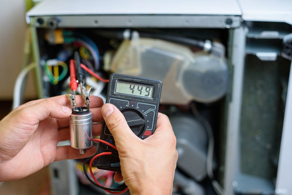
Voltage Rating Compliance – During prototyping, measure the voltage across each capacitor using a high-impedance probe to avoid circuit loading. Confirm that no device exceeds its rated voltage rating.
Capacitance Matching – Select capacitors with closely matched capacitance values and tight tolerances to achieve uniform voltage distribution.
Safety Procedures – Always discharge capacitors before handling. Even after disconnection, large capacitors can retain hazardous energy stored.
Pre-Charge Control – On initial energization, apply voltage gradually through a resistor to limit inrush current and prevent surge-induced stress.
Polarity Considerations – For electrolytic capacitors, observe correct polarity. In circuits with possible polarity reversal, use non-polarized types or back-to-back arrangements.
Regular Inspection – Periodically check for swelling, leakage, or discoloration. Replace any capacitor showing visible signs of dielectric degradation or overheating.
In summary, applying best practices with series capacitors—covering voltage, matching, safety, and polarity—ensures reliable operation, longer lifespan, and safer handling in both high-voltage power systems and precision electronic designs.
Advantages and Disadvantages of Series Connections
Series configurations bring both advantages and trade-offs. The table below summarizes key factors for circuit designers and hardware engineers:
| Feature | Benefits | Drawbacks |
| Voltage Handling | Higher total voltage rating; essential for high‑voltage supplies | Requires derating and balancing resistors to avoid over‑voltage stress |
| Capacitance Value | Enables creation of non‑standard capacitances; useful for filters | Total capacitance is reduced; increases impedance and decreases energy storage |
| Energy Storage | Supports high voltage without requiring high‑voltage single capacitors | Stores less energy compared with a single capacitor of equivalent voltage |
| Physical Size | May allow the use of smaller, lower‑voltage parts instead of one large component | More components increase footprint and assembly complexity |
| Voltage Distribution | When properly balanced, voltage is evenly shared | Mismatched capacitance or leakage can cause uneven voltage and failure |
In conclusion, series capacitor connections balance higher voltage capability with reduced capacitance and energy storage. Understanding their strengths and limitations helps engineers design safer, more efficient, and reliable electronic and power systems.
Recommended Reading: Power System Reliability Modeling: A Step Toward Resilient Data Centers
Conclusion
Series connections of capacitors are powerful tools for design engineers. They allow circuits to achieve voltage ratings beyond a single component’s limits, create non‑standard capacitance values and enable AC‑coupling and high‑pass filtering. However, the trade‑offs—including reduced capacitance, decreased energy storage and the risk of uneven voltage distribution—require careful attention. By applying the principles discussed here—matching capacitance values, using balancing resistors, derating voltages, and following safety procedures—engineers can confidently incorporate series capacitors into high-voltage supplies, communication interfaces, and precision filters.
For further exploration, readers should consult manufacturer application notes on electrolytic capacitor balancing, study high‑pass filter design for specific data codes and experiment with circuit simulation tools to observe voltage distribution and frequency response. A solid understanding of series capacitors enhances competence in power electronics, signal integrity and general circuit design.
Frequently Asked Questions (FAQ)
Q. What happens to the charge when capacitors are connected in series?
A. In a series circuit, all capacitors charge equally with the same electric charge. The amount of charge remains constant, governed by the applied voltage V, across the combined capacitor plates.
Q. Why does the total capacitance decrease when capacitors are in series?
A. Connecting capacitors in series effectively increases the distance between their plates. Since capacitance is inversely proportional to plate separation, the equivalent capacitance decreases. Mathematically, the reciprocal of each capacitance adds to give the reciprocal of the total, so the total is always less than the smallest individual value.
Q. When should I use capacitors in series instead of parallel?
A. Choose series capacitors for higher voltage ratings or non-standard capacitance values. Use parallel capacitors or parallel circuits for maximum energy storage, lower impedance, or when designing AC circuits that require enhanced reactance control.
Q. Can I mix capacitors with different values in series?
A. Yes, but uneven voltage distribution occurs in this case. The first capacitor or the second capacitor with the lowest value sees the greatest stress. For safety, verify the voltage rating, or use diodes for active equalisation.
Q. How do series capacitors affect AC and signal integrity in digital circuits?
A. They act as high-pass filters in AC circuits, influencing reactance and impedance. For best results, select microfarad-sized capacitors matching input inductors or transistors. Correct selection preserves electronic switches and automation stability.
References
[1] Lumen Learning. Capacitors and Dielectrics [Cited 2025 August 19]. Available at: Link
[2] MDPI. Estimation of Energy Storage Capability of the Parallel Plate Capacitor Filled with Distinct Dielectric Materials [Cited 2025 August 19]. Available at: Link
[3] Research Gate. Dielectric Materials for Advanced Applications [Cited 2025 August 19]. Available at: Link
[4] Altium. How to Use AC Coupling Capacitors in High-Speed PCBs [Cited 2025 August 19]. Available at: Link
in this article
1. Introduction2. Fundamentals of Capacitors3. Voltage Distribution and Stress4. Equivalent Capacitance and Energy Storage5. High Voltage Applications and Voltage Multipliers6. AC Coupling and High Pass Filtering7. Practical implementations and design examples8. Choosing Capacitor Types and Managing Parasitics9. Practical Tips for Working with Series Capacitors10. Advantages and Disadvantages of Series Connections11. Conclusion12. Frequently Asked Questions (FAQ)13. References