Thermistor: How It Works, Types, Equations and Uses
Read what a thermistor is, how NTC and PTC types work, the beta and Steinhart-Hart equations, key specs, applications and how to test one.

03 Oct, 2026. 17 minutes read
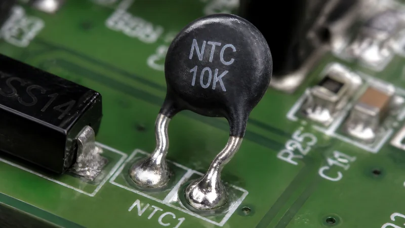
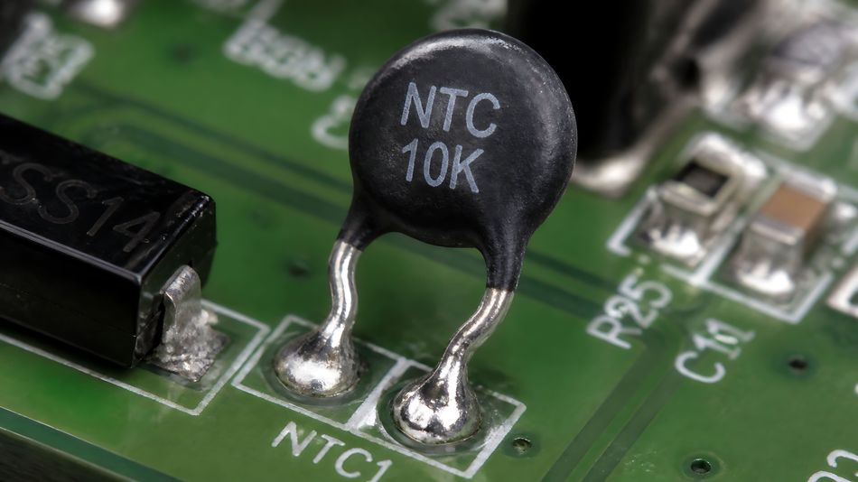
NTC Thermistor Soldered onto a Green Printed Circuit Board
Key Takeaways
Material and Temperature Response – Thermistor is a temperature-sensitive semiconducting ceramic resistor. NTC types lose resistance as they warm, while PTC types gain resistance steeply once they pass a reference transition temperature.
Sensitivity and Operating Range – NTC materials change resistance by about 2%/K to 6%/K, roughly ten times the temperature coefficient of pure metals, and measurement-grade NTC thermistors cover spanning ranges from −80°C to 300°C.
Nonlinear Response Modeling – The resistance curve is strongly nonlinear; while the beta parameter equation models narrow temperature bands, wider ranges require the Steinhart-Hart polynomial or calibration lookup tables.
Measurement Accuracy Constraints – Self-heating, lead wire resistance, and long-term drift dictate real-world accuracy. Selected, pre-aged thermistors operating between −20°C and 60°C can achieve drift rates under a few tenths of a millikelvin per year.
PTC Circuit Applications – PTC thermistors, including polymer resettable fuses (PPTCs), are widely used for overcurrent protection, motor-starting circuits, self-regulating heating elements, and dedicated temperature sensing.
Introduction
Thermistor (short for "thermal resistor") is a resistor designed to change its electrical resistance with temperature by a large, repeatable amount. Due to their high sensitivity, small size, and fast response, thermistors are widely used for accurate temperature measurement, monitoring, and control in electronic and industrial systems.
Unlike conventional resistors, a thermistor responds predictably to temperature changes, making it valuable in applications that require reliable thermal sensing. Thermistors fall into two main types: Negative Temperature Coefficient (NTC) and Positive Temperature Coefficient (PTC), each with a different resistance-temperature relationship.
This guide covers the two main thermistor types, the physics behind them, the equations that turn a resistance reading into a temperature, the specifications that matter on a datasheet, and how thermistors compare with resistance temperature detectors (RTDs) and thermocouples.
What Is a Thermistor?
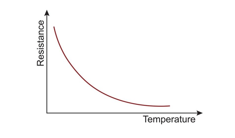
The thermistor is a resistor made from a semiconducting material, usually a sintered ceramic, whose resistance value is designed to depend strongly on temperature. [1] NTC thermistors are thermally sensitive semiconductor resistors that show a decrease in resistance as temperature increases.
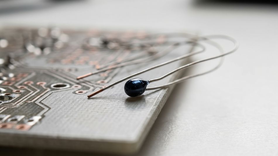
Resistance can change for two reasons: an external change in ambient temperature or internal heating from the current flowing through the device. All practical thermistor applications are built on this behavior. [2]
The Two Main Types of Thermistors: NTC and PTC
NTC (negative temperature coefficient) Thermistors: resistance falls as temperature rises. The coefficient is 2 %/K to 6 %/K, about ten times that of metals and about five times that of silicon temperature sensors.
PTC (positive temperature coefficient) Thermistors: resistance rises sharply once the component exceeds a defined reference temperature. That very high positive temperature coefficient above the reference point gives the part its name. [3]
Both belong to the broader family of thermally sensitive resistors, but they behave very differently, and each has its own IEC standard from Technical Committee 40.
IEC 60539-1:2022 is the generic specification for directly heated NTC thermistors, "typically made from transition metal oxide materials with semiconducting properties," and it sets standard terms, inspection procedures and test methods for these electronic components. [4]
IEC 60738-1:2022 does the same for PTC thermistors, which are "typically made from ferroelectric semiconductor materials." [5]
Two other families sit alongside the ceramic types: Polymer PTC (PPTC) devices, sold as resettable fuses, and silicon-based linear thermistors.
Polymer PTC (PPTC) Devices: These devices use a crystalline polymer containing conductive carbon black. Their resistance increases sharply when the device reaches its transition temperature. They are commonly used as resettable fuses for overcurrent protection. [6]
Silicon-Based Linear Thermistors: These thermistors use silicon and provide a more linear resistance response to temperature. For example, the TI TMP61 silicon temperature sensor has a typical temperature coefficient of approximately 6400 ppm/°C at 25°C. Such devices are used for temperature monitoring, thermal compensation, and threshold detection. [7]
Recommended Reading: What is an NTC Thermistor: Guide to This Temperature-Sensitive Resistor
How a Thermistor Works
NTC Thermistors: Semiconducting Metal Oxides
NTC thermistors are made from mixtures of metal oxides heated to high temperatures to form a polycrystalline ceramic. [1] The oxides of manganese, iron, cobalt, nickel, copper and zinc are used as the starting materials. The powders are milled, pressed into disks, chips or multilayer SMD parts, and sintered at 1000 °C to 1400 °C.
On their own, these oxides are electrical insulators. The mixture has intermediate electronic states that make the ceramic a semiconductor, so as temperature rises, more electrons gain enough thermal energy to become mobile charge carriers, and resistance falls. In many cases, the ceramic has a spinel crystal structure. [2]
Finished parts undergo a special ageing process. Without that step, solid-state reactions in the polycrystalline material could shift the resistance even at room temperature.
PTC Thermistors: The Curie-Point Switch
Ceramic PTC thermistors are made from doped polycrystalline barium titanate. Ceramics are normally good insulators, so manufacturers dope them with higher-valence ions than the crystal lattice; these supply free electrons and make the ceramic conductive.
The potential barriers form at the grain boundaries between crystallites. Below the ferroelectric Curie temperature, the material's high dielectric constant and polarization suppress those barriers; above it, the barriers grow, and the resistance rises by several powers of ten. [3]
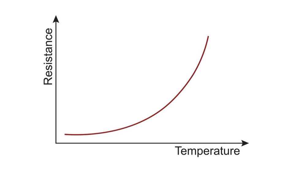
The reference temperature corresponds to the Curie point, where the zero-power resistance reaches twice its minimum value (Rref = 2 × Rmin). Below and above the steep region, resistance actually falls with temperature, so the positive coefficient applies only to the switching section of the curve.
Polymer PTC Thermistors (Resettable Fuses)
Polymeric PTC (PPTC) devices use a different mechanism. They use a conductive plastic made from a non-conductive crystalline polymer and highly conductive carbon black, where the carbon particles form conductive chains at room temperature.
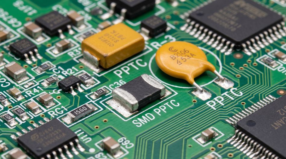
Under a fault, I²R heating raises the temperature until the polymer passes through a phase transformation from crystalline to amorphous and expands slightly. The carbon chains separate and resistance increases sharply. [6] The device stays latched in that state until the fault is cleared and power is removed; the polymer then re-crystallizes and the resistance returns to its original value.
Silicon Linear Thermistors
Some thermistors are built from silicon instead of ceramic. These devices typically exhibit a positive temperature coefficient (PTC) and provide a relatively linear change in resistance as temperature varies. Their predictable response can simplify temperature measurement and reduce the calibration required compared with conventional NTC thermistors.
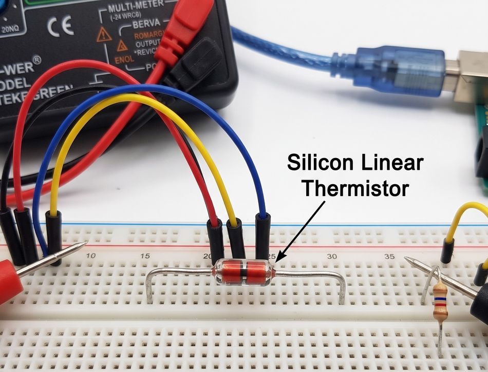
The TI TMP61 is a silicon-based PTC thermistor with nearly linear resistance change, 10 kω nominal resistance at 25 °C (±1% maximum from 0 °C to 70 °C), and a coefficient of 6400 ppm/°C at 25 °C. [7] Its operating range runs from −40 °C up to 150 °C, depending on the package. This part is positioned against NTC thermistors on linearity, calibration effort, resistor tolerance and sensitivity at high temperatures.
Recommended Reading: How are Semiconductors Made? Comprehensive Guide to Semiconductor Manufacturing
Thermistor Equations: Converting Resistance to Temperature
The Beta (B) Parameter Equation
Over a limited range, an NTC thermistor follows an exponential law:

Here, R(T) is the resistance at absolute temperature T in kelvin, T₀ is a reference temperature (often 298.15 K, or 25 °C), and c is a characteristic of the thermistor material. BIPM gives typical β values of 2,000 K to 6,000 K, and TDK quotes 2,000 K to 5,000 K for common NTC materials. [1][2]
B value is always defined between two temperatures. TDK mostly specifies B25/100, based on resistance values at 25 °C and 100 °C. [2]
Example: The BIPM's example thermistor has R(25 °C) = 10 kΩ and β = 3600 K. [1]
At 0 °C (273.15 K):

That matches the 30,196 Ω BIPM tabulates at 0 °C, and the same thermistor reads 3,929 Ω at 50 °C. The resistance changes by a factor of about 7.7 across that 50 °C span.
The exponential model describes only a restricted range around the rated temperature with sufficient accuracy. For wider ranges, you need a more complex equation such as Steinhart-Hart, or a tabulated curve.
The Steinhart-Hart Equation
The Steinhart-Hart equation adds a cubic term:

T is in kelvin, R is the thermistor resistance in ohms, and A, B and C are constants specific to the thermistor. Manufacturers may publish typical coefficients, or you can calibrate your own for better accuracy. [8]
To calibrate a thermistor for the Steinhart-Hart equation:
Select three calibration temperatures, typically with two near the limits of the intended operating range and one near its center. [8]
Measure the thermistor resistance at each temperature using an accurate reference thermometer.
Substitute the three resistance-temperature pairs into the Steinhart–Hart equation and solve the resulting three simultaneous equations for (A), (B), and (C).
Use the resulting coefficients within the calibrated temperature range. Extrapolation beyond this range can substantially increase measurement uncertainty. [1]
Example: Stanford Research Systems calibrated a thermistor that reads about 10 kΩ at 25 °C, using points at 5 °C (25 415 Ω), 25 °C (10 021 Ω) and 35 °C (6 545 Ω). That gives A = 1.1384 × 10⁻³, B = 2.3245 × 10⁻⁴ and C = 9.489 × 10⁻⁸. [8] Applying those coefficients to a reading of 15,000 Ω, where ln(R) = 9.6158:
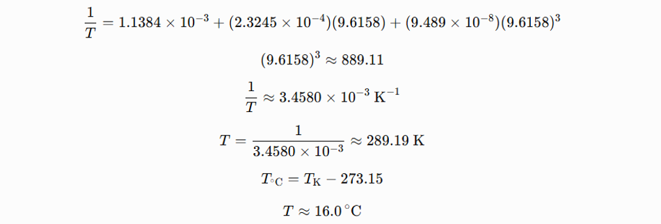
The equation has a notable point. The recommendation by Steinhart and Hart in 1968 rested on a numerical error: that, in practice, the equation is only sometimes better than an ordinary three-term fit, and that a four-term version is always more accurate. In high-accuracy work, the number of terms depends on the temperature range and required accuracy, most commonly two or four. [1]
For example:
The two-point calibration over 15 °C to 25 °C targets about 0.1 °C accuracy, with combined standard uncertainties of 0.074 °C and 0.081 °C at the calibration points.
The four-term calibration over 0 °C to 50 °C against a standard platinum resistance thermometer reaches combined standard uncertainties of 0.85 mK to 2.0 mK at the calibration points.
Lookup Tables
Not every thermistor-based system calculates temperature using an equation. Many designs instead use a resistance-temperature (R/T) lookup table supplied by the thermistor manufacturer.
These tables contain experimentally determined resistance values corresponding to specific temperatures across the device's specified operating range. Some manufacturers provide R/T data at 1 °C intervals, allowing the controller or software to determine temperature directly from measured resistance. [2]
Lookup tables are particularly useful in embedded systems because they can reduce computational requirements and account for the actual resistance-temperature characteristics of a specific thermistor. Firmware can also interpolate between adjacent table entries when greater temperature resolution is required.
Sensitivity and Nonlinearity
The sensitivity (S) of a thermistor is its fractional change in resistance per degree:

NTC thermistors range from about −0.03/°C to −0.05/°C at room temperature. That is about ten times the sensitivity of a platinum resistance thermometer, whose coefficient is about 3.85 × 10⁻³/°C. [1]
Because β/T² shrinks as temperature rises, the sensitivity falls across the range:
| Temperature | Resistance (10 kΩ, β = 3600 K) | Sensitivity (S) |
| 0.00 °C | 30,196 Ω | −0.0483 /°C |
| 16.67 °C | 14,149 Ω | −0.0429 /°C |
| 33.33 °C | 7,202 Ω | −0.0383 /°C |
| 50.00 °C | 3,929 Ω | −0.0345 /°C |
In practice, resolution is best at low temperatures and relatively poor at higher ones, where resistance changes less per degree. [8] Linearizing circuits help: a simple one-resistor circuit keeps linearity within 0.1 °C over about 20 °C, and multiple thermistor-resistor networks stay within 0.02 °C over ranges up to 100 °C. [1] The most accurate wide-range measurements still come from measuring resistance directly, for example with a digital multimeter.
Key Thermistor Specifications
Once selecting a thermistor for a specific application, consider several electrical and thermal specifications.
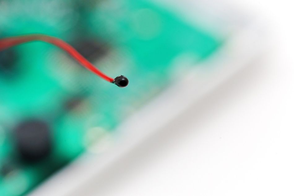
The most important parameters include:
Rated Resistance (R25): The resistance of a thermistor measured under zero-power conditions at the rated temperature, usually 25 °C. The specified resistance tolerance indicates how much the actual value can vary from the nominal resistance.
B Value (B25/100): The B value describes the relationship between a thermistor's resistance and temperature. It represents the slope of the resistance-temperature curve and depends primarily on the material used to manufacture the thermistor. [2]
Temperature Coefficient (α): This indicates the relative change in resistance for each degree of temperature change. For NTC thermistors, the coefficient is negative, typically ranging from approximately −2%/K to −6%/K.
Dissipation Factor (δth): This specifies the amount of power required to increase the thermistor's body temperature by 1 K under specified environmental conditions. It is usually expressed in mW/K and depends strongly on the surrounding medium and mounting conditions.
Thermal Time Constant (τ): The thermal time constant indicates how quickly a thermistor responds to a change in temperature. It is defined as the time required for the thermistor to reach approximately 63.2% of the total temperature change following a step change in temperature.
Maximum Power (P25): The maximum power the thermistor can dissipate at an ambient temperature of 25 °C under specified conditions. Operating near this limit can cause significant self-heating, which may affect temperature measurement.
Operating Temperature Range: This defines the minimum and maximum temperatures within which the thermistor can operate reliably. The range depends on factors such as the sensing material, construction, and encapsulation.
PTC-Specific Parameters: PTC thermistors may also specify parameters such as reference temperature, rated current, and switching current. These values describe the temperature at which the resistance changes significantly and the current levels associated with normal and switching operation. [3]
Recommended Reading: Linear vs Switching Power Supply: Understanding the Differences
Self-Heating and Other Error Sources
Self-Heating
To read a thermistor, you have to pass current through it, and that current heats it. The resulting error is proportional to the dissipated power and to the thermal resistance between the thermistor and its surroundings.
One example runs 10 µA through the 10 kΩ thermistor at 0 °C, where it measures 30,196 Ω, with a dissipation constant of 8 mW/°C in stirred oil. The self-heating error is about 0.4 mK. [1] The arithmetic behind it: (10 µA)² × 30 196 Ω is about 3 µW, and 3 µW divided by 8 mW/°C is about 0.4 mK. Raise the current to 1 mA at 25 °C and the same part dissipates 10 mW, which at 8 mW/°C already means an error of about 1.25 °C.
The environment changes the picture. Thermal resistance can vary by more than a factor of 100 between still air and stirred water. [1][2] The constant-current excitation dissipates the most power at low temperatures (I²R), while constant-voltage excitation dissipates the most at high temperatures (V²/R). It is better to keep the applied power as low as possible.
Lead Resistance, Stray Heat and Insulation
Lead Resistance: Two-wire measurement is usually fine because thermistor resistance is high. It becomes a problem at higher temperatures, when resistance is low: BIPM's example shows a 1 Ω lead resistance causing a 7.4 mK error at 50 °C. [1] High-accuracy calibration uses a 4-wire measurement to eliminate lead effects.
Stray Heat: High thermal resistance to the surroundings makes thermistors sensitive to infrared radiation and heat conducted along the lead wires, especially when measuring air or surface temperatures. Thermally anchoring the leads is recommended.
Insulation Resistance: Resistance often exceeds 10 MΩ at low temperatures, so poor lead insulation can shunt the measuring current.
Stability and Drift
The intrinsic causes of instability include cracking of the thermistor body during temperature cycling, drift at high temperatures from ingress of atmospheric gases, crystallographic changes, and changing contact resistance at the leads. Glass-encapsulated bead thermistors are the most stable, and parts in the 2 kΩ to 10 kΩ range also appear to be the most stable.
Aging usually shows up as a resistance increase or a change in B value, and unprotected, non-glass-encapsulated parts can exchange oxygen with their environment. [2]
Thermistors vs RTDs vs Thermocouples
Resistance Temperature Detectors (RTDs) and Thermocouples are the main alternatives to thermistor temperature sensors.
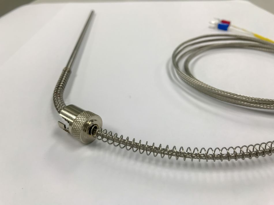
Thermistors offer very high sensitivity, small size (some under 0.2 mm) and time constants as short as a few milliseconds, but they are highly nonlinear, cover a limited temperature range, and risk self-heating from the sensing current. [1]
| Sensor | Temperature Range | Sensitivity and Linearity |
| NTC Thermistor (Glass-encapsulated) | −80 °C to 300 °C | −0.03/°C to −0.05/°C at Room Temperature; Strongly Nonlinear |
| Silicon Linear Thermistor (TI TMP61) | −40 °C to 150 °C | +6400 ppm/°C at 25 °C; Nearly Linear |
| Platinum RTD (IEC 60751) | −200 °C to 850 °C | Nearly 3.85 × 10⁻³/°C |
| Type K Thermocouple | −270 °C to 1,372 °C | Output is a Thermoelectric Voltage (54.886 mV at 1,372 °C), not a Resistance |
Put simply, a thermistor gives the highest resolution over a moderate range, a platinum RTD extends to 850 °C, and a type K thermocouple reaches well beyond that.
Recommended Reading: Thermistor vs Thermocouple: Which Temperature Sensor Suits Your Engineering Needs?
Thermistor Applications
Temperature Measurement and Temperature Control
Battery Charging: Lithium-ion chargers such as the BQ25176J monitor battery temperature through an NTC thermistor on a dedicated pin; TI recommends a 10 kω 103AT-2 part. The charger follows the JEITA profile: normal charging from 10 °C to 45 °C, 20 % of the set current from 0 °C to 10 °C, half current (and a 4.1 V limit for charge voltages set above 4.1 V) from 45 °C to 55 °C, and no charging below 0 °C or above 55 °C. [10]
3D Printers: Thermistors are the most commonly used temperature sensors in RepRap printers: one senses the hot end, and often a second senses the heated bed. These are typically 100 kΩ NTC parts read through a voltage divider, and the wiki's lookup tables assume a 4.7 kΩ resistor on the supply side.
HVAC and Appliances: HVAC equipment and thermostats are among the applications for a linear thermistor. [7] Other everyday examples include coil and room sensors in an air conditioner, tank sensors in water heaters, and engine coolant or oil temperature sensors in vehicles.
Flow, Level and Vacuum Sensing: The self-heated dissipation factor in a thermistor rises in moving air or liquid and falls in vacuum, so NTC parts can sense gas or liquid flow rate, liquid level and vacuum, and support gas analysis. [2]
Precision Thermometry: Thermistor measurements can reach accuracies approaching 1 mK without expensive AC bridges, and parts interchangeable to 0.05 °C are available. [1] Within 20 °C to 60 °C, BIPM notes that their stability, sensitivity and simple instrumentation give short-term accuracy approaching that of a standard platinum resistance thermometer at much lower cost.
Inrush Current Limiting
Power NTC thermistors use self-heating deliberately. Inrush current limiters and liquid level sensors operate in the falling portion of the NTC voltage/current curve, where resistance decreases more rapidly than current increases. [2] In an inrush current limiter, the cold thermistor's resistance limits the surge when a power supply is switched on; current then heats the thermistor and its resistance drops.
TDK's inrush current limiter examples include an 8 Ω ± 20% disk with an 11.5 mm nominal diameter and a 4 Ω ± 20% disk at 13 mm. [9]
Overcurrent and Circuit Protection
Ceramic PTC thermistors act as resettable fuses against current overload and as short-circuit protection in motors. Their datasheets list two currents: at or below the rated current IR, the part stays in low-resistance mode; at or above the switching current IS, it reliably switches to high-resistance mode.
Here, two wiring rules matter for circuit protection design. Never connect overcurrent-protection PTCs in series to raise voltage capability, and count two in parallel as only 1.8 times the rated current of one, because of resistance tolerances. Polymer PTC resettable fuses do the same job for overcurrent protection and reset once the fault is cleared and power is removed. [6]
Heating, Motor Starting and Delayed Switching
PTC thermistors also serve as self-regulating heating elements, as motor starters in refrigerator compressors, and for delayed switching in switch-mode power supplies and lamp ballasts. [3] The self-regulation comes from the curve itself: if ambient temperature rises or heat transfer to the surroundings drops, the PTC heats further and its current falls considerably.
Recommended Reading: What Is an NTC Thermistor: Unveiling the Temperature-Sensitive Powerhouse
How to Choose a Thermistor
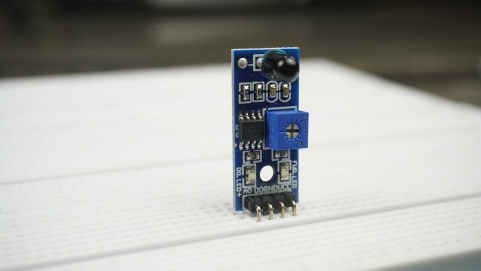
Follow these steps to choose a thermistor:
Define the Range and Accuracy: Measurement-grade NTC thermistors cover about −80 °C to 300 °C; beyond that, look at platinum RTDs or thermocouples.
Pick the Type: Use NTC for measurement and inrush limiting, PTC for protection, heating and switching, and a silicon linear part when you want a simple conversion. [2][3][7]
Choose the Rated Resistance: Match R25 to your circuit and range. BQ25176J charger calls for 10 kΩ, RepRap printers typically use 100 kΩ, and BIPM finds 2 kΩ to 10 kΩ parts the most stable. Remember that resistance gets very high when cold and low when hot, where lead resistance starts to matter.
Check Tolerance and Interchangeability: Resistance tolerance is specified at one temperature, usually 25 °C, and the B-value tolerance widens the spread away from it. If you need to swap parts without recalibrating, parts interchangeable to 0.05 °C exist.
Match the Thermal Specifications to the Environment: Check the dissipation factor and time constant for your medium; smaller parts respond faster but tolerate less load.
Choose the Encapsulation: Glass-encapsulated thermistors are the most stable and reach about 300 °C; epoxy types top out around 150 °C.
Plan the Conversion and Calibration: Use the beta equation for narrow ranges, Steinhart-Hart (a four-term fit), or the manufacturer's R/T table for wide ones.
How to Test a Thermistor
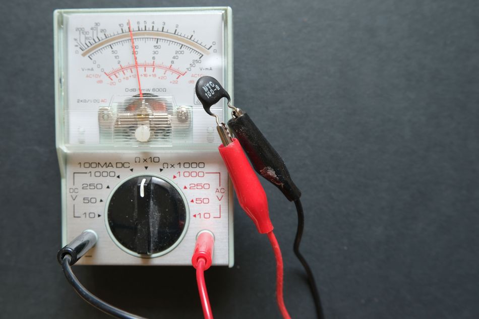
Follow these steps to test a thermistor:
Isolate It: Power down the circuit and disconnect at least one lead so other components don't load the measurement.
Measure at a Known, Stable Temperature: Read the resistance value with a multimeter while the thermistor sits at a known temperature. Keep the measuring current low, so you read the zero-power resistance rather than a self-heated value.
Compare with the Datasheet: A 10 kΩ ± 1 % part should read 9.9 kΩ to 10.1 kΩ at 25 °C. [2] At other temperatures, use the manufacturer's R/T table and allow for the B-value tolerance.
Check a Second Temperature: Ice water gives a convenient 0 °C point; wrap the sensor to keep it dry. [8] The 10 kΩ, β = 3600 K NTC thermistor should read about 30 kΩ at 0 °C. The resistance should move in the expected direction: up when an NTC is cooled, and sharply up when a PTC is heated past its reference temperature.
Interpret the Result: The reading far above the rated value, or over range, points to an open circuit, and one far below it to a short. Reading that is plausible but consistently offset points to drift.
What Happens When a Thermistor Goes Bad?
Thermistor failures fall into three broad patterns, and each one misleads the controller differently:
Open Circuit: The cracked element or broken lead gives infinite resistance. NTC then reads as extremely cold. Marlin 3D printer firmware shuts the printer down with a MINTEMP error, which it says "means your thermistor has disconnected or become an open circuit." Temperature cycling is a known cause of body cracking. [1]
Short circuit: Shorted leads look like an extremely hot NTC. MAXTEMP error "usually means that the temperature sensor wires are shorted together," and the firmware shuts down immediately.
Drift: The resistance changes slowly with age, usually upward. [2] Because the resistance of an NTC falls as it warms, a sensor that has drifted upward reports temperatures lower than the real ones.
Open and short failures land outside any plausible reading, which is how firmware such as Marlin catches them. Drift stays inside the plausible range, so only a recheck against a known temperature, such as the ice-water test above, reveals it.
Conclusion
A thermistor turns temperature into a large, measurable change in resistance. NTC thermistors, made from sintered metal oxides, measure temperature with high sensitivity from about −80 °C to 300 °C. PTC thermistors, whether ceramic or polymer, switch sharply into high resistance to protect circuits, start motors and regulate heaters.
Getting accurate results comes down to a few decisions: the right type and rated resistance, a conversion method matched to your range (beta, Steinhart-Hart, a four-term fit or a table), low excitation power, and attention to leads and encapsulation. Handle those, and over a moderate range such as 20 °C to 60 °C, a thermistor can approach the accuracy of a standard platinum resistance thermometer at much lower cost.
Frequently Asked Questions
Q. What is a thermistor and what does it do?
A. Thermistor is a temperature-sensitive resistor made from a semiconducting ceramic. It converts temperature into a change in resistance, which a circuit reads to measure temperature, control a heater or cooler, or protect against overcurrent.
Q. What are the two main types of thermistors?
A. The two main types are NTC thermistors, whose resistance falls as temperature rises, and PTC thermistors, whose resistance rises sharply above a reference temperature. NTC types are standardized in IEC 60539-1 and PTC types in IEC 60738-1.
Q. Is a thermistor the same as a thermostat?
A. No. A thermostat detects temperature changes to keep an enclosed space at an essentially constant temperature and generates signals that control a burner or a heating or cooling unit. Thermistor is a sensing component, and it can be the sensing element inside a thermostat.
Q. How does temperature affect the resistance of a thermistor?
A. In an NTC thermistor, resistance falls roughly exponentially as temperature rises, by about 2 %/K to 6 %/K. A 10 kΩ, β = 3600 K part drops from 30 196 Ω at 0 °C to 3 929 Ω at 50 °C. In a PTC thermistor, resistance rises by several powers of ten above the reference temperature.
Q. What happens when a thermistor goes bad?
A. It typically fails open (reads as very cold for an NTC), fails short (reads as very hot), or drifts. In 3D printers, Marlin firmware reports these as MINTEMP and MAXTEMP errors and shuts down.
Q. How do you test a thermistor to see if it is working properly?
A. Disconnect it, measure its resistance at a known temperature with a multimeter, and compare the reading with the datasheet value and tolerance. Then check a second temperature, such as ice water at 0 °C, to confirm the resistance moves the right way by the right amount.
Q. Is a PTC thermistor a resettable fuse?
A. Polymer PTC is sold as a resettable fuse: it trips to high resistance under overcurrent and resets after the fault is cleared and power is removed. Ceramic PTC thermistors can also serve as resettable fuses against current overload.
References
[1] BIPM. Guide on Secondary Thermometry: Thermistor Thermometry [Cited 2026 September 20] Available at: Link
[2] TDK Electronics. NTC Thermistors: General Technical Information [Cited 2026 September 20] Available at: Link
[3] TDK Electronics. PTC Thermistors: General Technical Information [Cited 2026 September 20] Available at: Link
[4] IEC. IEC 60539-1:2022, Directly Heated Negative Temperature Coefficient Thermistors, Part 1: Generic specification [Cited 2026 September 20] Available at: Link
[5] IEC. IEC 60738-1:2022, Thermistors, Directly Heated Positive Temperature Coefficient, Part 1: Generic Specification [Cited 2026 September 20] Available at: Link
[6] Bourns. Multifuse PTC Resettable Fuses [Cited 2026 September 20] Available at: Link
[7] Texas Instruments. TMP61 ±1% 10-kΩ Linear Thermistor data sheet (SBOS921F) [Cited 2026 September 20] Available at: Link
[8] Stanford Research. Calibrate Steinhart-Hart Coefficients for Thermistors [Cited 2026 September 20] Available at: Link
[9] TDK Electronics AG. NTC Inrush Current Limiters: General Technical Information [Cited 2026 September 20] Available at: Link
[10] Texas Instruments. BQ25176J 800-mA JEITA-Compliant Linear Battery Charger Data Sheet [Cited 2026 September 20] Available at: Link
in this article
1. Key Takeaways2. Introduction3. What Is a Thermistor?4. How a Thermistor Works5. Thermistor Equations: Converting Resistance to Temperature6. Sensitivity and Nonlinearity7. Key Thermistor Specifications8. Self-Heating and Other Error Sources9. Thermistors vs RTDs vs Thermocouples10. Thermistor Applications11. How to Choose a Thermistor12. How to Test a Thermistor13. What Happens When a Thermistor Goes Bad?14. Conclusion15. Frequently Asked Questions16. References