PCB Material: A Comprehensive Guide to Understanding and Choosing the Right Materials
This comprehensive guide will cover the basics of PCB materials, the different types of materials available, their properties, and choosing the right material for your application.

Last updated on 24 Feb, 2025. 18 minutes read
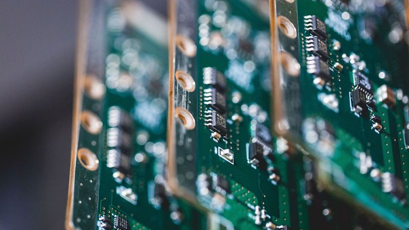
Batch of green printed circuit boards with components etched on it
No time now? Save for later.
We only use your email to send this link. Privacy Policy.
Introduction
Printed Circuit Board (PCB) materials form the foundation of electronic circuits, serving as the mechanical backbone and the electrical insulation for components and interconnections. A PCB substrate is a dielectric layer separating copper conductor layers and critically influencing how signals propagate. The material’s characteristics can alter signal attenuation, crosstalk, and electromagnetic interference, directly impacting signal integrity. For instance, a high-performance low-loss material will exhibit lower signal loss at high frequencies than a standard material.
Selecting the right PCB material is therefore a key decision in circuit design. The material must provide structural support, maintain electrical insulation, and meet the thermal and reliability requirements of the application. Essential properties such as dielectric constant, loss tangent, thermal stability, and moisture absorption determine whether a material is suitable for high-speed digital buses, radio-frequency (RF) circuits, high-temperature environments, or low-cost consumer gadgets. In short, understanding PCB materials is crucial for fabricating quality boards and ensuring that the circuit performs as intended under its operating conditions.
Types of PCB Materials
Modern PCBs can be made from various substrate materials. Each comes with its strengths, weaknesses, and ideal use cases. Here is a review of the most prevalent PCB material types.
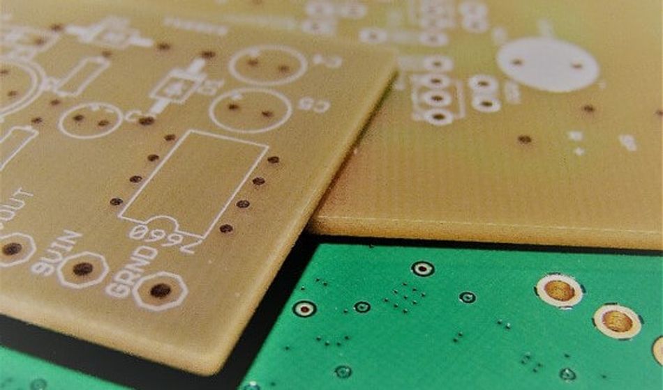
FR-4 (Glass Fiber Epoxy Laminate)
FR-4 is the most widely used PCB material. It is a composite of woven fiberglass cloth and epoxy resin binder, formulated to be flame-retardant (the "FR" stands for flame retardant). FR-4 has been the industry standard for decades due to its good balance of electrical, mechanical, and thermal properties at a relatively low cost. A typical FR-4 board has a dielectric constant (Dk) around 4.0 (ranging roughly 3.9 to 4.8 depending on resin content and frequency) and a dissipation factor (Df or loss tangent) around 0.02 (2%). This moderate Dk and low cost make FR-4 suitable for the majority of consumer and industrial electronics.
Key features of FR-4 include:
High mechanical strength
Minimal water absorption
Self-extinguishing flammability.
It retains its electrical insulating qualities even in humid conditions. Standard FR-4 can typically withstand temperatures up to about 130–140 °C (known as the glass transition temperature Tg, where the resin softens). High-Tg variants are available (Tg 170–180 °C) for lead-free soldering and better thermal durability. FR-4 is a cost-effective choice for multilayer PCBs and works well for frequencies from DC to low GHz.
Rogers High-Frequency Laminates
Rogers is a popular brand of high-performance PCB laminates, often used as a generic term for RF and microwave PCB materials. Rogers Corporation produces a range of substrates engineered for superior high-frequency performance compared to standard FR-4. These laminates typically have well-controlled dielectric constants and very low loss tangents. For example, Rogers RO4350B (a hydrocarbon ceramic laminate) has a Dk of about 3.48 (stable from 100 MHz to 10 GHz) and an extremely low Df of about 0.002 at 1 GHz.
Rogers laminates come in various formulations (PTFE-based, ceramic-filled, hydrocarbon, etc.) to offer a wide range of Dk values (≈2.5 up to 10+) and are designed for low dielectric loss and stable performance over frequency. They are well-suited for RF circuits, microwave communications, radar systems, and high-speed digital designs that demand tight impedance control. Rogers materials are more expensive than FR-4 and historically could be harder to process, but some series (like RO4000) are made compatible with standard FR-4 fabrication processes.
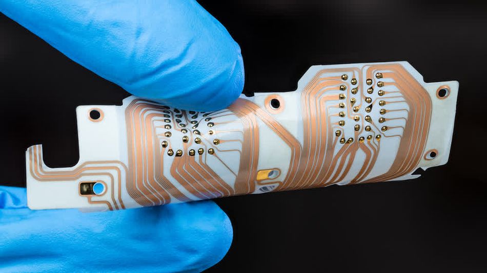
Polyimide (High-Temperature and Flexible PCB Material)
Polyimide is another common PCB material, known for its high thermal stability and use in flexible circuits. Polyimide films (such as DuPont’s Kapton) serve as the base for flexible PCBs (FPCs), while fiberglass-reinforced polyimide is used in rigid high-temperature PCBs (often in aerospace and military applications). A key advantage of polyimide resin systems is their very high glass transition temperatures around 250–260 °C, which allows polyimide boards to survive harsh thermal cycling and soldering processes, including the high temperatures of aerospace electronics.
Polyimide offers good electrical properties, comparable to FR-4, but absorbs significantly more moisture, requiring pre-assembly baking. Its resilience in extreme conditions makes it ideal for high-reliability and high-temperature applications.
Polyimide's flexibility and toughness are crucial for flexible circuits, enabling applications like smartphone antennas, foldable devices, and rigid-flex boards in various consumer, automotive, and medical devices.
Suggested Reading: Rigid Flex PCB: Revolutionizing Modern Electronics Design
PTFE (Teflon) and Other Low-Loss RF Materials
PTFE (Polytetrafluoroethylene), commonly known by the brand Teflon, is a polymer used in some of the lowest-loss PCB materials available. Pure PTFE has an extremely low dielectric constant (~2.1–2.3) and exceptionally low loss tangent. This makes it an ideal PCB material for high-frequency and microwave applications. Signals on PTFE-based boards suffer much less dielectric attenuation, which is critical for RF power amplifiers, microwave filters, and 5G antennas. PTFE also has a high chemical inertness and can withstand operating temperatures up to ~250 °C continuously (it’s a thermoplastic that melts around 327 °C).
Because PTFE is mechanically soft and non-rigid by itself, PCB laminates based on PTFE typically include fillers or reinforcing fibers to improve dimensional stability and strength. It’s worth noting that PTFE materials are more expensive and can be challenging to fabricate. Their softness can cause drilling and routing issues and the chemically inert, slick surface can make it hard for copper plating or solder masks to adhere without special surface treatments. Manufacturers often use special procedures (such as cold drilling techniques, plasma etching, or sodium etch on PTFE) and lamination with low-CTE prepregs to integrate PTFE layers in a board.
Ceramic Substrates
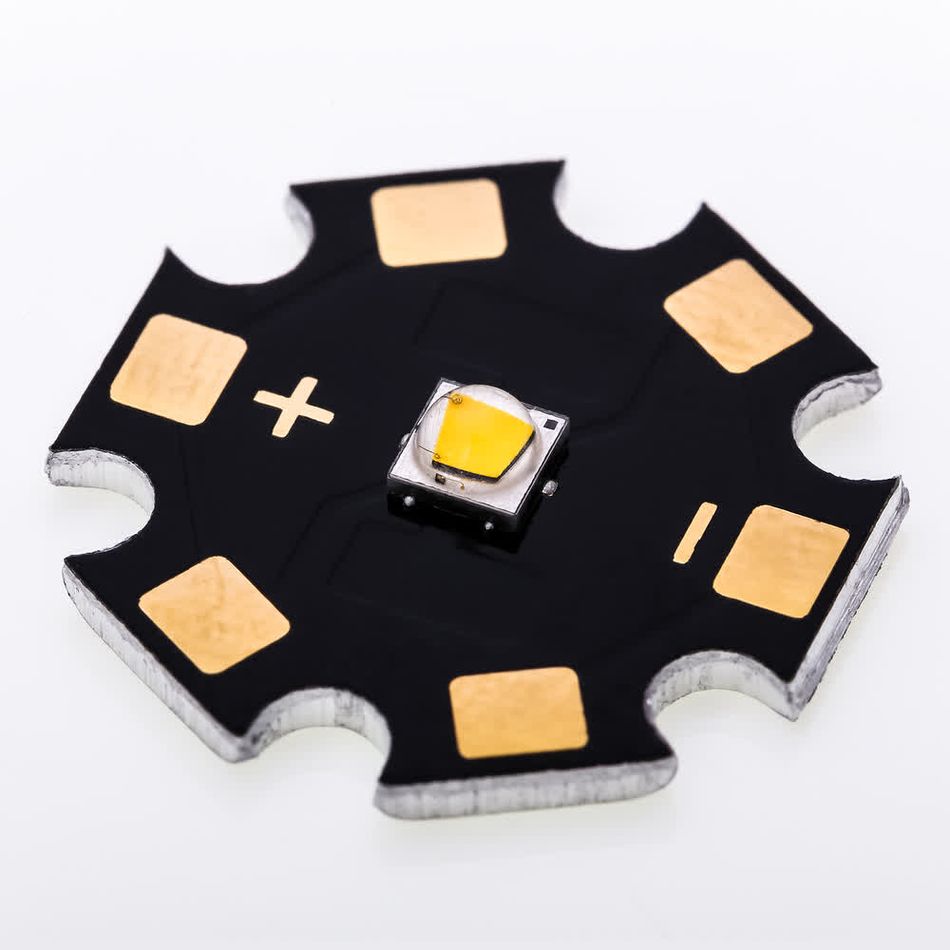
Ceramic PCBs utilize inorganic substrates like alumina or aluminum nitride, offering superior thermal performance and insulation compared to standard organic laminates. Alumina, with a thermal conductivity significantly higher than FR-4, and aluminum nitride, approaching metal conductivity, excel in heat dissipation. These rigid boards, featuring directly bonded copper or printed thick films, are ideal for high-power, high-temperature applications, benefiting from a low coefficient of thermal expansion that enhances reliability.
While ceramic PCBs are costly and limited in geometric complexity, they are invaluable for demanding environments. Their high thermal conductivity makes them perfect for LED lighting and RF power amplifiers, while their robustness suits aerospace, military, and extreme-condition electronics. Despite specialized manufacturing and higher costs, ceramic PCBs are the optimal choice for applications requiring exceptional thermal management, dielectric strength, and environmental resilience.
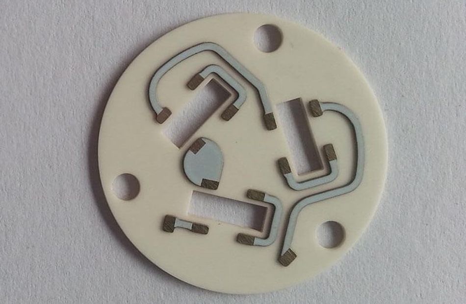 Fig 3: Ceramic-based substrate, Alumina (Al2O3), used in PCB; Link: andwinpcbOther High-Frequency and Specialty Materials
Beyond the main categories above, there are other niche and emerging PCB materials worth mentioning:
High-Speed Epoxy and Blend Laminates: PCB material suppliers offer improved versions of FR-4 for high-speed digital designs. These materials use modified epoxy or cyanate ester resins with lower Dk and Df. . Such laminates support multi-gigabit SERDES, high-definition video, and fast memory buses by reducing signal loss and dispersion. They often have higher Tg and slightly higher cost than FR-4, filling the gap between FR-4 and exotic RF materials.
Suggested Reading: RF PCB: Design, Materials, and Manufacturing Processes
- Metal-Core PCBs: In applications like LED lighting and motor drives, metal-core PCBs (MCPCBs) are used. These typically consist of a thin dielectric layer (often FR-4 or polyimide) laminated to a thick metal base (usually aluminum). The metal core dramatically lowers the thermal resistance, conducting heat away from components. While not a dielectric material by itself, metal-core board construction is a way to achieve better thermal management using conventional materials.
- CEM Materials: Composite Epoxy Materials (CEM-1, CEM-3, etc.) are low-cost laminates (often paper or fiber-based with epoxy or phenolic resin) used in some consumer electronics. They have inferior performance compared to FR-4 (higher Dk, more moisture absorption) but can be cheaper for simple boards like single-layer or low-end devices.
- Liquid Crystal Polymer (LCP): LCP is an advanced thermoplastic polymer recently used in high-frequency flexible circuits (e.g., smartphone antenna modules). LCP has a low Dk (~3) and very low loss, along with near-zero moisture absorption. It remains stable over a wide frequency range and temperature (up to ~200 °C). LCP has emerged as an ideal material for 5G antennas and high-frequency flexible modules because it outperforms polyimide in dielectric loss and moisture resistance.
The PCB material landscape continues to evolve, but the types above cover the majority of boards in today’s electronics. The table below summarizes some key properties of common PCB materials:
Material | Dielectric Constant (Dk) (@ Frequency) | Loss Tangent (Df) (@ Frequency) | Thermal Conductivity (W/m·K) | Tg (Glass Transition) (°C) | Typical Applications |
FR-4 (Glass Epoxy) | ~4.2 (1-10 MHz), ~4.0 (1 GHz) | ~0.02 | ~0.3-0.4 | 130-180 (varies by grade) | General-purpose PCBs, low-cost electronics |
High-Speed Epoxy | 3.5-4.0 (stable) | 0.005-0.015 | ~0.4-0.6 | 180-220 | High-speed digital (computers, networking) |
Polyimide (PI) | ~3.5-4.0 | ~0.01-0.02 | ~0.2-0.4 | 250-260 | Flexible PCBs, high-temperature applications |
PTFE (Teflon) | ~2.2-2.5 | 0.0005-0.005 | ~0.2 (pure), ~0.5 (filled) | N/A (no Tg) | RF/microwave circuits, high-frequency applications |
Rogers RO4350B | 3.48 (10 GHz) | 0.002 (10 GHz) | ~0.6 | N/A (no Tg) | RF/microwave, high-frequency digital |
Alumina Ceramic (Al₂O₃) | ~9.8 (1 MHz) | ~0.0001 | 24-30 | >300 (ceramic) | High-power LEDs, RF power modules, high-temperature electronics |
Aluminum Nitride (AlN) | ~8.8 (1 MHz) | ~0.0001 | 150-200 | >300 (ceramic) | High-performance power electronics, military RF, thermal management |
Material Properties and Selection Criteria
When choosing a PCB material, engineers must consider a range of material properties to ensure the board will meet electrical and environmental requirements. Key properties and selection criteria include:
Dielectric Constant
This is the relative permittivity of the material – essentially how much it can store electric field energy. Typical PCB dielectrics have Dk in the range of 2.5 to 4.5. A higher Dk slows down signal propagation (signals travel inversely to the square root of Dk) and increases the capacitance between traces.
High-Dk materials can thus increase propagation delay and even crosstalk
Low-Dk materials allow faster signal speeds.
For controlled impedance traces (like 50 Ω lines), the Dk influences the required trace geometry; consistent and stable Dk is critical for maintaining impedance targets. High-frequency designs benefit from materials whose Dk remains stable over a wide frequency range (low dispersion).
Dissipation Factor (Df or Loss Tangent)
This measures the dielectric losses in the material – how much signal power is lost as heat as an electromagnetic wave passes through. Lower Df is better for signal integrity, especially at high frequencies. Common FR-4 has Df ~0.02 (which is acceptable for lower frequency and digital signals), whereas specialized RF materials can have Df in the 0.001–0.005 range.
Dielectric loss isn’t very critical for slow signals or logic toggling at <100 MHz, but above 1 GHz (e.g. fast serial links or RF):
A high Df will cause noticeable attenuation of high-frequency components.
Alow-Df materials preserve signal amplitude and reduce heating.
Therefore, for high-frequency analog and multi-gigabit digital circuits, choose a low-loss material to maintain signal strength and integrity over distance.
Thermal Conductivity (k)
This is the ability of the substrate to conduct heat (measured in W/m·K). Most standard PCB laminates are poor thermal conductors – around 0.3–0.5 W/m·K, far lower than copper (~386 W/m·K). This means the copper planes and vias do most of the heat spreading in FR-4 boards.
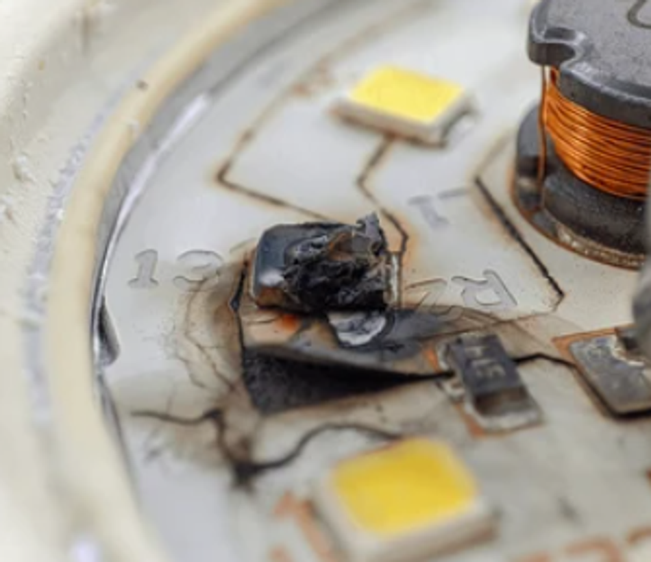
In high-power designs or LED boards, a low k can lead to hotspots unless thermal vias or metal backings are used. Materials like ceramic or metal-core laminates greatly improve k (20–200+ W/m·K), which helps keep components cool.
When selecting a PCB material for power electronics, thermal conductivity is a prime concern – high-k substrates allow heat to dissipate more efficiently. Even among FR-4 variants, there are “thermally conductive” epoxies (with filler) that modestly improve k to ~0.6–1.0 W/m·K.
Glass Transition Temperature (Tg)
Tg is the temperature at which the polymer base of the PCB transitions from a rigid, glassy state to a softer, rubbery state. It essentially marks the upper operating temperature for the material’s mechanical stability. Standard FR-4 has Tg around 130–140 °C, while high-Tg FR-4 and polyimide can go to 170 °C or 250 °C+ respectively. Exceeding Tg during operation can cause the board to warp, delaminate, or lose its properties.
For high-temperature applications, it is better to choose materials with a Tg comfortably above the maximum expected temperature. Also ensure the decomposition temperature (Td) is above solder reflow temperatures, so the material won’t chemically break down during assembly.
Suggested Reading: Glass Transition Temperature of Polymers
Coefficient of Thermal Expansion (CTE)
CTE measures how much the material expands per degree of temperature rise (ppm/°C). PCBs are composite structures and mismatched expansion between copper and substrate can strain vias and solder joints. FR-4 has a low CTE in the X-Y plane (~10–20 ppm/°C) due to glass fiber reinforcement, but a much higher CTE in the Z-axis (often 50–70 ppm/°C). When a board is heated, excessive expansion in Z can stress-plated through-holes (PTHs) and potentially cause cracks or via failures.
High-quality materials will have a low Z-axis CTE (some high-speed and RF laminates use ceramic fillers to achieve this ). For large multilayer boards or any design going through wide temperature swings, choose materials with controlled CTE to ensure reliability. Matching the CTE of the substrate to the components (and to any aluminum heat spreaders or cores) can be important in extreme environments.
Moisture Absorption
Water absorption by the PCB material can alter its electrical properties and affect reliability. Water has a very high dielectric constant (~80), so if the substrate absorbs moisture from humid air, the effective Dk rises and loss may increase, detuning high-frequency circuits. Additionally, moisture can vaporize during soldering, leading to delamination (“popcorning”).
FR-4 is formulated to be quite moisture-resistant (absorption often <0.1% by weight, whereas some polyimides and other materials might absorb 0.5% or more. If your product will operate in humid conditions or undergo wash cycles, moisture-resistant materials or proper PCB coatings should be considered. It’s also standard practice to bake PCBs before assembly if they’ve been exposed to humidity, especially for materials prone to moisture uptake.
Mechanical Properties
These include the flexural strength, hardness, and overall toughness of the PCB material. While not always a primary selection factor, they matter for boards that experience mechanical stress or flexing. FR-4, for instance, has excellent strength-to-weight ratio and dimensional stability, making it robust during drilling, depaneling, and in use.
Flexible laminates need high flex life (ability to bend repeatedly without cracking). Ceramics are extremely hard but also brittle – they offer virtually no flex. Depending on the application (e.g., a satellite PCB might see vibration, a car PCB might see shock), ensure the material can withstand the mechanical demands. Reinforced materials (with glass or aramid fibers) generally improve strength.
Cost and Availability
Last but certainly not least, cost is a practical selection criterion. Advanced materials can be an order of magnitude more expensive than FR-4 and may not be stocked by all PCB vendors. For example, a PTFE-based microwave laminate is much pricier than standard FR-4 and often has a higher manufacturing cost due to special processing requirements.
Impact on Signal Integrity and Performance
The choice of PCB material can have a profound impact on a circuit’s signal integrity (SI), especially in high-speed and high-frequency designs. Here are some key ways different materials affect electrical performance:
Impedance Control and Signal Speed
Materials with higher dielectric constants slow down signal propagation, potentially causing timing skew in digital designs. A consistent dielectric constant (Dk) is crucial for maintaining controlled impedance, which prevents signal reflections. Lower Dk materials support faster signal velocities and reduce impedance variability, making them preferable for high-speed signals.
Signal Loss and Attenuation
Dielectric loss, proportional to the material's loss tangent (Df), significantly impacts signal attenuation, especially at higher frequencies. Low-loss materials, like PTFE, preserve signal integrity over longer distances and at higher frequencies, crucial for maintaining the signal-to-noise ratio. High-loss materials like FR-4 introduce unacceptable losses at frequencies above a few GHz.
High-Frequency Behavior (Dispersion and Stability)
A stable dielectric constant across frequencies minimizes signal phase velocity and impedance variations, essential for wideband applications and fast rise-time signals. Fiber-weave effects in FR-4 can cause signal skew, prompting the use of homogenous dielectrics in high-frequency designs. Specialized materials are often needed to ensure uniform high-frequency propagation.
Crosstalk and EMI
Higher Dk materials can increase coupling between adjacent traces and layers, potentially increasing crosstalk. Lower Dk materials and thicker dielectrics reduce coupling capacitance, mitigating crosstalk. While high-loss materials might dampen high-frequency ringing, material selection should primarily focus on signal performance, with EMI controlled through design techniques.
Suggested Reading: EMI Shielding: Protecting Electronic Devices in a Noisy World
Power Integrity (Plane Capacitance)
High-Dk materials between power and ground planes increase planar capacitance, improving power delivery stability. This can act as a built-in decoupling capacitor, beneficial for high-speed boards. Hybrid stack-ups with high-Dk for power planes and low-Dk for signal layers are sometimes used to balance performance and loss considerations.
Manufacturing Considerations for PCB Materials
Different PCB materials not only have varied properties but may also require different manufacturing processes. When designing with a particular substrate, it’s important to consider how it will be fabricated and assembled:
Processing and Lamination
Standard FR-4 is the most fabrication-friendly material – PCB factories have well-established processes for drilling, plating, etching, and multilayer lamination with FR-4. High-Tg FR-4 and many polyimide materials can generally be processed similarly, just sometimes at slightly higher lamination temperatures.
However, pure PTFE-based boards require special handling: they often need pressing with PTFE prepregs, which flow differently than epoxy, and sometimes require nesting fixtures to maintain dimensional stability during lamination (because PTFE is soft and can creep).
Drilling and Machining
FR-4 and polyimide allow standard carbide drilling, while softer PTFE requires specialized techniques like sharp tools, backup materials, or CO₂ laser drilling due to its deformation risk and UV transparency. Ceramics necessitate diamond drills or pre-punching/laser cutting. Specialized via plating treatments, such as sodium or plasma etching for PTFE, may be required for proper copper adhesion, potentially increasing via costs and limiting aspect ratios.
Suggested Reading: PCB Drilling: Precision Techniques for Modern Electronics
Etching and Dimensional Stability
While copper etching is generally consistent, dimensional stability during manufacturing varies, impacting layer registration. Materials like FR-4 are stable, but polyimide or PTFE may shrink or stretch, requiring pre-baking. Hybrid stack-ups necessitate careful CTE matching to prevent misalignment.
Plated Through-Hole (PTH) Quality
Material selection affects PTH reliability, with ceramics requiring specialized metallization and PTFE needing considerations for Z-axis CTE during thermal cycling. Rogers materials offer reliable PTH performance due to low Z-axis expansion.
Solder Mask and Assembly
Smooth materials like PTFE may require surface roughening for solder mask adhesion, and high-Tg materials need compatible solder masks. Moisture-prone materials, like polyimide, require pre-baking to prevent delamination during assembly and reflow.
Multilayer and Hybrid Stack-ups
Hybrid PCBs, combining materials like Rogers and FR-4, offer cost savings but demand careful bonding and CTE matching to prevent delamination. Consult with the PCB fabricator early in the design process to ensure proper material compatibility and manufacturing feasibility.
Suggested Reading: PCB Layers: Everything You Need to Know
Cost Implications
Using exotic materials will increase the PCB cost due to both material price and extra processing steps. FR-4 is mass-produced and cheap; something like Rogers or ceramic can cost many times more per panel. Moreover, as noted, PTFE and other special materials often require extra labor and yield losses, further driving up cost.
This is acceptable for prototypes or high-value products (military RF, aerospace) but might be prohibitive for consumer products. Sometimes, designers will limit the use of expensive material to critical layers or even consider alternate approaches (like designing an RF module on a separate board with Rogers material, and the main board on FR-4, combining them in assembly). When quoting a board, expect a sizable cost increase for high-frequency laminates – and longer lead times if the shop has to order that material.
Suggested Reading: PCB Manufacturing Process: A Comprehensive Guide to Understanding and Mastering the Techniques
Industry Applications and Use Cases
PCB material choices often align with the requirements of specific industries. Here are some examples of industry applications and the PCB materials typically used:
Consumer Electronics
Cost sensitivity dictates widespread FR-4 use for digital and analog circuits, with polyimide flex materials enabling compact interconnects in devices like phones and wearables. Halogen-free FR-4 variants are increasingly adopted to meet environmental regulations. For specialized high-frequency components, materials beyond standard FR-4 might be selectively employed.
Telecommunications & Networking
High-frequency applications, such as RF base stations and routers, rely on materials like Rogers and PTFE for minimal signal loss; low-loss epoxy materials are used in high-speed digital backplanes to ensure signal integrity.
The need for precise dielectric constant control and low-loss tangent justifies the use of these specialized materials. Antenna arrays, power amplifiers, and low-noise amplifiers benefit from PTFE or ceramic-filled substrates.
Aerospace & Defense
High-reliability polyimide materials are favored for general avionics circuitry due to their ability to withstand harsh environments. For RF and microwave applications in radar and communication systems, PTFE-based laminates and ceramics are essential.
Performance and reliability are paramount, often outweighing cost considerations. Military and aerospace systems often require materials with low outgassing properties and stability across extreme temperature ranges.
Automotive Electronics
Durable high-Tg FR-4 and polyimide materials are used in engine and transmission controllers to withstand high temperatures and thermal cycling. Specialized RF materials, such as those based on hydrocarbon or PTFE, are crucial for ADAS radar and 5G connectivity modules.
The automotive environment demands materials with excellent humidity resistance and vibration durability, leading to a mix of material solutions.
Industrial & Medical
FR-4 remains common in industrial controls and medical devices, with high-Tg grades used for high-temperature applications. Metal-core PCBs or ceramic hybrids are employed in high-power industrial applications for efficient heat dissipation.
Medical devices with RF modules utilize low-loss materials, while miniaturized implants leverage flexible substrates like LCP and polyimide for biocompatibility and flexibility.
Emerging Trends in PCB Materials
As technology advances, PCB materials are evolving to meet new challenges. Here are some emerging trends and future directions in PCB material technology:
High-Speed Materials
5G and next-gen communication demand materials with low loss and stable Dk at millimeter-wave frequencies, driving the development of new laminates like LCP and MPI. Manufacturers are also improving materials for high-speed digital, targeting 56/112 Gbps SerDes with lower Df and better impedance control. The trend is to combine low loss, low Dk, and processability.
Flexible, Stretchable, and Wearable Substrates
Wearable electronics and IoT are driving demand for flexible, stretchable materials; polyimide is common, with new formulations improving endurance and stretchability. LCP is emerging as a high-performance flex material for RF, and printed electronics on PET/paper are developed for low-cost applications. Hybrid flexible materials, combining LCP and polyimide, are likely to increase.
Environmentally Friendly PCB Materials
Environmental regulations are pushing the industry towards halogen-free laminates and bio-based materials for sustainability. Lead-free assembly compatibility is now standard, and research focuses on recyclable or recoverable materials. Eliminating hazardous substances is a key requirement in material datasheets.
Suggested Reading: Lead vs. Lead-free Solder: Which is better for PCB manufacturing?
Integrated and Advanced Packaging Substrates
The line between PCBs and IC package substrates is blurring, with materials like BT resin and Ajinomoto film used in advanced packaging. HDI boards require thin, high-Tg dielectrics suitable for microvias. Emerging substrates include glass interposers and organic-glass composites for high-frequency, high I/O density applications.
3D Printing and Additive PCB Materials
3D printed electronics are emerging, allowing for custom substrate materials and additive circuit fabrication. Researchers are exploring printable dielectrics and composites for tailored material properties in specific regions. This field combines material science with additive manufacturing.
Suggested Reading: PETG Print Settings: Adjusting Temperature, Speed & Retraction to Improve Printing
Conclusion and Future Outlook
PCB material selection is critical, impacting performance, reliability, and manufacturing. While FR-4 remains versatile and cost-effective for general applications, specialized materials like Rogers and PTFE are essential for high-frequency designs, polyimide for flexibility, and ceramics for extreme thermal demands. Each material presents trade-offs in electrical, mechanical, and cost aspects, requiring careful evaluation of design requirements.
Future trends like 5G and IoT are driving advancements in PCB materials, offering lower dielectric constants, loss tangents, and higher thermal capabilities. Materials such as LCP and advanced epoxies are expanding design possibilities for multi-gigabit and millimeter-wave challenges. Innovations in flexible and environmentally friendly substrates are also emerging.
FAQ: PCB Material Selection
What is FR-4 and why is it commonly used in PCBs?
FR-4 is a grade designation for a fiberglass-reinforced epoxy laminate that is flame-retardant. It consists of woven glass fibers and epoxy resin, making it a strong electrical insulator with low water absorption. FR-4 is the most common PCB material because it is cost-effective and versatile – it has good mechanical strength and electrical properties suitable for a wide range of devices. In short, FR-4 offers a balance of performance and price that works for most consumer and industrial electronics.
2. When should I use Rogers or other high-frequency PCB materials instead of FR-4?
You should consider high-frequency laminates like Rogers when your design involves high-speed or RF signals that exceed the performance limits of FR-4. FR-4’s dielectric constant (~4.5) and higher loss tangent cause more signal loss at microwave frequencies. Rogers materials (or similar) have much lower loss and stable dielectric properties at GHz frequencies, so they are ideal for RF power amplifiers, microwave filters, antennas, or high-speed (>10 Gbps) digital routes. If signal integrity at high frequency is critical (for example, in 5G, radar, or low-noise analog circuits), switching to a Rogers material will greatly reduce dielectric losses and impedance variability.
3. Which PCB materials are used for flexible circuit boards?
Flexible PCBs typically use polyimide film as the substrate (often the material Kapton, by DuPont). Polyimide is chosen because it’s a plastic that can bend and twist while still being heat-resistant enough to endure soldering. The copper is bonded to the polyimide, and sometimes an adhesive layer is involved (though adhesive-less flex is common for better reliability). Polyimide flex material has a high Tg (~250 °C) and can handle repeated flexing. In many smartphones and laptops, you’ll find flex cables or antenna circuits made of polyimide – in fact, polyimide is the main substrate for mobile phone antennas and flex connectors. For even more demanding RF flexible circuits, Liquid Crystal Polymer (LCP) is emerging, but polyimide remains the standard for most flex PCB needs due to its proven performance and availability.
4. How does the dielectric constant of a PCB material affect my circuit design?
The dielectric constant (Dk) of the PCB material influences the speed at which signals propagate and the impedance of transmission lines on the board. A higher Dk means signals travel slower through the substrate and trace capacitance is higher. This affects timing and requires adjustments in trace geometry to hit impedance targets. For example, on a high-Dk material, you might need thinner or narrower traces to achieve 50 Ω than you would on a low-Dk material. Variation in Dk can also lead to inconsistent impedance. In practical terms, designers must account for Dk when doing impedance calculations and timing analysis. A stable, known Dk helps ensure that controlled-impedance traces (for USB, HDMI, DDR memory, etc.) work as intended.
5. Are there environmentally friendly PCB materials available?
Yes. The most notable are halogen-free PCB laminates, which avoid the use of brominated flame retardants found in standard FR-4. Halogen-free materials meet flammability requirements using alternative chemicals that do not contain chlorine or bromine, thereby reducing toxic emissions if the board burns. These materials are considered more environmentally friendly and are often required in “green” electronics initiatives.
6. Can I mix different PCB materials in one board (hybrid stack-up)?
A: Yes, it’s possible to have a hybrid multilayer PCB where different layers use different materials, though it requires careful manufacturing control. A common scenario is using a high-frequency material (like Rogers) on the layers carrying RF signals, and FR-4 on lower-speed layers or for structural layers. This can save cost because you’re only using the expensive material where needed. Many RF boards and some high-speed backplanes are built this way. The PCB fabricator will laminate the materials together into one stack-up.
References
1. PCB Substrates: Knowing PCB Dielectric Materials | Sierra Circuits
3. FR4 | Material Properties, Dielectric Constant, Circuit Boards
4. PCB Material Selection Guide | San Francisco Circuits
5. PTFE Vs. Non-PTFE RF PCB Laminates | Sierra Circuits
in this article
1. Introduction2. Types of PCB Materials3. Fig 3: Ceramic-based substrate, Alumina (Al2O3), used in PCB; Link: andwinpcbOther High-Frequency and Specialty Materials4. Material Properties and Selection Criteria5. Impact on Signal Integrity and Performance6. Manufacturing Considerations for PCB Materials7. Industry Applications and Use Cases8. Emerging Trends in PCB Materials9. Conclusion and Future Outlook10. FAQ: PCB Material Selection11. ReferencesNo time now? Save for later.
We only use your email to send this link. Privacy Policy.