Step-Up vs Step-Down Transformer: Engineering Guide to Voltage Transformation
This technical guide provides a comparative analysis of step-up and step-down transformers covering turns ratio, grid voltage levels, design parameters, autotransformers, buck-boost configurations, efficiency standards and selection criteria.

09 Apr, 2026. 12 minutes read
Step-Up vs Step-Down Transformer; Design, Voltage, Current, and Power Formulas
Key Takeaways
Turns Ratio Determines Function: The step-up transformer has more turns on the secondary winding than the primary winding, increasing output voltage. A step-down transformer reverses this relationship, with fewer turns on the secondary side, producing a lower voltage.
Grid Integration Requires Multiple Stages: Generators produce electricity at 11 kV to 28 kV. Step-up transformers elevate voltage to transmission levels (132 kV to 400 kV) to minimize current and resistive losses. Substation step-down transformers then reduce voltages in stages (e.g., 33 kV/11 kV/400 V) for industrial and residential loads.
Design Differences Influence Materials and Current: In a step-up transformer the primary winding carries high current, so it uses thicker conductors, while the secondary winding uses thinner wire; the reverse is true for step-down designs. The power rating (kVA) is the same on both sides because transformers ideally exchange energy without loss.
Efficiency and Regulation are Governed by Standards: The IEC 60076 series defines general requirements, temperature rise, dielectric tests and loading guides for all transformer classes. The U.S. DOE 2016 rules require high distribution-transformer efficiencies and updated 2029 standards mandate 10 to 30% loss reductions.
Specialized Transformer Types Extend Capability: The auto-transformers share a single winding and offer compact voltage adjustment at lower cost but lack isolation. The buck-boost transformers provide plus or minus 5 to 20% voltage correction for HVAC and lighting systems. The pad-mounted transformers are tamper-resistant distribution units up to approximately 10 MVA for underground networks.
Selection is Application Dependent: Engineers must consider kVA rating, voltage class, impedance, cooling method, insulation class, load characteristics and regulatory compliance. The renewable power plants often use two-stage step-up transformers: from 600 to 1500 V (solar) or 400 to 690 V (wind) to 33 to 110 kV.
Introduction
Transformers enable the modern power grid by converting voltage levels at every stage of electricity delivery. Without step-up transformers at generation plants, transmission losses would make long-distance power delivery impractical. Without step-down transformers at substations and distribution points, voltages would be too high for safe use in buildings and equipment.
Understanding the distinction between step-up vs step-down transformers is essential for power system engineers, electronics designers and technicians. Both transformer types operate on the same principle of electromagnetic induction, but their winding configurations, insulation requirements and applications differ significantly.
This article provides a detailed analysis of step-up vs step-down transformers covering turns ratio, grid voltage levels, design parameters, autotransformers, buck-boost configurations, efficiency standards and selection criteria.
How Transformers Work: Electromagnetic Induction
The transformer is a passive electromagnetic device used to transfer electrical energy between circuits through the principle of electromagnetic induction. It typically consists of two or more windings: namely the primary winding and secondary winding, wound around a common magnetic core made of laminated ferromagnetic material to reduce energy loss due to eddy currents.
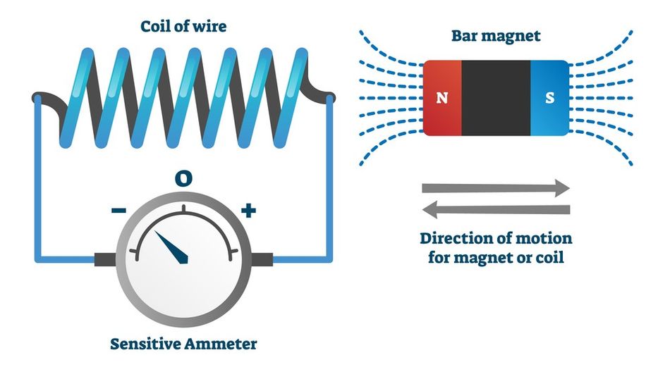
Once alternating current flows through the primary winding, it creates a time-varying magnetic field in the core. This changing field induces a voltage in the secondary winding according to Faraday's Law of electromagnetic induction. [1]
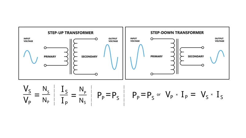
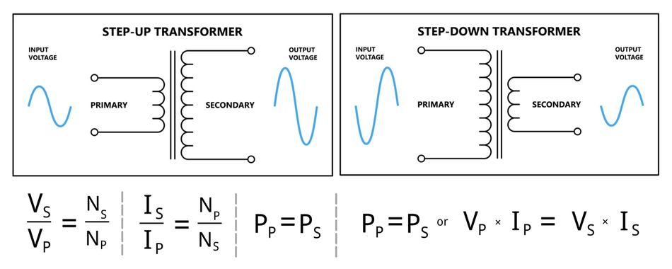
The fundamental relationship is:
Vs / Vp = Ns / Np
where Vp and Vs are the primary voltage and secondary voltage, and Np and Ns are the number of turns in the primary winding and secondary winding respectively.
From a power perspective, transformers ideally conserve power:
Vp x Ip = Vs x Is
This means that when a transformer is used to increase voltage, the current decreases to maintain power balance, resulting in lower current and reduced power loss over long-distance transmission through power lines and transmission lines. Conversely, when voltage is reduced for power distribution, current increases to supply electrical devices and industrial equipment safely at appropriate voltage levels.
This explains why transformers are critical components in power grids, enabling efficient power transmission from power plants to substations and ultimately delivering usable low voltage power for end users.
Recommended Reading: Electrical Transformers: Engineering Fundamentals, Design Parameters, and Emerging Trends
Step-Up Transformer: Principles and Applications
How a Step-Up Transformer Works?
The step-up transformer is designed to increase voltage from the primary winding to the secondary winding. In this configuration, the number of turns on the secondary coil (Ns) is greater than that of the primary coil (Np), resulting in a higher voltage at the secondary side and a corresponding reduction in current. This principle is fundamental in electrical engineering, especially for optimizing power transmission.
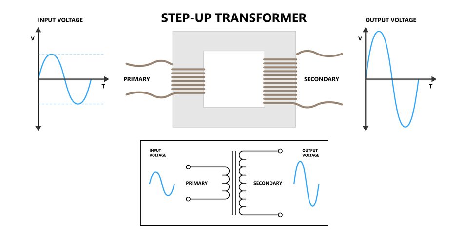
The relationship follows: increasing output voltage leads to lower current, which significantly reduces power loss and energy loss across transmission lines during long-distance transmission.
Physical Design
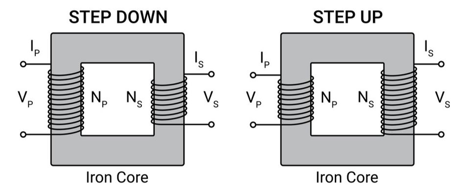
Primary Winding: Contains fewer turns and uses thicker conductors to handle high current at lower primary voltage.
Secondary Winding: Comprises more turns with thinner conductors, forming high voltage windings that deliver higher voltage at reduced current.
Insulation System: Designed to withstand high voltage, with enhanced insulation class and BIL ratings to ensure safe operation under elevated voltage levels.
Applications
Power Plants: Electrical generators produce electrical power at relatively medium voltage levels (typically 11 kV to 25 kV). A step-up transformer raises this to high voltage (115 kV to 765 kV) for efficient power transmission across power grids. [2]
Long-Distance Transmission: By increasing voltage and reducing current, step-up transformers minimize power loss (I²R losses) in power lines, making energy transfer over long distances highly efficient.
Renewable Energy Systems: Wind turbines and solar systems generate low voltage or medium voltage output. Step-up transformers elevate these to grid-compatible voltage levels for integration into power distribution networks.
Industrial Applications: High-voltage requirements in equipment such as X-ray systems, particle accelerators, and specialized industrial equipment rely on step-up transformers to generate the necessary electrical conditions.
This highlights the importance of step-up transformers in enabling efficient energy flow from generation sources to large-scale infrastructure and advanced electrical devices.
Step-Down Transformer: Principles and Applications
How a Step-Down Transformer Works?
The step-down transformer is designed to decrease voltage from the primary winding to the secondary winding. In this configuration, the number of turns on the secondary coil (Ns) is lower than that of the primary (Np), resulting in a lower voltage at the secondary side and a corresponding increase in current. This process, often referred to as voltage step-down, ensures that high transmission voltages are converted into safe and usable voltage levels for downstream systems.
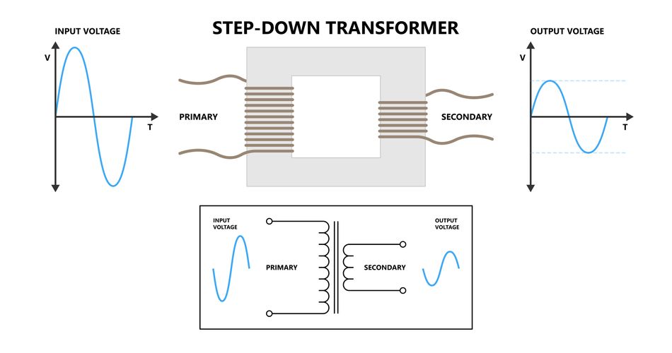
In this type of transformer, the reduction in secondary voltage leads to high current output. This makes them essential for power distribution where electrical devices require stable and controlled power supply conditions.
Physical Design
Primary Winding: Consists of more turns with thinner conductors, handling high voltage and relatively lower current at the input side.
Secondary Winding: Designed with fewer turns and thicker conductors to carry high current at lower voltage efficiently.
Thermal Management: Due to increased current on the secondary side, effective cooling systems and appropriate conductor sizing are critical to minimize power loss and ensure operational reliability.
Applications
Distribution Substations: High primary voltage from power transmission networks (132 kV to 400 kV) is reduced to medium voltage levels (4 kV to 35 kV) at each substation, enabling localized power distribution.
Residential and Commercial Supply: Final-stage step-down transformers convert electricity to low voltage suitable for homes and offices, powering everyday electrical devices safely.
Industrial Applications: Machinery, drives, and heavy industrial equipment rely on precise secondary voltage levels delivered by step-down transformers for efficient operation.
Power Supply Units: Many electronic systems incorporate voltage transformers as part of their design, where step-down transformers reduce input voltage before rectification and regulation stages.
Data Centers: Large-capacity units (typically 750–3000 kVA) are used to step down medium voltage supply to standardized levels (e.g., 480 V) for critical infrastructure in data centers.
This demonstrates the importance of step-down transformers in safely converting high voltage electrical energy into usable forms, ensuring reliable operation across residential, commercial, and industrial sectors.
Recommended Reading: How to Make a Transformer: Engineering Principles and Best Practices
Head-to-Head Comparison
Below is the detailed, head to head comparison of step-up vs step-down transformers:
Parameter | Step-Up Transformer | Step-Down Transformer |
Turns Ratio | Ns > Np (ratio greater than 1) | Ns < Np (ratio less than 1) |
Voltage Transformation | Increases Voltage from Primary to Secondary | Decreases Voltage from Primary to Secondary |
Current Behavior | Secondary Current is Lower than Primary | Secondary Current is Higher than Primary |
Primary Winding | Fewer Turns, Thicker Conductor | More Turns, Thinner Conductor |
Secondary Winding | More Turns, Thinner Conductor | Fewer Turns, Thicker Conductor |
Insulation Emphasis | High Voltage Insulation on Secondary Side | High Current Thermal Management on Secondary |
Grid Location | Power Plants, Generation Substations | Distribution Substations, Consumer Endpoints |
Typical Voltage Range | 11 kV to 765 kV (Output) | 400 V to 33 kV (Output) |
Cost Drivers | High Voltage Insulation, BIL Requirements | Copper Volume, Cooling Systems |
Key Standards | IEC 60076, IEEE C57 | IEC 60076, DOE 2016/2029 Efficiency |
Power Grid Voltage Levels
The modern power grid operates through multiple stages of voltage transformation to ensure efficient delivery of electrical energy from power plants to end users.
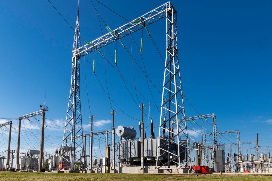
Each stage uses a specific transformer type to adjust voltage levels, balancing efficiency, safety, and performance.
1. Generation Stage: Electricity is produced at medium voltage levels, typically between 11 kV and 28 kV. [3] A step-up transformer, often referred to as a generator step-up (GSU) unit, is used to increase voltage to high voltage levels. This is essential for efficient power transmission over long distances, as higher voltage reduces current and minimizes power loss in transmission lines.
2. Transmission Stage: During the transmission stage, voltages range from 132 kV to 765 kV. Maintaining high voltage and lower current ensures reduced I²R losses across extensive power lines, making long-distance energy transfer economically viable.
3. Sub-Transmission Level: Here, voltages are reduced from 33 kV to 132 kV using step-down transformers located in each substation. This prepares electricity for regional power distribution.
4. Primary Distribution: In primary distribution, voltage is further reduced to 4 kV–35 kV (medium voltage), supplying industrial equipment, commercial facilities, and local substations.
5. Secondary Distribution: Finally, secondary distribution delivers low voltage power; typically 120/240 V or 230/400 V, through step-down transformer units such as pad-mounted transformers, ensuring safe operation of everyday electrical devices and power supply systems.
Recommended Reading: Energy Storage Solutions: Saving Power for the Future
Autotransformers and Buck-Boost Transformers
Autotransformers
An autotransformer uses a single continuous winding with taps to provide both step-up and step-down capability.
Unlike conventional power transformers with separate primary winding and secondary winding, a portion of the winding is shared between input and output, directly transferring electrical energy through conductive coupling as well as electromagnetic induction.
Advantages: The auto-transformers offer higher efficiency, reduced energy loss, compact size, and lower cost compared to equivalent dual-winding designs. Their lower leakage reactance improves voltage regulation, making them suitable for stabilizing voltage levels in power grids.
Disadvantages: The absence of electrical isolation between the primary voltage and secondary voltage introduces safety concerns. The faults or surges on the primary side can propagate directly to the secondary side, limiting their use in sensitive electrical devices and safety-critical industrial applications.
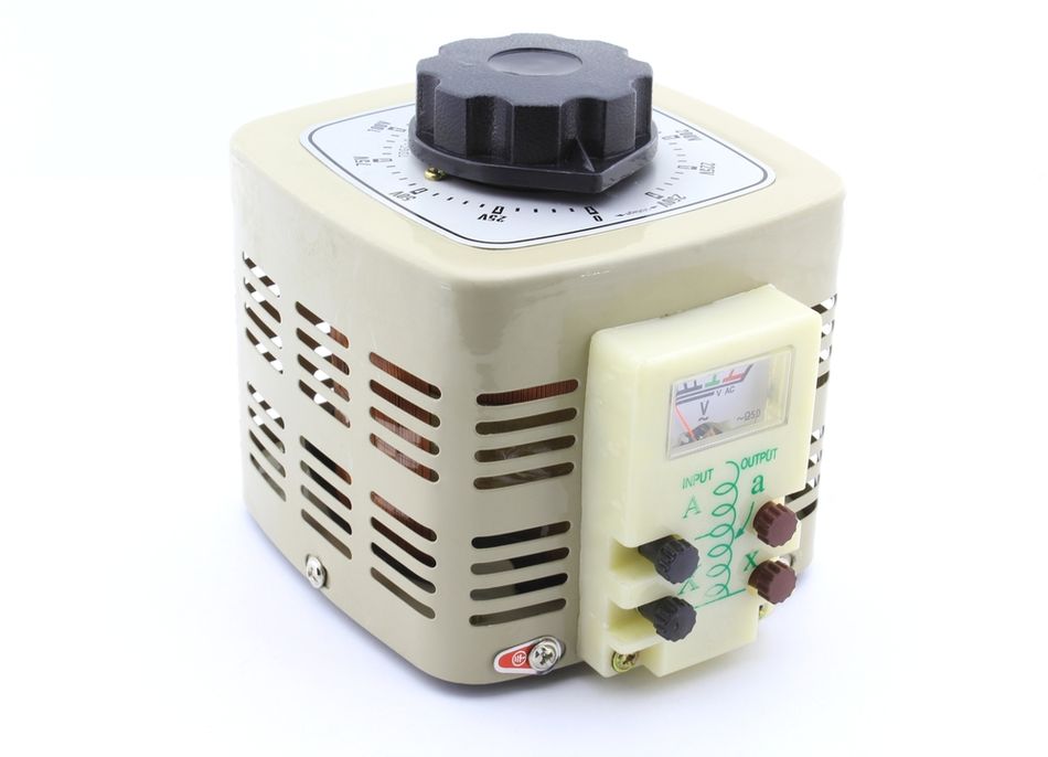
Applications: Commonly used in substation voltage regulation (e.g., 132 kV/110 kV), motor starting systems to limit high current, and variable AC supplies such as variacs in laboratories.
Buck-Boost Transformers
Buck-boost transformers are compact single-phase units typically configured as autotransformers to fine-tune output voltage by small margins (typically 5–20%). They are widely used to correct input voltage fluctuations in power supply systems without requiring full-scale voltage transformers.
These transformers are ideal for maintaining stable lower voltage or slightly higher voltage outputs in lighting systems, HVAC units, and industrial equipment. Although they do not provide isolation, they are a cost-effective solution for minor adjustments in power distribution networks.
Typically limited to loads below approximately 150 kVA, their configuration depends on system requirements: single unit for single-phase, or multiple units for three-phase systems (open-delta or closed-delta). [4]
Recommended Reading: Buck Converters: A Comprehensive Guide for Hardware Design Engineers
Design and Selection Criteria
Selecting the appropriate transformer type requires careful evaluation of electrical, thermal, and environmental parameters to ensure reliable performance across power distribution and industrial applications. Below are the key parameters:
kVA Rating: defines the maximum apparent power a transformer can handle and must be calculated based on load demand, future expansion, and expected electrical power consumption. Choosing the correct rating prevents overheating and extends service life.
Voltage Class: must align with both primary voltage and secondary voltage requirements, ensuring compatibility with system voltage levels across power grids and power transmission networks. The tap changers may be included to adjust output voltage under varying load conditions.
Impedance: typically between 4% and 12%, plays a critical role in limiting fault current and maintaining voltage regulation. Proper impedance selection directly impacts system stability and power loss.
Cooling Method: is essential for thermal management. Smaller units use ONAN (Oil Natural Air Natural), while larger power transformers rely on ONAF or OFAF/ODAF systems to dissipate heat generated by high current and electrical energy transfer.
Insulation Class: determines allowable operating temperature, with higher classes supporting more demanding high voltage environments. Efficiency is equally important, as modern regulations aim to reduce energy loss and improve overall system performance.
The load characteristics, whether resistive, inductive, or harmonic-rich, affect transformer heating and design. Additionally, environmental conditions such as altitude, ambient temperature, and installation location must be considered to ensure durability and compliance with standards like IEC 60076 and IEEE C57.
Application Selection Table
Application | Rating and Voltage | Key Considerations |
Utility Step-Up (GSU) | 100 to 800 MVA, 13.8 kV/230 kV | High Impedance (8 to 12%); ONAN/ONAF Cooling; Tertiary Winding for Harmonic Control |
Solar Farm Collection | 1 to 5 MVA, 1000 V/33 kV | Pad-Mounted Design; Ester Oil or Dry Type; Wide Tap Range |
Pad-Mounted Distribution | 50 to 2500 kVA, 33 kV/400 V | Tamper-Proof Enclosure; 4 to 6% Impedance |
Industrial Machine Tool | 50 to 500 kVA, 480 V/240 V | Step-Down Isolation; K-Factor Rating for Harmonic Loads |
Data Center | 750 to 3000 kVA, 13.2 kV/480 V | High Efficiency (greater than 98%); Dual Secondary for Redundancy; Cast-Coil Dry Type |
Energy Losses and Efficiency
Transformer efficiency is a critical factor in electrical engineering, directly impacting power loss, operational cost, and long-term reliability in power grids and industrial applications.
Regardless of the transformer type, losses occur due to physical and electromagnetic phenomena during energy conversion.
Loss Mechanisms
Core Losses (No-Load): Hysteresis and eddy current losses in the magnetic core. Reduced by using high-quality grain-oriented steel, thinner laminations or amorphous metal cores.
Copper Losses (Load-Dependent): I²R heating in the windings. Increases with load current. Proper conductor sizing and cooling minimize these losses.
Stray and Dielectric Losses: Leakage flux induces eddy currents in structural components; insulation resistance creates dielectric losses.
Efficiency Standards
DOE 2016: Requires minimum efficiencies for liquid-filled and dry-type distribution transformers (e.g., 99.23% for 333 kVA liquid-filled).
DOE 2029: Mandates 10 to 30% further loss reductions with efficiencies up to 99.64% for large units.
IEC 60076: Defines testing procedures, temperature rise limits and loading guides for all transformer classes.
Optimizing transformer efficiency is essential for reducing operational costs, minimizing environmental impact, and ensuring reliable delivery of electrical energy across modern power systems.
Recommended Reading: Innovative Transformer Solution Addresses Traditional Challenges
Future Trends
The evolution of transformer technology is being driven by the need for higher efficiency, digital integration, and sustainability across modern power grids and industrial applications.
Smart Transformers and Digital Monitoring: IEC 60076-19 introduces testing for digital monitoring systems, enabling online dissolved gas analysis, temperature and partial discharge sensing.
Renewable Specific Designs: IEC 60076-16 addresses transformers for wind and solar applications, focusing on fluctuating loads and harmonic spectra.
Solid State Transformers (SSTs): Under draft IEC 60076-20, next-generation transformers integrate power electronics for voltage regulation and DC-compatible operation.
Ecological Design: Updates introduce criteria for carbon footprint tracking, biodegradable insulation fluids and recyclable materials.
AI-Driven Design and Maintenance: The digital twins optimize transformer sizing, thermal design and predict maintenance schedules based on real-time data.
Conclusion
Step-up and step-down transformers are fundamental to delivering electrical power efficiently and safely. By manipulating the turns ratio, engineers tailor voltage and current to suit generation, transmission and consumption. Step-up transformers raise generator voltages to high levels to minimize current and losses, while step-down transformers reduce transmission voltages to usable levels for industry and households. Differences in winding design, insulation and applications result from their opposing roles. Specialized types such as autotransformers, buck-boost transformers and pad-mounted units expand the engineer's toolkit, while international standards like IEC 60076 and DOE efficiency rules ensure safety, interoperability and energy efficiency. As the energy landscape embraces renewable sources, electrification and digitalization, transformers will continue to evolve with smart monitoring, eco-friendly materials and solid-state architectures.
Frequently Asked Questions (FAQs)
Q1. How does a transformer differ from an inductor?
A. Both use coils and magnetic cores, but a transformer has at least two windings that transfer energy via mutual induction, whereas an inductor has one winding and stores energy in its magnetic field. A transformer changes voltage and current levels; an inductor resists changes in current.
Q2. Why can't transformers work with direct current (DC)?
A. Transformers rely on a changing magnetic field to induce voltage in the secondary winding. DC produces a constant magnetic field and does not induce a voltage; it will cause the primary winding to overheat and saturate the core.
Q3. What determines transformer efficiency?
A. Efficiency depends on core losses, copper losses, stray losses and dielectric losses. High-quality core materials, adequate conductor sizing, proper cooling and operation near rated load maximize efficiency. DOE 2016/2029 and IEC standards specify minimum efficiencies based on kVA rating.
Q4. How do autotransformers compare with isolation transformers?
A. Autotransformers share a single winding and are smaller and more efficient for small voltage changes. However, they do not provide electrical isolation. Isolation transformers have separate windings and provide galvanic isolation, making them safer for sensitive equipment.
Q5. Why are pad-mounted transformers preferred in urban areas?
A. Pad-mounted transformers are enclosed in lockable cabinets installed at ground level. They eliminate fenced substations or pole-mounted equipment and can supply up to 10,000 kVA. Their tamper-resistant design enhances safety and aesthetics.
Q6. What is the difference between buck-boost and tap-changing transformers?
A. Buck-boost transformers provide small voltage adjustments (plus or minus 5 to 20%) by wiring two low-voltage windings as an autotransformer. Tap-changing transformers adjust the turns ratio in discrete steps (often plus or minus 2.5% or 5%) without interruption, enabling regulation of transmission voltage under varying load.
Q7. How do renewable energy transformers differ from conventional ones?
A. Renewable transformers must handle variable power output, high harmonic content from inverter switching and potential DC bias. IEC 60076-16 specifies increased thermal capacity, low-loss core steel and high BIL. They often use environmentally friendly ester fluids and include smart sensors.
References
[1] SimScale. What is Electromagnetic Induction? (Faraday's Law) [Cited 2026 April 6]; Available at: Link
[2] Wikipedia. Electric Power Transmission (Faraday's Law) [Cited 2026 April 6]; Available at: Link
[3] ScienceDirect. Book: Practical Power System and Protective Relays Commissioning; Chapter 1: Power System Elements [Cited 2026 April 6]; Available at: Link
[4] EEPower. Winding Connections and Applications of Buck-Boost Transformers [Cited 2026 April 6]; Available at: Link
in this article
1. Key Takeaways2. Introduction3. How Transformers Work: Electromagnetic Induction4. Step-Up Transformer: Principles and Applications5. Step-Down Transformer: Principles and Applications6. Head-to-Head Comparison7. Power Grid Voltage Levels8. Autotransformers and Buck-Boost Transformers9. Design and Selection Criteria10. Energy Losses and Efficiency11. Future Trends12. Conclusion13. Frequently Asked Questions (FAQs)14. References