How to Make a Transformer: Engineering Principles and Best Practices
Understanding the basics of electrical transformer design, types, strategies, trade-offs, and effective implementation practices.

09 Jun, 2025. 18 minutes read
Key Takeaways:
Transformers enable efficient AC voltage conversion via electromagnetic induction, requiring careful design of the core, windings, and insulation.
The core architecture (e.g., shell vs. core type) and material (silicon steel vs. ferrite) must match the application's frequency and power level for optimal performance.
Performance metrics such as turn ratio, efficiency, regulation, and temperature rise are critical to transformer design; large units can achieve efficiencies of nearly 99%.
Safe integration involves correct phasing, proper protection (fuses, breakers), and compliance with safety standards (IEC 61558, IEEE C57 series).
Modern alternatives (high-frequency transformers in SMPS, solid-state transformers) offer weight and functionality advantages but introduce complexity and require advanced design techniques.
Introduction
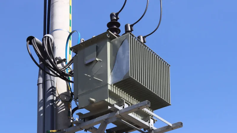
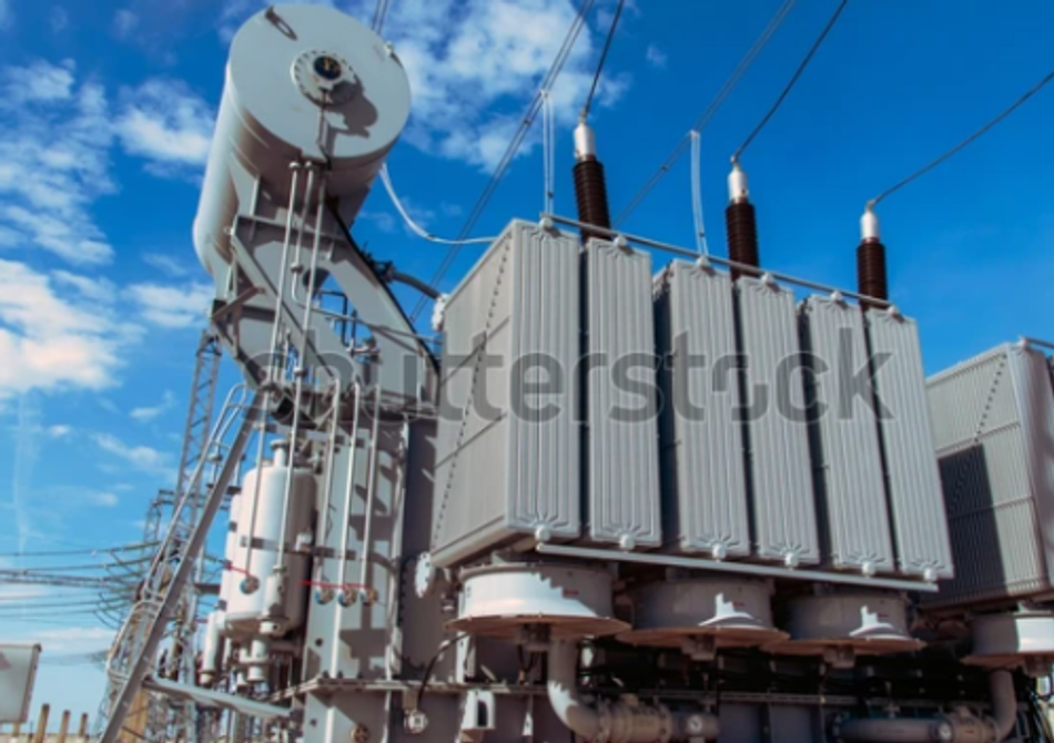
The design of a transformer is a meticulous process involving precise engineering that enables it to control voltage and current transformation. Ranging from low- to high-voltage applications, transformers have been a critical part of the power generation and distribution industry for decades.
This article discusses the key principles, design techniques, architectures, performance analysis, and implementation of electrical power transformers. It should enable engineers and designers to pick the most efficient design techniques for reliable operations in both commercial and residential sectors.
Foundational Principles & Terminology
Transformers are electromagnetic devices that transfer AC electrical energy between two or more circuits through a shared magnetic field. They consist of a primary winding (input coil) and secondary winding (output coil) wrapped around a common magnetic core.
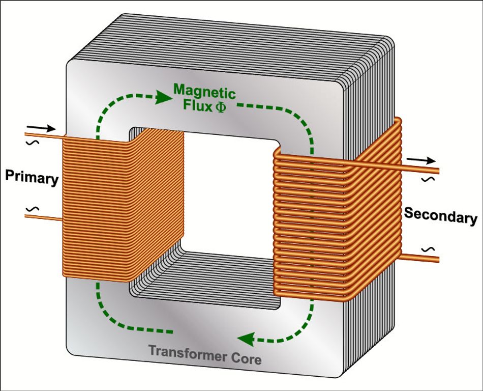
When an alternating current flows in the primary, it creates a time-varying magnetic flux (Φ) in the core, which induces a voltage in the secondary by Faraday’s law of induction. This principle of mutual induction allows transformers to step voltage up or down without a direct electrical connection between windings (providing galvanic isolation).
Key Terms and Concepts in Transformer Design
The following are the key terms in a transformer design:
Primary Side - The side that receives power.
Secondary Side - Delivers power
Turns Ratio (Np/Ns) - Ratio of the number of turns of wire on the primary vs. secondary. It governs the voltage ratio according to Vp/Vs = Np/Ns. For example, a 2:1 turns ratio means the secondary voltage is half the primary voltage (for an ideal transformer). Likewise, the current ratio in an ideal transformer is IP/IS = NS/NP to conserve power.
Ideal Transformer - A constant-power device where Pout = Pin (ignoring losses). In practical terms, if the voltage is stepped down, the current is stepped up, and vice versa.
Magnetic Flux - Transformers only work with a changing magnetic flux, i.e., AC or pulsating waveforms. A steady DC cannot induce a voltage in the secondary, and will drive the core into saturation and cause overheating.
Core - Made of ferromagnetic material to channel the magnetic flux efficiently. Using a magnetic core greatly increases coupling between windings compared to an air-core, but designers must avoid core saturation by not exceeding the material’s flux density limits.
~1.3–1.6 T for silicon steel
~0.3–0.35 T for ferrite
Induced Voltage - The induced voltage in a winding is given by
E = N·dΦ/dt;
For a sinusoidal excitation, this leads to the design equation N = E / (4.44 f Bmax Acore), where:
Bmax is the chosen peak flux density
Acore is the core cross-sectional area.
Basic Types of Transformers
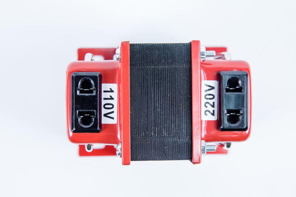
Depending on the turns ratio and connection, transformers are classified as step-down, step-up, or isolation transformers:
Type | Turns Ratio (NP:NS) | Voltage Relation | Current Relation | Typical Application |
Step-Down | Greater than 1 (e.g. 2:1) | VS < VP (reduced) | IS > IP (increased) | AC adapters, low-voltage power supplies |
Step-Up | Less than 1 (e.g. 1:5) | VS > VP (elevated) | IS < IP (decreased) | CRT/flyback, ignition coils, amplifiers |
Isolation (1:1) | ~1:1 | VS ≈ VP (same) | IS ≈ IP | Safety isolation, impedance matching |
The good thing about transformers is their usability in both directions. The same transformer can act as a step-up and step-down transformer, based on where it receives the input supply. For instance, a 2:1 turn ratio transformer acts as a step-down transformer. But if we flip the transformer, the roles of primary and secondary sides are also switched. Hence. It will act as a step-up transformer, doubling the input voltage due to its turn ratio.
Transformer Architecture & Variants
Transformers’ operating principle is universal, but the architecture varies according to its structure and applications.
Structural Variants
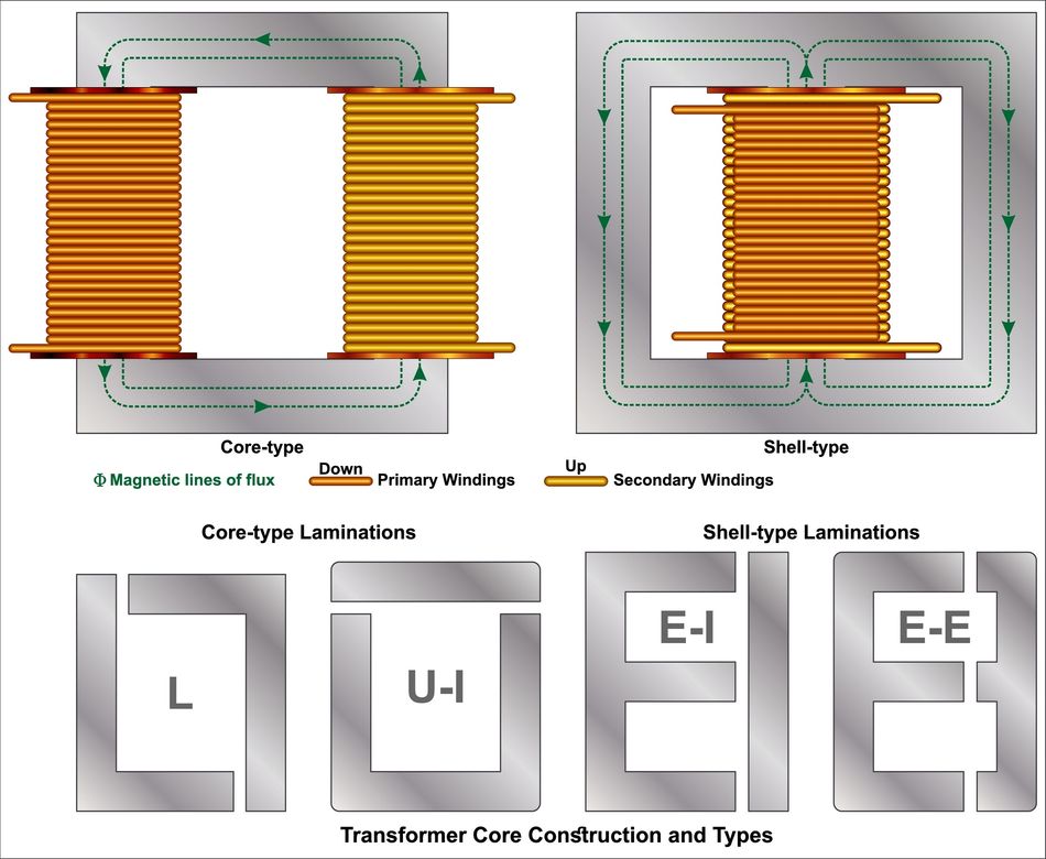
The main structural distinction is how the core and coils are arranged i.e., core-type vs. shell-type.
In core-type (closed-core) transformers, the windings encircle the core; typically, half the primary and half the secondary are wound on each leg of a two-leg core.
In shell-type, the core surrounds the windings – primary and secondary coils are placed on a central limb and enclosed by outer core limbs (forming a shell around the coils).
Shell designs confine more flux within the core and reduce leakage inductance, but they are more complex core assemblies.
A toroidal transformer is another common type where windings are uniformly distributed around a ring-shaped core. They can achieve very tight magnetic coupling and low stray fields, and are often smaller and more efficient than E-I core equivalents for the same rating.
Application Variants
Transformers are also categorized by intended application and frequency:
High-Frequency Transformers: Found in switch-mode power supplies, inverters, or RF circuits, operating from kHz up to MHz. They use ferrite or other soft ferrite-like materials and often have much smaller core sizes. High frequency reduces the required turns for a given voltage (since E∼4.44fNAΦ) and allows significantly smaller transformers for the same power, but these must handle higher AC flux and often non-sinusoidal waveforms. Special winding techniques (like litz wire to reduce skin effect, or planar PCB windings for very high frequency) are used.
Audio Transformers: Used for impedance matching and coupling in audio-frequency circuits (20 Hz–20 kHz). Examples include output transformers in vacuum tube amplifiers (matching tubes’ high plate impedance (kΩ) to low speaker impedance (Ω)) and line isolation transformers. Audio transformers must have a wide, flat frequency response and low distortion. They often use high-permeability cores like special silicon steel, and are designed to avoid saturation at low frequencies (since music signals can have DC bias or large low-frequency components). Design tricks include air gaps for single-ended tube output transformers to handle DC bias current, and interleaved windings to improve high-frequency response by reducing leakage inductance.
RF/Microwave Transformers: Used at radio frequencies (MHz to GHz), typically for impedance matching and balun (balanced-to-unbalanced) conversions. These often use air cores or tiny ferrite cores (toroids or binocular cores) and sometimes use transmission line techniques. For broadband RF transformers, a transmission-line transformer using bifilar or twisted wires on a ferrite toroid is common. The construction might involve trifilar or coaxial windings.

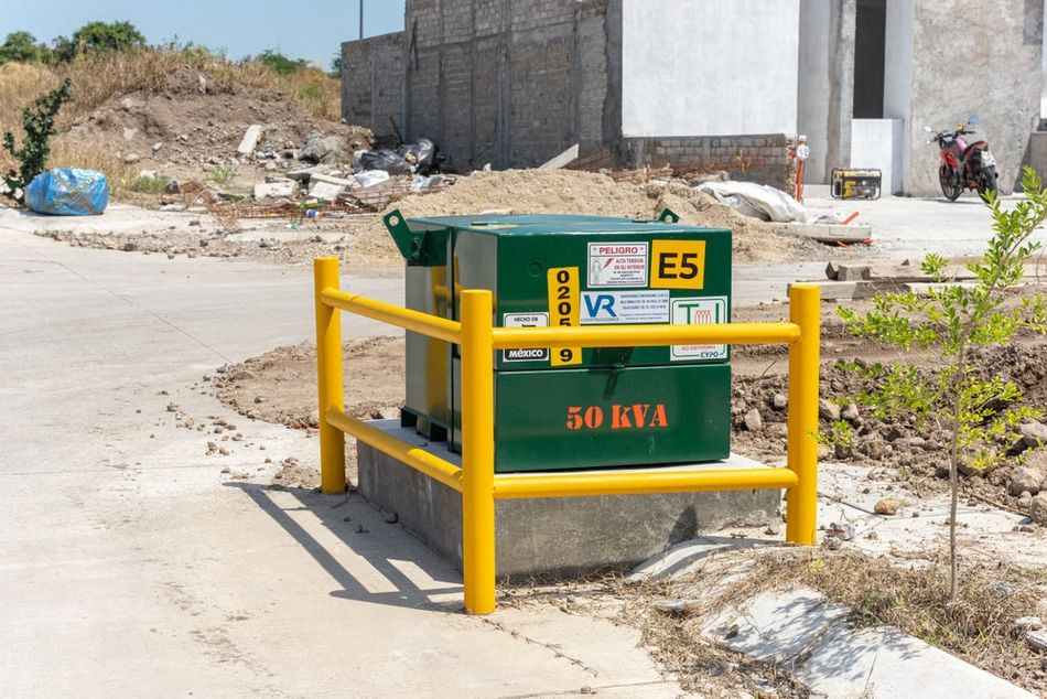
Power Transformers (Line Frequency): Used in power distribution and power supplies at 50/60 Hz (or 400 Hz in some aerospace systems). These use laminated silicon-steel cores to minimize eddy currents. They are designed for high efficiency under near-sinusoidal excitation. Construction may be single-phase or three-phase. Three-phase transformers typically have three cores combined or use a bank of single-phase units. Large power transformers (MVA range) are usually oil-immersed for cooling and have robust insulation and mechanical bracing to withstand high electromagnetic forces.
Suggested Reading: How to Select the Right Reinforced Transformer for High-Voltage Energy Storage Applications
Transformers may also be categorized by cooling method: dry-type (air-cooled) vs. oil-immersed, etc., and by usage such as distribution transformers, instrument transformers (CTs and PTs for measurement), etc. These all obey the same fundamentals with tweaks in design priorities.
Performance Metrics of Electrical Transformers
Transformers are specified by a power rating in volt-amperes (VA or kVA). It indicates how much apparent power they can deliver continuously without overheating. Key performance metrics include:
Voltage Rating
It is the rated primary and secondary voltage, usually given as RMS values at rated frequency. If the rated primary voltage is exceeded at constant frequency, it drives the core into saturation as
core flux ∝ V/f
For example, a transformer designed for 230 V@50 Hz may overheat if fed 230 V@60 Hz. Higher frequency at the same voltage reduces flux
(Φ∼V/(N·f))
so, 60 Hz operation is fine or even easier for a 50 Hz unit. But the reverse – using a 60 Hz-rated transformer on 50 Hz at the same voltage – can saturate the core.
For designers, it is a good practice to keep the V/f below the design volt-second product. Many transformers have a ±5% to ±10% voltage tolerance before saturation rapidly increases the no-load current.
Turns Ratio & Voltage Regulation
A transformer's no-load secondary voltage is determined by its turns ratio, but under load, this voltage drops due to internal impedance. This voltage regulation, the percentage difference between no-load and full-load secondary voltage, depends on winding resistance (copper loss) and leakage reactance.
Well-designed power transformers typically have 2-5% regulation, while smaller, cheaper units might see over 10% drop at full load. Higher gauge wire or interleaved windings can improve regulation, though possibly increasing size or complexity.
Efficiency (η)
Transformers are highly efficient, especially larger ones, with multi-MVA units reaching over 99.5%. Even small 50 VA transformers can achieve 90-95% efficiency at full load. Losses include constant core (iron) losses from hysteresis and eddy currents, and copper (winding) losses (I²R) that increase with load.
Designers balance core size and copper usage to optimize efficiency. DOE standards regulate minimum efficiencies for distribution transformers, promoting better core materials.
Impedance & Short-Circuit Strength
A transformer's percent impedance (%Z) signifies its voltage drop at full load and its ability to limit fault currents during a short circuit. For instance, 5% impedance means a 5% voltage drop at full load and 20 times rated current under a secondary short.
Transformers must be mechanically robust, with strong clamping and bracing, to withstand the immense electromagnetic forces generated during short-circuit events, adhering to standards like IEC 60076.
Temperature Rise
A transformer's power rating is limited by its allowable winding and core temperature rise, dictated by its insulation class (e.g., Class B = 130 °C max). Overloading drastically increases losses and heating, halving insulation life for every 10 °C over rating.
Thermal design, including natural convection, oil circulation, or forced cooling (radiators, fans), is crucial to ensure adequate heat dissipation and achieve a typical 20-30 year lifespan at rated temperatures.
Frequency Response
Important for specialized applications like audio or pulse transformers, frequency response defines the transformer's operational bandwidth. Real transformers have low-frequency cutoffs (due to magnetizing inductance) and high-frequency roll-offs. Designers widen bandwidth by using larger cores or sectional/bifilar windings.
Suggested Reading: Distributed Air Gap Cores: Standardizing High-Performance Magnetic Solutions
Integration & Interoperability
Integrating a transformer into a larger system requires careful attention to connections, grounding, and compatibility with system parameters. A fundamental aspect is wiring configuration and phasing. Each winding has two terminals (or more if taps); manufacturers usually mark one end of each winding with a dot indicating the same instantaneous polarity.
Series Connections
You can series-connect secondaries to obtain a higher voltage (e.g., two 12 V secondaries in series give 24 V). It’s crucial to connect them in phase – the dot of one to the non-dot of the other – so that the voltages add. If connected out-of-phase (dot-to-dot), the voltages subtract or cancel.
A simple way to do it is to measure the combined output with a voltmeter: if wired correctly in series, you get the sum (e.g. ~24 V); if you mistakenly get near zero, the series was out-of-phase, so swap one secondary’s leads.
Parallel Connections
Paralleling transformer outputs can supply higher current (e.g., parallel two 5 V, 2 A windings to get 5 V, 4 A). For this, the output voltages must be equal and in phase. Even a small voltage difference can cause circulating currents between transformers.
Only parallel identical transformers or windings of the same transformer. Verify phase by measuring between the two outputs before tying them: you should read ~0 V if in phase (since they’re at the same potential). If you read double the voltage, they are out of phase and must be reversed before connecting.
Suggested Reading: Types of Circuits: A Comprehensive Guide for Engineering Professionals
Grounding and Earthing
Often, one side of a transformer is grounded for safety or reference. For isolation transformers, you have the option to ground one secondary leg or leave it floating, depending on the application. In audio or RF, a floating secondary can break ground loops.
But in power systems, grounding the secondary neutral (as in a service transformer) provides a reference and fault return path. Interoperability with system grounding is critical – e.g., a Δ–Y distribution transformer provides a grounded neutral on secondary for 3-phase 4-wire loads. Always follow grounding practices per code (IEEE Green Book, NEC, etc.) for the given installation.
Impedance Matching
In systems like audio or RF, ensure the transformer's impedance ratio suits the source and load. For example, an audio output transformer might need to reflect an 8 Ω speaker as several kilohms to the tube's plate circuit – using the correct turns ratio accomplishes this.
In RF, transformers (or baluns) are used to match antenna impedance to the transmitter (50 Ω). If the mismatch is large, a transformer alone might not cover the whole bandwidth, and additional tuning may be needed.
Mechanical Integration
Mounting of transformers should account for vibration and noise. Line-frequency cores can hum (magnetostriction). Rubber isolation pads or mounts can reduce noise transmission to the chassis. Moreover, enclosures should allow heat dissipation (vents or cooling fans for dry types; if oil-filled, ensure expansion room or conservator for oil expansion).
It is also crucial to provide access for terminations – high voltage bushings on larger units or screw terminals on smaller ones – with appropriate clearances.
Interoperability with Protection
Transformers often need primary protection (fuse or circuit breaker) and sometimes secondary protection. For example, a small control transformer might have an internal fuse or rely on the upstream breaker. When connecting to the utility, ensure coordination so that a downstream fault is cleared before the transformer is damaged.
Some transformers include temperature sensors (like a thermostat or thermal fuse in small ones, or Pt100 sensors in large ones) – integrate those into an alarm or trip circuit to prevent overheating.
Tooling, Ecosystem & Standards
Building a transformer from scratch requires not only design calculations but also the right tools and materials. The ecosystem for transformer construction includes specialized suppliers of cores, wire, bobbins, and insulation. Key components and tools:
Core Materials
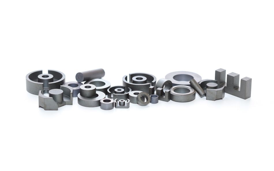
E-I laminations of grain-oriented silicon steel are commonly used for line frequency. They come in standardized sizes (identified by center leg width, e.g., "EI-150" core has a 1.50-inch center leg). These thin laminations (0.25–0.5 mm thick) are varnished or oxidized to insulate them from each other, reducing eddy currents. The laminations are stacked to build the desired core cross-section (stack thickness determines area).
For high-frequency, ferrite cores (often toroidal or EE cores) are used; they are brittle ceramic materials with very high electrical resistivity (virtually eliminating eddy currents).
Magnet Wire
Transformers are wound with enameled copper (or aluminum) magnet wire – a thin insulation coating allows tight layering.
Common wire types include polyimide enamel for high temp, or specialized self-bonding enamels, etc. The wire gauge is chosen based on current density. A typical design current density is 2.5–4 A/mm² (which is about 500–700 circular mils per amp) for power transformers to limit copper loss and temperature rise.
Insulation & Tapes
Various insulation materials separate winding layers and different windings. Polyester films (Mylar), paper (presspaper or Nomex), and insulating tapes are used. For example, Nomex paper (Aramid) is common for high-temperature class, often combined with polyester. In the Ludens example, materials included press paper and an NMN laminate (Nomex-Mylar-Nomex sandwich). These provide dielectric isolation and structural support.
Bobbin or Coil Formers
Small transformers are wound on plastic bobbins that fit the core. Larger ones might use custom-made forms or even no bobbin (windings wrapped directly with insulation and the core assembled through). The bobbin ensures proper spacing to the core and often has partitions to segregate windings. Ensure the bobbin material is rated for the operating temperature and meets creepage distance requirements.
Winding Equipment
For prototyping, a hand-crank coil winder or even a lathe can be used to wind coils (with a turns counter). Precision layer winding by hand is laborious but achievable for low-volume production. For production, there are programmable winding machines that guide the wire and count turns. It’s a good practice to maintain tension on the wire while winding to achieve tight coils. Use inter-layer insulation between each layer of wire, especially for high voltage, to avoid turn-to-turn breakdown.
Varnish & Impregnation
After winding, mains-frequency transformers are often impregnated with insulating varnish to solidify windings (preventing movement, noise, and abrasion), enhance thermal conduction, and provide moisture protection.
High-quality units use Vacuum Pressure Impregnation (VPI) for thorough void filling. Smaller transformers are dipped and baked. Varnish must match the insulation class, with proper curing crucial to avoid residual solvents.
Testing Instruments
An essential part of the ecosystem is testing. Before full use, a new transformer should undergo:
Winding resistance measurement - Check for consistency and expected I²R loss
Ratio test - Apply a low AC voltage to the primary and measure the secondary to verify the turns ratio
No-load current test - Energize primary at rated voltage, measure magnetizing current and core loss – a higher than expected no-load current could indicate a shorted turn or core issue, and
Hi-pot (dielectric) test - Applies a high voltage (typically 2–3 kV AC for one minute for mains transformers) between primary and secondary (and from windings to core) to ensure insulation integrity.
Suggested Reading: Electrical Testing: Comprehensive Guide for Engineering Professionals
Standards & Compliance
Transformers must meet relevant safety and performance standards, such as:
IEC 61558 (and its subparts) - For power transformers connected to mains. It is the international standard covering the safety of power transformers, isolating transformers, control transformers, etc., up to 1 kV class. It specifies requirements like isolation distances, temperature limits, dielectric withstand, and labeling.
UL 5085 - Practiced in the US for low-voltage transformers.
IEEE C57.12.00 - For distribution transformers) cover larger utility transformers.
DOE 2016 - Efficiency standard for distribution transformers mandating minimum efficiency at 50% and 100% load.
IEEE/ANSI and IEC 60076 - Define test methods, allowable tolerance, sound level limits, etc., for large power transformers.
Software Tools
Modern design often uses software to fine-tune. There are calculators (some provided by core manufacturers) and finite-element analysis (FEA) tools to simulate magnetic fields and hotspots. For high-frequency designs, tools can optimize the winding layout to reduce proximity effect losses.
However, for line-frequency transformers, many engineers still rely on handbook formulae and proven empirical rules (like the area product method by McLyman). Some CAD tools (e.g. SPICE) can model a transformer’s equivalent circuit to predict performance in a larger system.
Transformer Design Trade-offs & Alternatives
Transformer design involves numerous trade-offs, and in some use cases a conventional transformer may not be the optimal solution. It’s important to consider alternatives and the pros/cons:
Size vs. Frequency
Traditional low-frequency transformers are bulky and heavy. For weight-sensitive applications like aircraft or spacecraft, a high-frequency link offers an alternative. Here, AC is converted to high frequency (e.g., 20 kHz) for a much smaller transformer, similar to how a Switch-Mode Power Supply (SMPS) operates.
This drastically cuts weight—a 1 kW, 50 Hz transformer might be 10-15 kg, while an SMPS with a high-frequency transformer could be 1-2 kg. The trade-off involves:
Adding complex electronics
Managing high-frequency electromagnetic noise.
This shift is evident in consumer electronics, where bulky linear adapters have been replaced by compact switching adapters.
Efficiency vs. Simplicity
While simple transformers are very efficient at their design load (95–99%), their efficiency drops significantly under light loads due to fixed core losses. In contrast, electronic converters can dynamically adjust, often offering better light-load efficiency. Modern data centers are exploring Solid-State Transformers (SSTs), which use power electronics to replace passive transformers with AC-DC-AC converters and high-frequency transformers.
SSTs promise smaller size, lighter weight, and advanced control like instantaneous voltage regulation and bidirectional power flow for smart grids. However, they are currently complex and costly, with slightly lower large-scale efficiency (around 97–98%) compared to traditional transformers (99 %+). There's also a reliability trade-off, as passive transformers offer significantly longer lifespans.
Suggested Reading: Power System Reliability Modeling: A Step Toward Resilient Data Centers
Autotransformer vs. Isolation
An autotransformer (single winding with tap) is smaller for the same VA because part of the winding serves both primary and secondary. If isolation is not required (e.g., adjusting 120 V to 100 V for Japan-rated equipment), an autotransformer is very efficient and compact. The trade-off is safety – no isolation from the source.
Moreover, autotransformers cannot create a new neutral or change from star to delta, etc., they only scale voltages. So they are best for modest ratio adjustments on an already isolated system. Use a two-winding transformer when isolation or a large ratio change is needed.
Transformerless Power Supplies
In low-power electronics (such as cheap LED bulbs or phone chargers), designers sometimes eliminate the 50/60 Hz transformer entirely by using capacitive or resistive dropper circuits, or direct line-fed switch-mode converters. This yields an extremely compact solution, but no galvanic isolation from mains, which can be a serious safety hazard. The trade-off here is cost/size vs. safety and EMI.
Regulatory standards strictly limit where transformerless supplies can be used (usually only inside sealed equipment, double insulated and low-touch). Modern ICs often incorporate high-frequency isolation through tiny internal transformers or capacitors for signal isolation, showing that even when “no transformer” is claimed, often some form of isolation is still in play at chip scale.
Transformer Comparison Summary
Transformer Type | Pros | Cons |
Conventional Transformer | Passive, very reliable, highly efficient at rated load, provides isolation. | Heavy and large at low frequencies, fixed output (limited inherent regulation), unidirectional power flow. |
High-Frequency Transformer (in SMPS) | Much smaller and lighter, enables active output regulation, easily supports multiple outputs. | Introduces switching noise/EMI, requires more complex control circuitry, design complexity increases significantly at higher power ranges. |
Solid-State Transformer (SST) | Adds advanced features (e.g., voltage regulation, frequency conversion), significant weight savings at high power, supports smart-grid functions. | High initial cost, complex power electronics require robust cooling, still an emerging technology for large-scale distribution. |
Transformer Implementation & Deployment Best Practices
Effectively implementing and deploying transformers requires adherence to key best practices, ensuring optimal performance, safety, and longevity.
Design Calculation Workflow
Define specifications like voltage, frequency, and power, then select the core type and material early. Calculate primary turns, accounting for desired output voltage and expected voltage regulation. For instance, a 120V AC to 10V AC, 150W transformer might require around 223 primary turns and 19-20 secondary turns, adjusted for a 5% regulation margin.
Winding Strategy
A sound winding strategy can minimize leakage. Wind the primary closest to the core, then apply ample insulation before winding the secondary. Keep windings tight, even, and use margin tape to prevent shorting. Secure lead wires to the bobbin. Before core assembly, inspect for wire enamel damage.
Core Assembly
This process involves carefully inserting laminations to ensure a tight stack and minimize air gaps, which can increase magnetizing current. The core is then secured, often with clamps or bolts. Following assembly, varnish impregnation (e.g., Vacuum Pressure Impregnation for high quality) solidifies windings, enhances thermal conduction, and provides moisture protection, with proper curing being essential.
Testing
Testing instruments are crucial before deployment. Conduct winding resistance, ratio, and no-load current tests. A hi-pot (dielectric) test verifies insulation integrity. If possible, perform a full-load test to check voltage and temperature rise.
Installation
Finally, installation considerations include ensuring adequate ventilation and mechanical securing. Use correctly rated, color-coded lead wires with strain relief. Integrate appropriate protective devices like fuses or circuit breakers (e.g., primary fuse at 1.5x full-load current, slow-blow for inrush). For large units, perform specific field handling and maintenance routines like oil sampling and tank grounding. Always adhere to safety standards for clearances and test above operating conditions to ensure the transformer survives worst-case scenarios or fails safely.
Conclusion
Transformers are fundamental to electrical engineering, enabling safe and efficient electricity use globally. Building them requires a blend of theory, like Faraday's law, and practical skills in winding and insulation. Adhering to best practices in design calculations and material selection ensures reliable, long-lasting units. As grids evolve and efficiency demands rise, transformers will incorporate new technologies, yet their core principles will remain rooted in electromagnetism.
Whether crafting small audio units or large utility transformers, the discussed guidelines provide a clear roadmap. With sound engineering and craftsmanship, making a transformer is an enlightening experience. For deeper insights, consult specialized texts and standards like IEC 61558 or IEEE C57, and stay updated on new materials and simulation tools to push design boundaries.
Frequently Asked Questions (FAQ)
Why do transformers only work with AC and not DC?
Transformers rely on a changing magnetic flux to induce voltage in the secondary coil (Faraday’s law). DC provides a steady flux (once initial transients settle), so there’s no ongoing induction – the secondary sees no voltage. With DC, the core can saturate as it sees a constant magnetizing force, leading to overheating.
2. How can I reduce the humming noise of a transformer?
The hum (typically at 2× line frequency, e.g. 100 Hz or 120 Hz) comes from magnetostriction in the core and vibration of laminations or windings. To reduce it:
Ensure the core laminations are tight – use clamps or epoxy to prevent them from vibrating.
Use a core with lower flux density or better material – operating below saturation and using grain-oriented steel can minimize magnetostriction strain.
Mount the transformer on rubber pads so that any remaining vibration is isolated from the chassis.
Also, DC offset in the AC supply can cause asymmetrical magnetization and louder hum – using a DC blocking filter in the mains (for audio applications) can help if that’s an issue.
3. What is inrush current and how can I limit it?
Inrush current is the spike of current when a transformer is first energized. It occurs because the core may start unsaturated and the flux can shoot to a high level depending on the point on the AC waveform the switch is closed, plus any residual flux in the core. This can draw a current 5–10 times the normal magnetizing current for a few cycles. To limit inrush, several strategies exist:
Pre-insertion resistors or NTC thermistors in series – at turn-on, they add resistance and then either are shorted out or naturally heat up and reduce resistance.
Sequential energization – for three-phase units, closing breakers phase-by-phase or at the instant of voltage zero-crossing can mitigate worst-case flux jump.
Soft-start circuits – in electronics, using a triac or SSR to ramp the voltage or using a primary-side inrush limiter circuit.
4. How do I select the right core size for my transformer?
Core selection is guided by the required power (VA) and operating frequency. A quick method is the area product method: determine the product of core cross-sectional area and window area (space for windings) needed for your VA, given current density and flux density assumptions. McLyman’s handbook provides the essential formulas for deciding the right core size for transformers.
5. What causes a transformer to fail and how can I prevent it?
Common failure modes:
Overheating – excessive load or poor cooling leads to insulation breakdown.
Insulation degradation – overvoltage surges or aging can break down insulation between windings or turns, causing shorts.
Manufacturing defects – e.g. burrs in laminations causing shorts, or mis-layered winding causing a turn short.
Vibration & mechanical stress – large transformers under short-circuit can experience forces that deform windings, leading to turn shorts or displacement.
Moisture ingress – especially in oil-filled or outdoor transformers, moisture can reduce insulation resistance and cause dielectric failure.
References
Understanding Transformer Design Principles & Parameters [Internet]. Chint Global. [cited 2025 Jun 9]. Available from: https://www.chintglobal.com/sa/en/about-us/news-center/blog/understanding-transformer-design-principles-parameters.html
Introduction to Transformers Standard E-I Construction [Internet]. Talema. [cited 2025 Jun 9]. Available from: https://talema.com/introduction-to-transformers-standard-e-i-construction/
Different Types of Transformers and Their Applications [Internet]. Circuit Digest. [cited 2025 Jun 9]. Available from: https://circuitdigest.com/tutorial/different-types-of-transformers-and-their-applications
Different Transformer Types [Internet]. Daelim Belefic. [cited 2025 Jun 9]. Available from: https://daelimbelefic.com/different-transformer-types/
Jang H, Kim H. Design of high-frequency power transformer for isolated LLC resonant converter with high power density. SciDirect [Internet]. 2023 Sep 15 [cited 2025 Jun 9];27:100859. Available from: https://www.sciencedirect.com/science/article/pii/S2215098623001179
Billingsley RH, Lollar TL. High power, high frequency transformer design and optimization. NASA Technical Reports Server [Internet]. 1977 May 1 [cited 2025 Jun 9]. Report No.: 19770017440. Available from: https://ntrs.nasa.gov/citations/19770017440
Best Practice Manual - Transformers [Internet]. Electrical Engineering Portal. [cited 2025 Jun 9]. Available from: https://electrical-engineering-portal.com/download-center/books-and-guides/electrical-engineering/best-practice-manual-transformers
Transformer Designs [Internet]. Daelim Belefic. [cited 2025 Jun 9]. Available from: https://daelimbelefic.com/transformer-designs/
in this article
1. Key Takeaways:2. Introduction3. Foundational Principles & Terminology4. Transformer Architecture & Variants5. Performance Metrics of Electrical Transformers6. Integration & Interoperability7. Tooling, Ecosystem & Standards8. Transformer Design Trade-offs & Alternatives9. Transformer Implementation & Deployment Best Practices10. Conclusion11. Frequently Asked Questions (FAQ)12. References