Electrical Transformers: Engineering Fundamentals, Design Parameters, and Emerging Trends
This article provides a Comprehensive guide to transformer theory, design, sizing, smart technologies, and practical selection for engineers.

31 Mar, 2026. 11 minutes read
Key Takeaways
Transformers operate via electromagnetic induction, where alternating magnetic flux in an iron core induces voltage in a secondary winding proportional to the turns ratio.
Engineering design considers turns ratio, kVA rating, impedance (typically 2 to 6%), cooling class (e.g., ONAN, ONAF) and standards like IEC 60076 and IEEE C57.
Step-up, step-down, isolation, autotransformer, instrument (CT/PT) and specialized variants serve different functions. Emerging solid-state transformers use power electronics and wide-bandgap devices for high-frequency operation.
Laminated silicon-steel cores minimize eddy current losses; amorphous metal cores reduce no-load losses by up to 70%. Efficient cooling and low impedance reduce I2R losses during long-distance power transmission.
Digital integration via IEC 61850 Edition 2.1 and solid-state designs enable grid monitoring, reactive power control and bidirectional power flow. However, high cost, reliability and standardization remain challenges.
Practical selection: Engineers must evaluate kVA requirements, voltage levels, regulation, impedance, cooling class, environmental conditions and burden (for instrument transformers) to choose the right transformer for safe and reliable operation.
Introduction
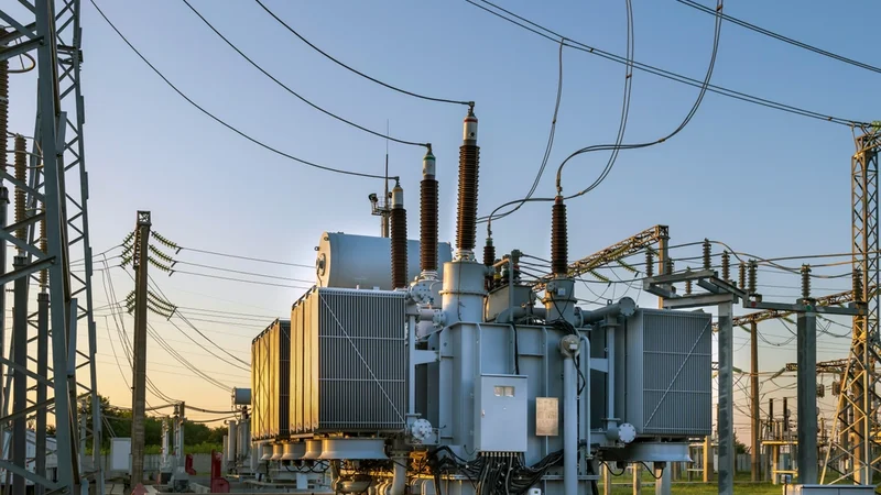
Transformers are an indispensable component of modern electrical infrastructure. They enable efficient electrical conversion between voltage levels to ensure smooth transmission of electricity, powering sensitive electronics, isolation of circuits, and safe distribution. Without them, the global power grid could not deliver high-voltage transmission and low-voltage utilization economically.
At their core, transformers exploit electromagnetic induction: a changing magnetic field within a laminated iron core induces a corresponding voltage in a secondary winding. The turns ratio between primary and secondary coils determines whether the transformer steps the voltage up or down. This principle underlies devices as small as audio isolation transformers and as large as 1000 kV power transformers feeding national grids.
This technical article provides an authoritative engineering reference on electrical transformers, targeting design engineers, hardware developers, and technicians. After reviewing theoretical concepts, we will explore practical design parameters, standard types, loss mechanisms, materials, and cooling methods. We then discuss instrument transformers, solid-state and smart transformers, and selection criteria aligned with international standards. Emerging trends such as amorphous metal cores and IEC 61850 digital communication are highlighted.
Fundamental Theory and Operating Principles
Electromagnetic Induction and Mutual Coupling
Transformers operate on the principle of electromagnetic induction, first formalized by Faraday and refined for alternating-current systems. When alternating current (AC) flows through the primary winding, it generates a time-varying magnetic flux in the transformer core.
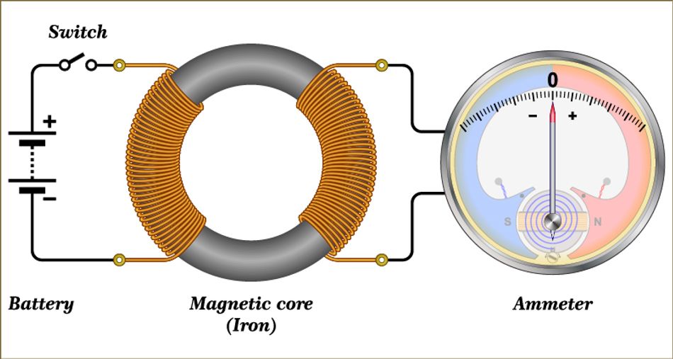
This alternating magnetic field links the secondary winding via mutual inductance, inducing an electromotive force (EMF) proportional to the rate of change of flux.
The induced secondary voltage is:

where Np and Ns are the number of turns in the primary and secondary coils. Under ideal conditions, the voltage ratio equals the turns ratio:

This equation indicates that transformers are passive devices. They do not create energy; they transform voltage and current while conserving power (neglecting losses).
A step-down transformer has n less than 1, reducing voltage while increasing current.
A step-up transformer has n greater than 1, raising voltage for long-distance transmission and reducing current to minimize resistive losses.
Since AC flux is necessary, transformers do not operate with direct current (DC).
Magnetic Core and Flux Path
The core is a critical component in the process of mutual induction. It channels magnetic flux between windings. Laminated silicon-steel or grain-oriented steel cores with high permeability reduce magnetizing current and confine flux.
Laminations are insulated to restrict eddy current paths; typical lamination thickness ranges from 0.23 to 0.35 mm for power transformers.
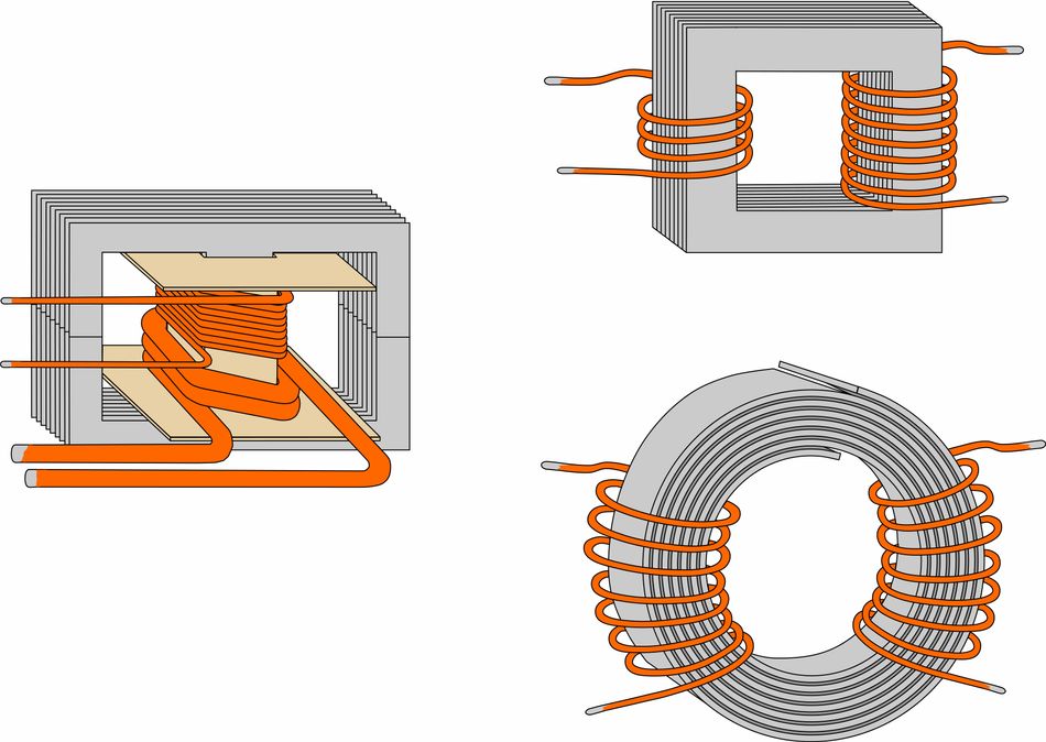
The core may be arranged as:
Core-type: Windings surround part of the core limbs. Suitable for high-voltage applications.
Shell-type: Core surrounds windings, offering better leakage reactance control. Often used in distribution transformers.
Toroidal: A continuous ring core with uniformly distributed windings, providing low leakage inductance and compact size but more complex manufacturing.
Leakage Flux and Equivalent Circuit
Not all flux links both windings; some leakage flux follows alternative paths in the surrounding air. Leakage flux behaves like a series of inductances in the transformer's equivalent circuit. The simplified steady-state equivalent circuit includes:
Primary winding resistance and leakage reactance
An ideal transformer represents perfect coupling and a turns ratio
Magnetizing branch with core loss resistance and magnetizing reactance, accounting for hysteresis and eddy current losses
Secondary winding resistance and leakage reactance are referred to the primary via the square of the turns ratio
Losses: Hysteresis, Eddy, and Copper
Real transformers exhibit losses:
Core (iron) losses: Hysteresis loss arises from magnetization reversal of the core. Eddy current loss arises from induced currents within lamination cross-sections. Use of thin laminations and high-resistivity materials (silicon steel, amorphous metal) reduces these losses.
Copper (winding) losses: Resistive I2R losses occur in the primary and secondary windings. Design aims to balance copper cost against losses for the expected duty cycle.
Stray losses: Caused by leakage flux inducing currents in nearby structural components. Proper core clamping and shielding minimize these losses.
Suggested Reading: How to Make a Transformer: Engineering Principles and Best Practices
Transformer Types and Applications
Power Transformers
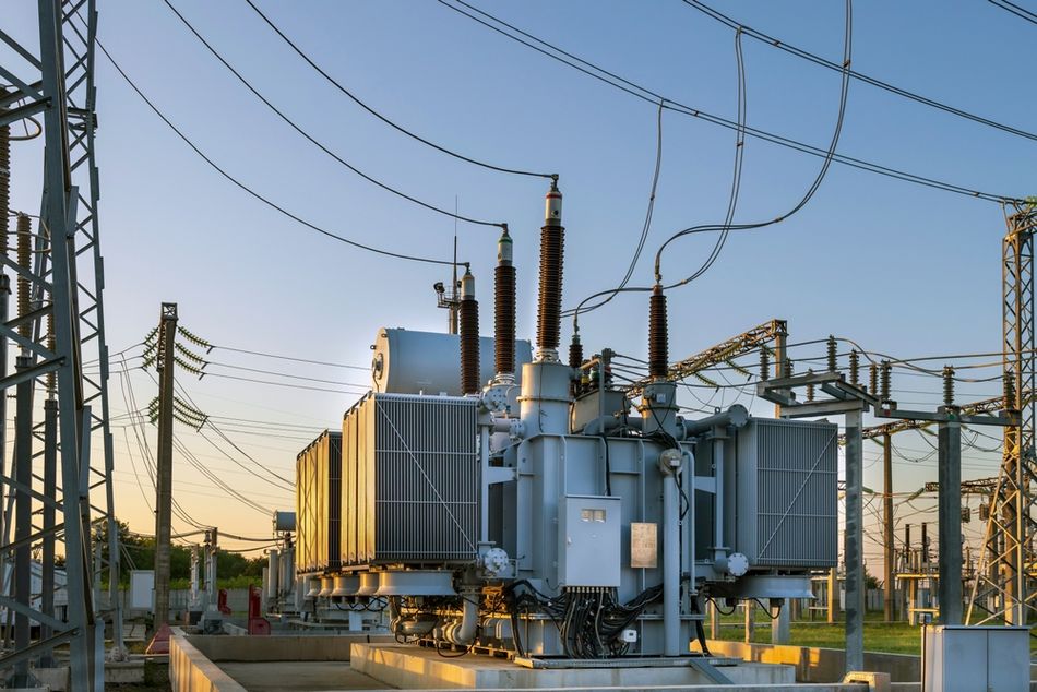
Power transformers handle high power ratings (hundreds of kVA to MVA) and voltages up to hundreds of kilovolts. They connect generation and transmission networks, enabling efficient long-distance power line transmission.
According to the turns ratio principle, stepping voltage up to high levels reduces current and therefore I2R losses over long distances.
Key standards for transformer design include IEC 60076 (power transformers) and IEEE C57 series, which specify:
Ratings
Insulation levels
Dielectric tests
Cooling classes
Temperature rise limits
Sound levels.
Design Parameters of a Transformer
Parameter | Consideration | Example |
Rated power (kVA/MVA) | Determined from load requirements; oversizing increases cost and no-load losses | 25 kVA to 500+ MVA |
Primary/secondary voltage | Based on grid levels | 400 kV/110 kV transmission, 11 kV/400 V distribution |
Impedance (Z) | Typically 2 to 6%; influences short-circuit current and voltage regulation | Higher impedance limits fault current but increases voltage drop |
Cooling class | Based on rating and installation conditions | ONAN up to ~50 MVA; ONAF for 50 to 100 MVA; OFAF/ODAF for larger |
Connection group | Delta, star or zig-zag; determines phase shift and harmonic suppression | Y-delta typical for transmission step-down |
Distribution Transformers
Distribution transformers supply low-voltage energy to residential, commercial and industrial loads. Ratings range from 25 kVA to 5 MVA. They are designed for high efficiency at partial load since loads vary widely. Transformers work unattended outdoors on poles or pads; robust design and insulation are critical.
Dry-type transformers use cast-resin or vacuum-pressure impregnated (VPI) windings and are preferred in buildings for fire safety. They have higher no-load and load losses than oil-immersed units but avoid fire hazards.
Autotransformers
An autotransformer shares part of its winding between primary and secondary, saving copper and weight. Voltage ratio is achieved by tapping at an intermediate point on the continuous winding. Autotransformers are efficient and economical for small voltage differences (e.g., 132 kV/110 kV). However, they lack isolation; common-mode faults can propagate, limiting use in safety-critical applications.
Recent designs integrate power electronics for dynamic voltage regulation, enabling smart grid compatibility. Advanced insulation materials improve reliability under transients, while digital monitoring using IoT sensors enhances fault prediction, condition-based maintenance, and operational efficiency in modern substations.
Isolation and Instrument Transformers
Isolation transformers provide galvanic isolation between circuits, often with a 1:1 turns ratio. They protect sensitive equipment from ground loops, transients, and noise, and are used in laboratory and medical devices.
Instrument transformers scale current or voltage to safe levels for measurement and protection:
Current transformers (CTs) produce secondary currents (typically 5 A or 1 A) proportional to the primary current.
Voltage transformers (VTs) or potential transformers (PTs) output reduced voltages (e.g., 110 V) for metering.
The burden of a CT (the connected impedance of meters, relays, and leads) must be within rated limits (e.g., 5 to 35 VA). Too high or too low a burden degrades accuracy; accuracy is guaranteed only between 25% and 100% of the rated burden.
Specialized Transformers
Variable-frequency transformers exchange power between AC systems of different frequencies.
Arc-furnace transformers feature large regulating ranges and robust construction.
Traction transformers in locomotives supply traction motors with variable voltage.
Phase-shifting transformers adjust the phase angle between networks, controlling power flow.
Grounding transformers provide a neutral point for grounding ungrounded systems.
Suggested Reading: What Is Ground in a Circuit? Understanding Grounding Concepts and Implementations
Materials and Core Technologies
Silicon Steel and Grain-Oriented Laminations
The majority of power transformers use cold-rolled grain-oriented (CRGO) silicon steel laminations. Alloying silicon (~3.5%) increases electrical resistivity and reduces hysteresis losses.
Grain orientation aligns magnetic domains along the rolling direction, thereby lowering core loss. Laminations are coated with insulation varnish to minimize interlamination eddy currents.
Amorphous Metal Cores
Amorphous metal, produced by rapid cooling of molten alloys (Fe-B-Si) into thin ribbons (~25 um), lacks long-range crystalline order. Its high electrical resistivity and low magnetic coercivity lead to significantly lower hysteresis and eddy losses. Amorphous core transformers exhibit no-load losses up to 70% lower than conventional cores.
Additional benefits include reduced carbon emissions and longer life due to lower operating temperature. However, amorphous cores are brittle and difficult to handle; they require careful manufacturing and may exhibit higher audible noise and lower mechanical strength.
Nanocrystalline and Other Novel Materials
Nanocrystalline alloys (e.g., Fe-Cu-Nb-Si-B) offer even lower core loss at higher frequencies, with high permeability and saturation flux density. They are used in high-frequency transformers and inductors. Powdered iron and ferrite cores appear in small transformers and switch-mode power supplies.
Cooling Methods and Temperature Management
Classification of Cooling Systems
Transformer cooling classes follow IEC 60076-2 and IEEE C57.12.00 codes. Each four-letter code indicates internal and external cooling mediums and their circulation modes:
Code | Internal Medium | Internal Circulation | External Medium | External Circulation | Typical Application |
ONAN | Mineral oil | Natural convection | Air | Natural convection | Up to ~50 MVA distribution and substation |
ONAF | Mineral oil | Natural convection | Air | Forced (fans) | 50 to 100 MVA power transformers |
OFAF/ODAF | Oil | Forced | Air | Forced | Large power transformers |
AN/AF | Air (dry type) | Natural/forced | Air | Natural/forced | Dry-type indoor transformers |
Temperature Rise and Insulation Classes
Insulation materials are rated by thermal class (A = 105 C, B = 130 C, F = 155 C, H = 180 C). Proper cooling design ensures the hot-spot temperature does not exceed the insulation class, guaranteeing the expected service life. Standards require routine temperature rise tests and specify ambient conditions for rating (e.g., 40 degrees C ambient, 1000 m altitude).
Practical Design and Selection
Sizing and kVA Calculation
Selecting an appropriate transformer starts with determining the apparent power requirement:
kVA = P_load / Power Factor
where P_load is the real power in kilowatts (kW) and the power factor (PF) is between 0 and 1. Over-specifying kVA increases cost and no-load loss; under-specifying leads to overheating and reduced life. Distribution units are often sized so that the average loading is 40 to 60% of rated kVA.
Impedance and Voltage Regulation
Impedance influences fault level and voltage regulation. For typical applications, recommended impedances are:
2 to 3% for long feeders, to minimize voltage drop and maintain regulation.
3 to 5% for balanced loads such as heating or lighting.
5 to 6% for motor-heavy loads to limit inrush and short-circuit currents.
Parallel operation requires matching impedances within ±7.5 %.
Selection Checklist
The following table summarizes the preferences while selecting a transformer.
Voltage ratings | Primary and secondary voltages plus tap range |
kVA/MVA rating | Calculated from load demand and future growth |
Frequency | Typically 50 Hz or 60 Hz |
Cooling class | Choose ONAN/ONAF/ODAF based on rating and installation conditions |
Impedance and voltage regulation | Determine acceptable voltage drop and short-circuit current |
Efficiency and losses | Evaluate the total cost of ownership |
Environmental factors | Altitude, ambient temperature, enclosure type, noise limits |
Standards and certification | IEC 60076, IEEE C57 and local regulations |
Accessories | On-load tap changer, monitoring sensors, pressure relief devices, bushings |
Advanced Developments: Solid-State and Smart Transformers
Solid-State Transformers (SSTs)
Conventional transformers operate at line frequency (50/60 Hz) and rely on heavy magnetics. Solid-state transformers integrate power electronic converters and high-frequency transformers to achieve greater control and compactness. An SST typically comprises three stages:
Input AC-DC stage: Converts grid AC to DC using rectifiers/inverters with wide-bandgap semiconductors like silicon carbide (SiC) or gallium nitride (GaN).
Isolation DC-DC stage: A high-frequency transformer (often using ferrite or amorphous alloys) provides galvanic isolation and voltage conversion.
Output DC-AC stage: Converts DC back to controlled AC at the desired voltage and frequency, enabling bidirectional power flow and voltage regulation.
Advantages of Solid State Transformers include reactive power compensation, harmonic control, voltage sag mitigation, bidirectional power flow for renewable integration, and compatibility with both AC and DC grids.
However, SSTs face challenges, such as the high cost of power electronics, reliability concerns, electromagnetic interference, and the need for new standards.
Suggested Reading: EMI Mitigation in High-Density Designs with Ultra-Thin Inductors and High-Current Ferrite Beads
Smart Transformers and Digital Communication
Smart transformers integrate sensors, digital controllers, communication interfaces and sometimes solid-state modules. They monitor temperature, oil level, dissolved gases, load current, and power quality. Data are transmitted via standards such as IEC 61850 using GOOSE messaging and Sampled Value communication.
IEC 61850 Edition 2.1 (mandatory for certification since January 2024) provides enhanced interoperability, IPv6 support, and cybersecurity features. Smart transformers can autonomously adjust tap positions, optimize voltage profiles, detect incipient faults, and coordinate with distributed generation.
Emerging Materials and Future Trends
3D-printed magnetic cores and additive manufacturing of windings
Nanocrystalline and amorphous cores combined with high-frequency switching for compact SSTs
High-temperature superconducting transformers for dramatically reduced losses
Digital twin modeling using sensor data and machine learning
Eco-friendly fluids (natural esters and synthetic fluids) replacing mineral oil per IEC 61099 and IEC 62770
Suggested Reading: Innovative Transformer Solution Addresses Traditional Challenges
Conclusion
Electrical transformers remain the backbone of power systems engineering. From the fundamental physics of electromagnetic induction and magnetic flux to the practical realities of kVA sizing, impedance selection, and cooling class specification, these devices demand both theoretical understanding and hands-on engineering judgment.
Laminated iron core designs continue to dominate, but amorphous metal cores offer up to 70% lower no-load losses for distribution applications. Solid-state transformers represent a paradigm shift, enabling bidirectional power flow, reactive power compensation and compatibility with DC grids, though cost and reliability challenges persist. Smart transformers with IEC 61850 communication transform passive magnetic devices into intelligent grid nodes.
For engineers selecting transformers, the checklist of voltage, kVA rating, impedance, cooling, insulation, and standards compliance provides a structured approach. As the power grid integrates more renewables, energy storage, and electric vehicles, transformers will continue to evolve in materials, control, and digital connectivity.
FAQs
1. What is the purpose of a transformer?
A transformer modifies AC voltage and current levels while maintaining the same frequency and approximate power. It enables efficient long-distance transmission by stepping up voltage (reducing current and I2R losses) and later stepping down voltage for safe utilization. Transformers also provide isolation between circuits and interface measurement devices.
2. How does turns ratio affect voltage and current?
The turns ratio Ns/Np determines the ratio of secondary to primary voltage. A ratio greater than one produces a higher secondary voltage (step-up), whereas a ratio less than one produces a lower secondary voltage (step-down). Current transforms inversely: Is/Ip = Np/Ns.
3. Why are laminated cores used?
Laminations increase core resistance and reduce eddy current losses. Each lamination is insulated from its neighbors, breaking conduction paths. Laminated silicon steel also reduces hysteresis loss, improving efficiency. Thinner laminations are used in high-frequency transformers to further reduce losses.
4. What are the differences between ONAN, ONAF and ODAF cooling?
ONAN (Oil-Natural, Air-Natural) relies on natural convection in oil and air; it is sufficient up to about 50 MVA. ONAF adds forced air via fans, suitable up to ~100 MVA. ODAF or OFAF uses pumps to force oil circulation and fans for air, enabling higher ratings.
5. How do I select the appropriate current transformer burden?
Specify a CT with a burden rating higher than the total impedance of connected instruments and leads. Operating outside 25 to 100% of rated burden reduces accuracy. Consider secondary resistance, cable length and instrument input when calculating burden.
6. What advantages do amorphous core transformers offer?
Amorphous metal cores exhibit significantly lower no-load losses (up to 70%) and load losses (up to 30%) compared with conventional silicon steel. They provide high efficiency, lower operating temperature and reduced carbon emissions. Drawbacks include brittleness, higher weight and increased noise.
7. Are solid-state transformers ready for widespread deployment?
Solid-state transformers offer benefits like bidirectional power flow, reactive power compensation and compact size. However, high cost, reliability concerns and the need for new standards limit widespread adoption. Pilot projects are ongoing, particularly for smart grids, EV charging and rail traction.
References
B. Carlson, “Transformer basics and transformer principles,” Basic Electronics Tutorials. [Online]. Available: https://www.electronics-tutorials.ws/transformer/transformer-basics.html
Ayr Energy, “Transformer cooling classes: Guide for ROI & reliability,” Ayr Energy, Dec. 3, 2025. [Online]. Available: https://www.ayr.energy/resource/blog/transformer-cooling-class-guide
Electrical‑World, “Transformer sizing & kVA calculator | Load calculation guide,” Electrical‑World, Sep. 9, 2025. [Online]. Available: https://electrical-world.com/posts/transformer-sizing-complete-guide-with-calculations
TheElectricalGuy, “What is a CT burden? Complete guide to current transformer burden explained,” TheElectricalGuy, Feb. 21, 2026. [Online]. Available: https://www.theelectricalguy.in/switchgear/what-is-ct-burden-current-transformer/
A. Chandran and A. Kumar, “Solid state transformers: A comprehensive review of technology, topologies, applications, research gaps, and future directions,” Sci. Res. Publ., Jun. 25, 2025. [Online]. Available: https://www.scirp.org/journal/paperinformation?paperid=143590
Enlit World, “IEC 61850 Ed. 2.1: A new milestone in smart grid interoperability,” Enlit World. [Online]. Available: https://www.enlit.world/library/iec-61850-ed-2-1-a-new-milestone-in-smart-grid-interoperability
Powerstar, “Amorphous core transformer: Everything you need to know,” Powerstar, 2023–2025. [Online]. Available: https://powerstar.com/blog/amorphous-core-transformer/
in this article
1. Introduction2. Fundamental Theory and Operating Principles3. Transformer Types and Applications4. Materials and Core Technologies5. Cooling Methods and Temperature Management6. Practical Design and Selection7. Advanced Developments: Solid-State and Smart Transformers8. Conclusion9. FAQs1. What is the purpose of a transformer?11. References