PCB Inspection: Ensuring Quality and Reliability in Electronics Manufacturing
This article delves into the significance of PCB inspection, exploring the latest advancements, challenges, and various inspection techniques employed to safeguard the integrity and functionality of PCBs.

21 May, 2024. 14 minutes read
Introduction
PCB inspection is a critical process in electronics manufacturing that ensures the quality and reliability of each board before it becomes part of an electronic device. PCBs must be free from defects to guarantee the reliability and optimal performance of the end products. Effective PCB inspection can significantly reduce the risk of failures, enhance product longevity, and maintain high customer satisfaction.
The impact of thorough PCB inspection extends beyond just quality control; it plays a pivotal role in the overall manufacturing process. By identifying and addressing defects early, manufacturers can avoid costly rework, reduce waste, and maintain compliance with industry standards. This not only saves time and resources but also ensures that the final products are of the highest quality, meeting both industry standards and consumer expectations.
Understanding PCB Inspection
What is PCB Inspection?
PCB inspection is the process of examining circuit boards in the manufacturing phase to identify any defects or errors that could impact the functionality and quality of the final electronic products. Given the complexity and miniaturization of modern electronics, even minor defects can lead to significant failures, making thorough inspection indispensable. This inspection ensures that the PCBs are built to design specifications and are free from defects that could cause device failure.

There are several types of PCB inspections, each with its specific applications and advantages:
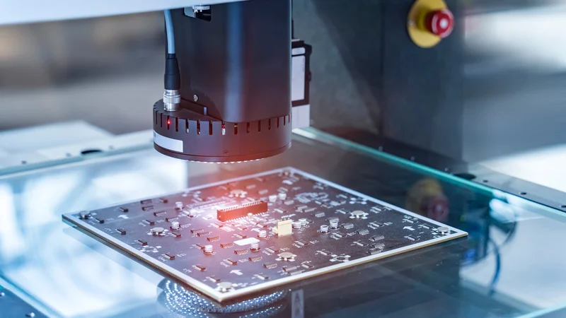
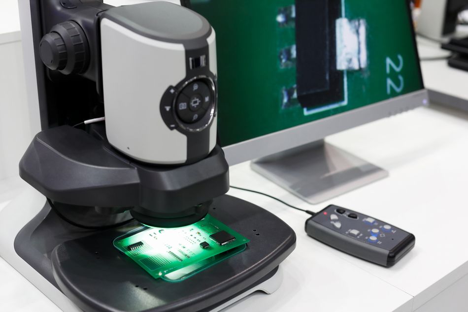
Visual Inspection: This is the simplest form of PCB inspection, where human inspectors visually examine the PCB for obvious defects such as misaligned PCB components, soldering errors, vias and visible cracks. This can be done manually by technicians or by using high-resolution cameras. Historically, manual visual inspection was the primary method used, but it has limitations in terms of speed and accuracy, especially for complex boards. It is typically used in the early stages of the production process or for simple boards where defects are more apparent.
Automated Optical Inspection (AOI): AOI uses high-resolution cameras and image processing software to automatically inspect PCBs for defects. [1] It is highly effective for detecting issues such as solder bridge defects, component placement errors, and surface defects. AOI systems have evolved significantly, incorporating advanced algorithms and machine learning to improve detection accuracy. AOI is commonly used in high-volume production environments due to its speed and precision.
X-ray Inspection: This method uses X-rays to inspect PCB, allowing for the detection of hidden defects such as voids in solder joints, internal cracks, and misaligned layers. The use of Computed Tomography (CT) in advanced X-ray systems provides detailed 3D images, enabling thorough analysis of internal structures. X-ray inspection is particularly useful for complex, multilayer PCBs where visual and AOI methods may not be sufficient.
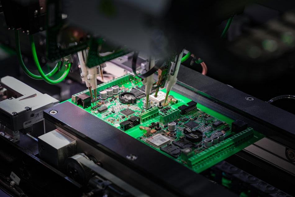
In-Circuit Testing (ICT): ICT involves testing the electrical functionality of the PCB by checking the resistance, voltage, and signal output of various components to ensure they are operating correctly. It's an automated process that utilizes a specialized test fixture equipped with probes to make electrical contact with individual components on the PCB.
Each type of inspection has its specific applications in different stages of PCB manufacturing. By implementing a thorough PCB inspection strategy, manufacturers can significantly improve product quality, reduce production costs, and ensure their electronic devices function smoothly.
Recommended Reading: Mastering PCB Testing: Techniques, Methods, and Best Practices Unveiled
Importance of PCB Inspection in Manufacturing
Printed circuit boards (PCBs) act as the intricate highways upon which electrical signals travel, connecting and coordinating the various components within a device. But just like a building needs a strong foundation, a well-functioning PCB requires meticulous inspection throughout the manufacturing process. PCB inspection plays a crucial role in this process, acting as a safeguard against defects that could compromise the functionality and longevity of electronic devices.
Common defects that PCB inspection can detect include:
Solder Joint Defects: Poor solder joints can lead to intermittent connections or complete circuit failures. These defects can occur due to insufficient solder, excessive solder, or improper soldering techniques. For example, in the automotive industry, a faulty solder joint in a vehicle's electronic control unit can lead to critical system failures, posing safety risks.
Component Misalignment: Misaligned components can cause short circuits, open circuits, or mechanical stress on the PCB. This can result from inaccurate placement during the assembly process. In consumer electronics, such as smartphones, misaligned components or connectors can lead to device malfunctions and reduced product lifespan.
Trace Defects: Issues such as broken traces, shorts, or insufficient trace width can disrupt the electrical pathways on the PCB, leading to malfunctioning circuits. [2] In medical devices, trace defects can compromise the accuracy and reliability of critical diagnostic equipment.
Delamination: Separation of the PCB layers can occur due to poor lamination processes or thermal stress, compromising the structural integrity and electrical performance of the board. In aerospace applications, delamination can lead to catastrophic failures, making thorough inspection essential.
Voids in Solder Joints: Voids can weaken solder joints, making them more susceptible to mechanical stress and thermal cycling, which can lead to premature failure. In high-reliability sectors like telecommunications, voids in solder joints can result in network outages and service disruptions.
By identifying and addressing these defects through rigorous PCB inspection processes, manufacturers can ensure that their products meet the highest standards of quality and reliability. This ultimately enhances customer satisfaction and reduces the risk of costly failures.
Key Technologies in PCB Inspection
Automated Optical Inspection (AOI)
Automated Optical Inspection (AOI) is a non-contact, automated technique used in PCB inspection to visually assess the quality and identify defects on printed circuit boards. Imagine a machine with a keen eye, meticulously scrutinizing each board for imperfections. That's essentially what AOI systems do, employing advanced optics, cameras, and image processing software.

AOI works by using a combination of lighting techniques, high-resolution cameras, and advanced algorithms. The lighting illuminates the PCB from various angles, ensuring that all features are visible. AOI systems capture detailed images of the PCB and compare them against a predefined set of standards or a "golden" reference board. [3] This comparison allows the system to identify discrepancies such as missing components, soldering defects, and misalignments. The evolution of AOI technology has significantly enhanced the efficiency and accuracy of PCB inspection.
More advanced AOI systems incorporate machine learning models to improve detection accuracy and adapt to new defect types over time. Historically, the introduction of machine learning has allowed AOI systems to learn from past inspections, continuously improving their performance.
The advantages of AOI include:
High Speed and Efficiency: AOI systems can inspect PCBs much faster than manual inspection, making them ideal for high-volume production environments. For example, in the production of consumer electronics like smartphones, AOI ensures rapid and accurate inspection of thousands of units per day.
Consistency and Accuracy: AOI provides consistent inspection results, reducing the variability associated with human inspectors. The use of advanced algorithms and machine learning models enhances the accuracy of defect detection. In the automotive industry, this consistency is crucial for maintaining the reliability of electronic control units.
Non-Destructive Testing: AOI is a non-contact, non-destructive method, meaning it does not damage the PCB during inspection. This is particularly important in the medical device industry, where the integrity of the PCB must be preserved.
However, AOI also has some limitations:
Initial Setup and Calibration: Setting up an AOI system requires significant time and expertise to calibrate the cameras and lighting, and to program the inspection criteria. This initial investment can be a barrier for smaller manufacturers.
Complexity in Detecting Certain Defects: AOI may struggle with detecting defects that are not easily visible on the surface, such as internal layer issues or very fine cracks. In such cases, supplementary inspection methods like X-ray inspection may be necessary.
Examples of specific AOI systems and their capabilities include:
Mirtec MV-6 OMNI Series: Integrates both 2D and 3D inspection capabilities, allowing precise Z-axis height measurement of components. It detects component shift, lift, missing parts, and soldering issues like insufficient solder and bridging.
Omron VT-S730: This system uses 3D imaging and advanced pattern-matching algorithms to detect a wide range of defects, including solder joint issues and component misalignments. It is known for its high speed and accuracy, making it suitable for large-scale production lines.
Koh Young Zenith 2: The Zenith series incorporates machine learning models to enhance defect detection and reduce false positives. It offers high-resolution 3D inspection, providing detailed analysis of solder joints and component placement. This system is widely used in the telecommunications industry to ensure the reliability of network equipment.
CyberOptics SQ3000: This AOI system features multi-reflection suppression (MRS) technology, which minimizes false calls by accurately distinguishing between actual defects and noise. It is particularly effective in inspecting complex PCBs with high component density, such as those used in aerospace applications.
By leveraging these advanced AOI systems, manufacturers can ensure that their PCBs meet stringent quality standards, ultimately enhancing the reliability and performance of their electronic products.
X-ray Inspection
X-ray inspection is a powerful technique used in PCB inspection to detect hidden defects that are not visible through traditional optical methods. By utilizing X-rays, this method can penetrate the layers of a PCB, revealing internal structures and identifying issues such as voids in solder joints, internal cracks, and misaligned layers. The ability to see inside the PCB without disassembling it makes X-ray inspection invaluable for ensuring the integrity and reliability of complex, multilayer boards.
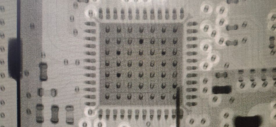
The principles of X-ray inspection are based on the differential absorption of X-rays by different materials. When X-rays pass through a PCB, materials with higher atomic numbers, such as metals, absorb more X-rays. They appear darker in the resulting image, while materials with lower atomic numbers, such as the PCB substrate, appear lighter. [4] This contrast allows for the detailed visualization of internal features and the identification of defects. Historically, the introduction of X-ray inspection has allowed manufacturers to detect and address issues that were previously undetectable, significantly improving product reliability.
Comparing X-ray inspection with other inspection methods highlights its unique advantages and limitations:
| Inspection Method | Advantages | Limitations |
| Visual Inspection | Simple, Low Cost | Limited to Surface Defects, Subjective |
| Automated Optical Inspection (AOI) | High Speed, Accurate for Surface Defects | Cannot Detect Internal Defects |
| X-ray Inspection | Detects Hidden/Internal Defects, Non-Destructive | Higher Cost, Requires Specialized Equipment |
The physics of X-ray imaging involves the generation of X-rays using an X-ray tube, where electrons are accelerated and collide with a metal target, producing X-rays. These X-rays then pass through the PCB and are captured by a detector, which converts the X-rays into a digital image. The resulting image provides a detailed view of the internal structure of the PCB, allowing for the identification of defects that are not visible on the surface. For example, X-ray inspection is crucial for ensuring that every layer of a multilayer PCB is correctly aligned and free from internal defects that could lead to catastrophic failures.
X-ray inspection can reveal a variety of defects, including:
Voids in Solder Joints: Voids can weaken solder joints, making them more susceptible to mechanical stress and thermal cycling.
Internal Cracks: Cracks within the PCB layers can compromise the structural integrity and electrical performance of the board.
Misaligned Layers: Misalignment of internal layers can lead to electrical shorts or open circuits, affecting the functionality of the PCB.
Advanced X-ray inspection systems often incorporate Computed Tomography (CT) to provide even more detailed analysis. CT involves taking multiple X-ray images from different angles and reconstructing them into a 3D model of the PCB. This 3D visualization allows for a comprehensive examination of the internal structures, making it easier to identify and analyze defects. CT is particularly useful in high-reliability applications, such as aerospace and medical devices, where the highest level of inspection accuracy is required. For instance, in the medical device industry, CT scans of PCBs ensure that life-saving equipment operates flawlessly by detecting and addressing any internal defects.
X-ray inspection is an invaluable tool in electronics manufacturing, providing a critical check on the quality and integrity of PCBs and other components where other inspection methods fall short. By leveraging its capabilities, manufacturers can ensure that their PCBs are free from hidden defects.
Emerging Technologies in PCB Inspection
Recent advancements in PCB inspection technologies have significantly enhanced the accuracy and efficiency of defect detection. Machine Learning (ML) and Artificial Intelligence (AI) are at the forefront of these innovations. These technologies are transforming the landscape of PCB inspection by enabling precise identification of defects, reducing false positives, and adapting to new defect types over time. The integration of ML and AI into PCB inspection systems represents a significant leap from traditional methods, offering unprecedented levels of accuracy and adaptability.
Machine learning algorithms, particularly those based on deep learning, are being integrated into PCB inspection systems to improve their performance. Deep learning models, such as Convolutional Neural Networks (CNNs), are trained on vast datasets of PCB images to recognize patterns and anomalies that indicate defects. [5] These models can learn from both labelled and unlabeled data, continuously improving their accuracy as they process more images.
For example, a CNN can be trained to detect solder joint defects by analyzing thousands of images of both defective and non-defective joints. These neural networks learn to distinguish subtle differences that may be missed by traditional inspection methods. This capability has revolutionized the inspection process, making it more reliable and efficient.
AI-driven inspection systems also leverage advanced image processing techniques to enhance defect detection. These systems use algorithms to preprocess images, enhancing contrast and highlighting features that are indicative of defects. This preprocessing step is crucial for improving the accuracy of the subsequent analysis performed by the AI models. Additionally, AI models can be designed to prioritize certain types of defects based on their impact on the PCB's functionality. This targeted approach improves the inspection process and also helps in maintaining the high quality of the products.
3D X-ray and Laser Scanning technologies offer a more comprehensive view of the PCB. This helps in the detection of defects related to component height, solder joint volume, and other 3D aspects that might be missed by traditional 2D inspection methods. 3D imaging provides greater depth perception, enabling more precise defect identification and reducing false positives from 2D inspection techniques.
Advanced Non-Destructive Testing (NDT) Methods utilize terahertz waves to penetrate PCBs and analyze their internal structure. It holds promise for detecting hidden defects like delamination, cracks, and voids within electronic components, offering a non-destructive alternative to traditional X-ray methods. This technique uses high-frequency sound waves to create detailed images of the PCB's interior. It can potentially detect defects like cracks, voids, and weak solder joints, providing valuable insights for high-reliability applications.
These emerging technologies are setting new standards for what’s possible in PCB inspection. These innovations are driving improvements in product quality, reducing costs, and meeting the increasing demands of modern electronics manufacturing. As PCBs continue to evolve in complexity and function, these innovative inspection technologies will become even more vital to the industry.
Recommended Reading: What is AOI (Automated Optical Inspection): A Comprehensive Guide
Challenges in PCB Inspection
Common Challenges and Limitations
PCB inspection faces several common challenges and limitations that can impact the efficiency and effectiveness of the inspection process. Stringent PCB inspection is crucial in the manufacturing process to prevent defects that could lead to product failures, recalls, and damage to brand reputation. Understanding these challenges is vital for developing strategies to mitigate their effects and improve overall inspection outcomes.
One of the primary challenges in PCB inspection is the occurrence of false positives and false negatives. False positives occur when the inspection system incorrectly identifies a defect where none exists, leading to unnecessary rework and increased production costs. Conversely, false negatives occur when the system fails to detect an actual defect. This allows faulty PCBs to pass through the inspection process and potentially reach the market. These errors can be attributed to limitations in imaging resolution and algorithmic accuracy. For instance, in high-volume consumer electronics manufacturing, false negatives can result in defective products reaching customers, leading to costly recalls and loss of consumer trust.
Another significant challenge is the speed of inspection. High-volume production environments require rapid inspection processes to keep up with manufacturing demands. However, increasing the speed of inspection can sometimes compromise accuracy, leading to missed defects or incorrect identifications. Balancing speed and accuracy is a constant challenge for PCB inspection systems. In automotive manufacturing, the production lines operate at high speeds. Any inspection delay can create bottlenecks, reducing overall efficiency.
Common challenges in PCB inspection include:
False Positives/Negatives: Incorrect identification of defects or failure to detect actual defects.
Inspection Speed: The need for rapid inspection processes in high-volume production environments.
Imaging Resolution: Limitations in the resolution of imaging systems can affect the ability to detect small or subtle defects.
Algorithmic Accuracy: The precision of defect detection algorithms can vary, impacting the reliability of the inspection process.
Complexity of PCBs: As PCBs become more complex with higher component densities and multiple layers, the difficulty of accurately inspecting them increases.
The impact of these challenges on manufacturing processes can be significant. False positives can lead to unnecessary rework, increasing production time and costs. False negatives can result in defective products reaching the market, damaging brand reputation and leading to costly recalls. Slow inspection speeds can create bottlenecks in the production line, reducing overall manufacturing efficiency.
Technical details on the sources of these challenges include:
Imaging Resolution: The resolution of imaging systems is critical for detecting small defects. Higher-resolution cameras can capture more detail, but they also require more processing power and time to analyze the images. For example, in the semiconductor industry, high-resolution imaging or magnification is essential for detecting minute defects in microchips.
Algorithmic Accuracy: The accuracy of defect detection algorithms depends on their ability to correctly interpret the captured images. Machine learning models, such as convolutional neural networks (CNNs), can improve accuracy by learning from large datasets, but they require extensive training and validation to perform reliably. In the aerospace industry, these algorithms must be meticulously trained to ensure no defects are missed.
Complexity of PCBs: Modern PCBs often feature high component densities and multiple layers, making it challenging to inspect all aspects of the board accurately. Advanced inspection systems, such as those incorporating 3D imaging and X-ray technology, can help address these challenges but come with higher costs and complexity. In medical device manufacturing, these advanced systems are crucial for ensuring product safety and efficacy.
By understanding and addressing these common challenges and limitations, manufacturers can enhance the effectiveness of their PCB inspection processes, ensuring higher quality and reliability in their electronic products.
Recommended Reading: How Do Circuit Boards Work: A Comprehensive Guide to the Heart of Electronics
Conclusion
In this article, we have explored the critical aspects of PCB inspection, including its importance in ensuring product quality and reliability, the various inspection technologies available, and the common challenges faced in the inspection process. Staying updated with the latest advancements in PCB inspection technologies, such as machine learning and AI, is essential for maintaining high standards in electronics manufacturing. By implementing effective inspection strategies, manufacturers can significantly reduce the risk of defects, enhance product longevity, and ensure customer satisfaction.
Frequently Asked Questions (FAQs)
Q. What are the most common defects detected by PCB inspection?
A. The common defects are:
Solder Joint Issues: Poor solder joints can lead to intermittent connections or complete circuit failures. These defects can occur due to insufficient solder, excessive solder, or improper soldering techniques. Solder joint issues can cause unreliable operation and potential device failure.
Component Misalignment: Misaligned components can cause short circuits, open circuits, or mechanical stress on the PCB. This can result from inaccurate placement during the assembly process. Misalignment can lead to device malfunctions and reduced product lifespan.
Trace Defects: Issues such as broken traces, shorts, or insufficient trace width can disrupt the electrical pathways on the PCB, leading to malfunctioning circuits. Trace defects can compromise the accuracy and reliability of the PCB's functionality.
Q. How does automated optical inspection (AOI) differ from manual inspection?
A. AOI uses high-resolution cameras and image processing software to automatically inspect PCBs for defects. It employs pattern-matching algorithms and machine learning models to detect issues such as solder joint defects and component placement errors. Manual inspection relies on human inspectors to visually examine the PCB, which can be subjective and less consistent.
Q. What are the benefits of using X-ray inspection for PCBs?
A. X-ray inspection offers several advantages, particularly for detecting hidden defects that are not visible through traditional optical methods. It can penetrate the layers of a PCB, revealing internal structures and identifying issues such as voids in solder joints, internal cracks, and misaligned layers. X-ray inspection complements other methods by providing a non-destructive way to inspect the internal features of complex PCBs.
Q. How can machine learning improve PCB inspection processes?
A. Machine learning enhances PCB inspection accuracy and efficiency by enabling more precise and faster identification of defects. For instance, deep learning models, such as convolutional neural networks (CNNs), are trained on vast datasets of PCB images to recognize patterns and anomalies that indicate defects. These models continuously improve their accuracy as they process more images.
References
[1] Wevolver. What is AOI (Automated Optical Inspection): A Comprehensive Guide [Cited 2024 May 21] Available at: Link
[2] Mclpcb. Guide to Common PCB Issues & Failures [Cited 2024 May 21] Available at: Link
[3] ResearchGate. A Review and Analysis of Automatic Optical Inspection and Quality Monitoring Testing Methods in Electronics Industry [Cited 2024 May 21] Available at: Link
[4] Emsginc. X-Ray PCB Inspection [Cited 2024 May 21] Available at: Link
[5] MDPI. Analysis of Training Deep Learning Models for PCB Defect Detection [Cited 2024 May 21] Available at: Link