Microstepping Explained: Full Step, Half Step & Microstep
How microstepping works in stepper motors, the incremental torque cost of each resolution, and why finer microsteps do not improve positioning accuracy.

23 Aug, 2026. 15 minutes read
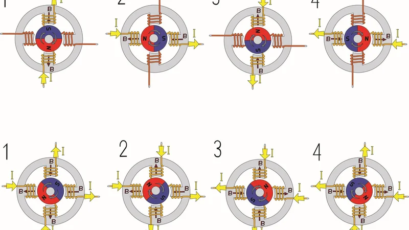
Full stepper control of the stepper motor
Key Takeaways
Micro stepping works by driving the two windings with sine and cosine current waveforms 90 electrical degrees apart, so the stator flux vector rotates in fine increments instead of jumping in discrete steps. 8
Incremental torque per microstep falls as sin(90° / microsteps per full step). At 16 microsteps per full step you get under 10% of the full-step holding torque per microstep, and at 1/256 you get 0.61%. 2
Resolution is not accuracy. Detent torque of 5% to 20% of holding torque, bearing friction torque, and non-sinusoidal motor geometry mean a commanded microstep often produces no shaft motion at all. 2,4
The real payoff is vibration and resonance control: moving from full-step mode to 1/32 microstepping cuts the per-step excitation energy from 100% to roughly 0.1%. 4
Choose microstep resolution for smoothness, then use a closed-loop system, a finer step angle motor, or better mechanics when you genuinely need positioning accuracy.
Introduction
Every stepper motor application eventually runs into the same question: how many microsteps should you configure? The marketing answer is "as many as your stepper motor drivers support." The engineering answer depends on what you are actually trying to fix.
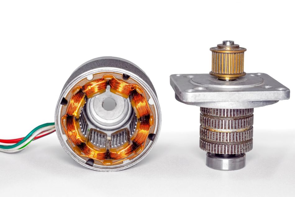
Stepper motor, disassembled, with the rotor set aside
Start with the basic idea. A stepper motor normally moves in fixed increments, "full steps", determined by how many teeth its rotor and stator have. Microstepping doesn't add more teeth or change the motor's mechanics. Instead, it changes how the driver sends current to the windings, letting the rotor settle at intermediate positions between full steps. Think of it less like adding gears and more like dimming a light: the hardware is the same, only the control signal is finer.
By definition, microstepping is a current-control technique that commands intermediate rotor positions by proportioning current between two motor windings
This article covers the fundamentals of microstepping, stepping modes, the mathematics of winding current and incremental torque, what real driver silicon does, what independent measurements show, and how to pick a mode for your machine.
Stepper Motor Fundamentals
A hybrid stepper motor combines a permanent magnet rotor with a toothed stator, producing a large number of stable detent positions per revolution. The most common industrial variant has a 1.8° step angle, which gives exactly 200 steps per revolution.
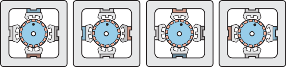
Unlike most electric motors, which are commanded by voltage or torque and run continuously, a stepper is commanded in discrete steps and normally runs open loop. Stepper motors are brushless: they have no commutator making mechanical contact, so they must be electronically commutated, and a conventional two-phase stepper motor has two stator electromagnets, each driven by its own H-bridge. 1
In a bipolar stepper, current in each winding can flow in either direction, which means each winding can independently push or pull the rotor. The rotor doesn't respond to either winding in isolation; it aligns with the combined magnetic flux vector the two windings produce together. 4 That single fact is what makes microstepping possible: if you can vary the relative current in each winding, you can steer the resultant flux vector to any angle, not just the fixed 90°/45° positions used in full- and half-step drive.
The theoretical holding torque follows the magnitude of that current vector:
T_H = k × sqrt(I_A² + I_B²)
If phase currents I_A and I_B form an ideal sine and cosine pair, the magnitude stays constant and holding torque is theoretically independent of flux direction.4
Recommended Reading: H Bridge Motor Driver: Complete Engineering Guide to Topologies, ICs, and PCB Layout (2026)
Full-Step Mode, Half-Step Mode, and Microstepping Compared
Full-step Mode
In full-step mode, both windings carry full current and the driver switches polarity in a four-state sequence. The flux vector jumps 90 electrical degrees at a time, which is why full-step motion is loud and prone to resonance.1
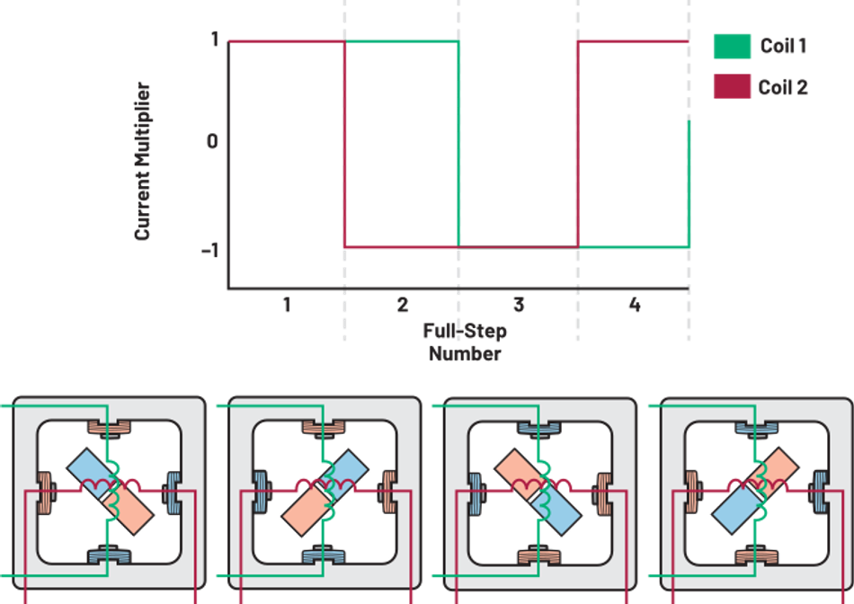
Half-step Mode
Half-step mode inserts a state between each pair of full-step positions, halving the mechanical step angle. Older drivers created half steps by alternating one-phase-on and two-phase-on states, which produces uneven torque between positions.4
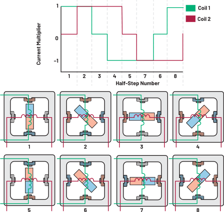
Modern drivers avoid uneven half-step torque by never fully switching a phase off. Instead of stepping between 0% and 100% current, an intermediate half-step position can use current levels near sin(22.5°) ≈ 38.3% and cos(22.5°) ≈ 92.4% of rated current, smoothing the torque transition between full-step positions. 10
Microstepping
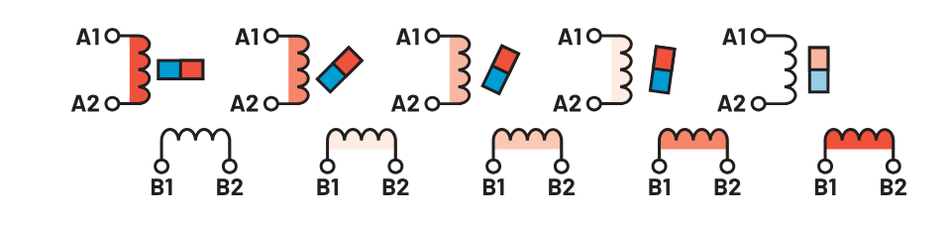
Microstepping generalizes this: rather than a handful of discrete steps, the driver approximates a continuous sine wave by changing the current ratio of the two windings in fine gradations, holding the rotor at intermediate angles.7
Mode | Steps per revolution (1.8° motor) | Effective step angle | Per-step excitation energy | Typical use |
Full-step mode | 200 | 1.8° | 100% | Low-cost indexing, high torque per step, noisy |
Half-step mode | 400 | 0.9° | 29.2% | Simple smoothness improvement over full step |
1/4 step | 800 | 0.45° | 7.6% | General-purpose motion, good torque retention |
1/8 step | 1,600 | 0.225° | 1.9% | Balanced smoothness and torque |
1/16 step | 3,200 | 0.1125° | 0.48% | 3D printers, desktop CNC, common default |
1/32 step | 6,400 | 0.05625° | 0.12% | Quiet low-speed motion, resonance suppression |
1/256 step | 51,200 | 0.00703° | 0.002% | Silent operation, usually via interpolation |
Excitation energy figures are from the relationship (4 × T_H / n) × [1 − cos(φ_e)], where φ_e is the electrical step angle, and n is the number of full steps per revolution.4
Recommended Reading: What Is a CNC Router? An Introduction for Engineers
How a Microstepping Driver Controls Winding Current
The driver never controls the position directly. It controls winding current, and the rotor follows. The defining change from full-step operation is that a phase is no longer fully on or fully off, but partially on, with sine waves applied to phase A and phase B 90° apart.8
This is the mechanism behind the article's central claim: since the driver is only ever commanding current ratios, not physical angles, the "resolution" it promises is a resolution of current steps, not a guarantee of where the shaft actually lands. Everything below is about how that current gets delivered, and where it goes wrong.
A microstep driver regulates the current in each full bridge using a current-sense resistor, a reference voltage, and an internal DAC whose output is sequenced by the translator. On the Allegro A4988, the maximum trip current is set by:
I_TripMAX = V_REF / (8 × R_S)
Each microstep then commands a percentage of that maximum.6
Some drivers let you shape this current profile more freely than others. Texas Instruments describes generating arbitrary microstep resolution by modulating the VREF analog inputs with a DAC output from a microcontroller.
In principle, this allows up to 4,096 current levels, "far much more than most applications should require".1 Sine is the standard current shape, but it can be any shape: one way manufacturers compensate for magnetic non-linearity in a specific motor.
Sine Waves, Lookup Tables, and Step Sequencing
Internally, drivers store the waveform as a table. On the TMC2209, a full electrical revolution (four mechanical full steps) is divided into 1,024 table entries. The exact step width the driver advances through that table (256, 128, or 64 entries) is what defines full, half, or quarter stepping. 5
Full-step positions land at table entries 128, 384, 640, and 896, where both coils carry 70.7% of amplitude, the RMS value of the sine, and the same figure the A4988 table shows at its own 45° "home" position, confirming this isn't chip-specific but a general property of two-phase sine microstepping.5,6
Texas Instruments implements the same idea with smaller, 512-entry tables using a divider factor instead of a fixed table size: mechanically identical concept, different bookkeeping.1
Current Chopping and Decay Modes
Getting the commanded current into an inductive winding quickly, and back out again, is where practical microstepping accuracy is won or lost. Current that lags the commanded value shifts the actual flux angle away from the intended microstep position, which is the direct source of the position error described in the introduction.
The A4988 illustrates the problem well. It uses fixed off-time PWM: when the sense voltage reaches the DAC output, the comparator resets the PWM latch and the bridge enters a decay interval. The driver automatically picks the decay mode based on which direction the current is heading: mixed decay (31.25% fast decay, then slow decay for the remainder of the off-time) when commanded current is falling, slow decay when it's rising or holding steady. This reduces the waveform distortion caused by motor back EMF.6
There's one further wrinkle worth knowing, especially at low speed. With little back EMF to slow the current rise, current can spike too fast and cause missed steps. Pulling the A4988's ROSC pin to ground forces mixed decay on both rising and falling currents and fixes the off-time at 30 µs, a direct, practical fix for that specific failure mode.6
Chopper architecture also shapes acoustic behavior, not just accuracy. Trinamic's StealthChop2 and SpreadCycle modes on the TMC2209 target quiet operation and stable current regulation respectively, and the part drives up to 2 A per coil.5
Recommended Reading: BLDC Motor Controller: Comprehensive Design Guide for Engineers
Incremental Torque: The Number Every Designer Should Check
Every stepper motor produces its rated holding torque only when both windings are at full current, exactly at a full-step position. A microstep is, by definition, a partial-current position, and partial current means partial torque.
Working against that reduced torque are three things: the load the motor is driving, friction torque from the bearings, and detent torque, the small residual torque a stepper's permanent-magnet rotor produces even with no current applied at all, from the rotor's magnetic attraction to the stator teeth.
If the sum of these exceeds what a single microstep can produce, the shaft does not move until enough additional microsteps accumulate to overcome them.
Here is where intuition usually fails. Dividing a step into 256 parts does not give you 256 equally-usable positions, because the torque that holds the rotor at each intermediate position shrinks with the microstep angle.
The incremental torque produced by a single microstep follows:
T_incremental = T_H × sin(90° / µPFS)
where T_H is the full-step holding torque and µPFS is the number of microsteps per full step. FAULHABER publishes the resulting table directly2:
Microsteps per full step | Percent of full-step torque per microstep |
1 (full step) | 100.00% |
2 (half-step mode) | 70.71% |
4 | 38.27% |
8 | 19.51% |
16 | 9.80% |
32 | 4.91% |
64 | 2.45% |
128 | 1.23% |
256 | 0.61% |
At 16 microsteps per full step, one microstep commands under 10% of the holding torque. FAULHABER states the consequence plainly: if load torque plus the motor's friction torque and detent torque exceeds the incremental torque of a microstep, "successive microsteps will have to be realized until the accumulated torque exceeds" that total. 2 Taking a microstep does not mean the motor will actually move.
Direction reversal is worse. The shaft torque must swing from its current positive value all the way to a negative value large enough to drive motion the other way, so a large number of microsteps can pass before anything happens.2
Why Microstepping Does Not Improve Positioning Accuracy
Detent Torque and Friction Torque
The incremental torque figures above explain a real consequence: at fine microstep resolutions, forces that are trivial at full-step operation become large enough to matter. Two of these are always present, even on an unloaded motor.
Bearing friction resists any movement at all. Detent torque, the residual torque a stepper's permanent magnet rotor produces from its own attraction to the stator teeth even with zero current applied, is typically 5% to 20% of holding torque, and can either add to or subtract from the torque a microstep produces, depending on rotor position. FAULHABER's application note is direct about the result: this undermines overall accuracy.2
Any external load adds a further effect. FAULHABER calls this "magnetic backlash," the displacement of the rotor away from its intended position under load, which corrects only once enough incremental torque accumulates to pull it back.2
Datasheet Accuracy Is Specified at the Wrong Positions
Manufacturers typically specify step accuracy as a relative figure such as ±5% of one full step, or an absolute figure such as ±1°. This is normally specified only for two-phase-on stop positions, meaning positions where both windings carry equal current. That figure says nothing about accuracy at intermediate microstep positions, and optimizing a motor for high full-step accuracy and holding torque generally makes its microstepping behavior worse.4
The scale of the mismatch is easy to underestimate. Consider a 7.5° permanent magnet stepper driven at 1/32 microstepping. One microstep is 7.5° ÷ 32, or 0.23°. With a typical ±1° step accuracy specification, the deviation between two two-phase-on positions can reach 8.5 microsteps.4
Accuracy beyond the manufacturer's specification is possible by calibrating each individual motor: storing a correction value for every two-phase-on stop position and outputting adjusted winding currents to compensate. This requires a rotor home position indicator to synchronize the rotor with the compensation profile. 4 The technique has a real limitation, though: if the load changes from what it was during calibration, the correction table can produce worse results than not using one at all.2
Microstepping Position Ripple and Torque Ripple
Real motors do not have ideal sine and cosine behavior. Varying air gap area, air gap distance, and magnetic hysteresis mean the flux vector's direction and magnitude both deviate from theory. The result is microstepping position ripple: the average deviation of actual microstep stop positions from theoretical ones. For a 57 mm, 7.5° permanent magnet stepper, measured clockwise ripple was 1.65°, or 22% of a full step.4
Microstep lengths from half to three times nominal "are not uncommon" when driving at 1/32 without compensation, and holding torque ripple typically runs 10% to 30% of nominal two-phase-on holding torque.4
Magnetic hysteresis adds a further complication: in a high-resolution application, stop-position hysteresis can be several times the nominal microstep length. This is why some systems always approach a target position from the same direction, keeping the hysteresis on one consistent side rather than letting it vary.4
What Measurement Shows
An independent test mounted a mirror on a motor shaft and reflected a static laser off it toward a wall 6 m away, photographing the beam's position after each commanded microstep. Because the reflection angle doubles with mirror rotation, this setup magnifies small angular deviations enough to measure them accurately. Three popular stepper motor drivers were tested at 16 microsteps per full step, both unloaded and with a 1,000 g·cm load (roughly 0.1 N·m).9
Unloaded, the Allegro A4988 was the most linear, staying within about ±1 microstep of its ideal position. The Toshiba TB6560AHQ reached about ±2 microsteps, with reproducible non-linearities. The Texas Instruments DRV8825 performed worst: near the half-step position, it jumped almost to the next full-step position within a single microstep, in both directions of travel.9
Under the applied load, both the A4988 and TB6560AHQ deflected by more than half a full step, already exceeding the resolution their 1/16 microstep setting was meant to provide.9
That is the practical summary: microstepping delivers command resolution, not guaranteed shaft positioning accuracy.
What Microstepping Actually Buys You
Vibration, Noise, and Resonance
This is the real justification, and it is substantial.
A stepper motor system has a natural frequency determined by rotor and load inertia J_T, holding torque T_H, and the number of full steps per revolution n:
F_0 = sqrt(n × T_H / J_T) / 4π
Near F_0, and often near its integer multiples and fractions, a lightly damped system risks losing steps or generating noise. With a non-microstepping driver, the main excitation is the flux vector moving discontinuously, 90 or 45 electrical degrees at a time, which pulses energy into the rotor.4
Half-stepping cuts that excitation energy to roughly 29% of the full-step value. At 1/32, only about 0.1% remains, small enough to be absorbed by internal motor friction so no ringing or overshoot is generated.4
Above two to three times the system's natural frequency, microstepping has little effect on rotor movement, because rotor and load inertia act as a low-pass filter. 4 This is why many machines interpolate microsteps at low speed and gain nothing from fine resolution at high speed.
Smoother Low-Speed Motion
In full-step or half-step mode at low stepping frequencies, motion is visibly discontinuous with significant ringing. Microstepping extends usable, quiet stepping frequencies down toward 0 Hz.4
Practical Benefits Beyond Resolution
FAULHABER lists the genuine reasons to microstep: reduced mechanical noise, gentler mechanical actuation, and fewer resonance problems. 2 The reduced excitation improves confidence in maintaining synchronization in an open-loop system and reduces wear on belts, couplings, and a ball screw or leadscrew driving the load.
Taken to the limit, an infinite number of microsteps per full step is simply two-phase synchronous permanent magnet AC operation, with the rotor lagging the rotating field by whatever angle the load demands.2
Choosing a Microstepping Mode
Design goal | Recommended approach | Reasoning |
Maximum torque per step, cost-sensitive indexing | Full-step mode or 1/4 step | Incremental torque stays at or above 38% of holding torque 2 |
Quiet 3D printers and desktop CNC | 1/16 step, or lower input resolution with driver interpolation | Excitation energy drops to about 0.5% of full step without overloading the controller 4 |
Silent operation at low speed | 1/32 to 1/256, ideally interpolated in the driver | Excitation energy becomes negligible; step pulse rate stays manageable 4 |
Genuine positioning accuracy requirement | Closed-loop stepper, 0.9° motor, or servo motors | Microstepping cannot correct detent torque, hysteresis, or mechanical error 2,4 |
High step rates from a modest microcontroller | Coarse step input plus driver interpolation | Avoids the pulse frequency ceiling while keeping smooth current 5 |
Interpolation deserves emphasis because it resolves the main practical objection to fine microstepping. The TMC2209's MicroPlyer produces microsteps at 256x resolution from each input step edge, interpolating based on the previous step interval, so anywhere from 2 up to 256 microsteps are driven per input pulse. 5
Your microcontroller sends full steps or 1/16 steps; the motor sees a 256-microstep current waveform. The caveat is that MicroPlyer only works properly with a jitter-free step frequency, and below roughly 12 Hz input at a 12 MHz clock the driver declares standstill. 5
Recommended Reading: Servo Motor: How It Works, Types, Specifications, and Sizing
Microstepping with Arduino and a Stepper Motor Driver
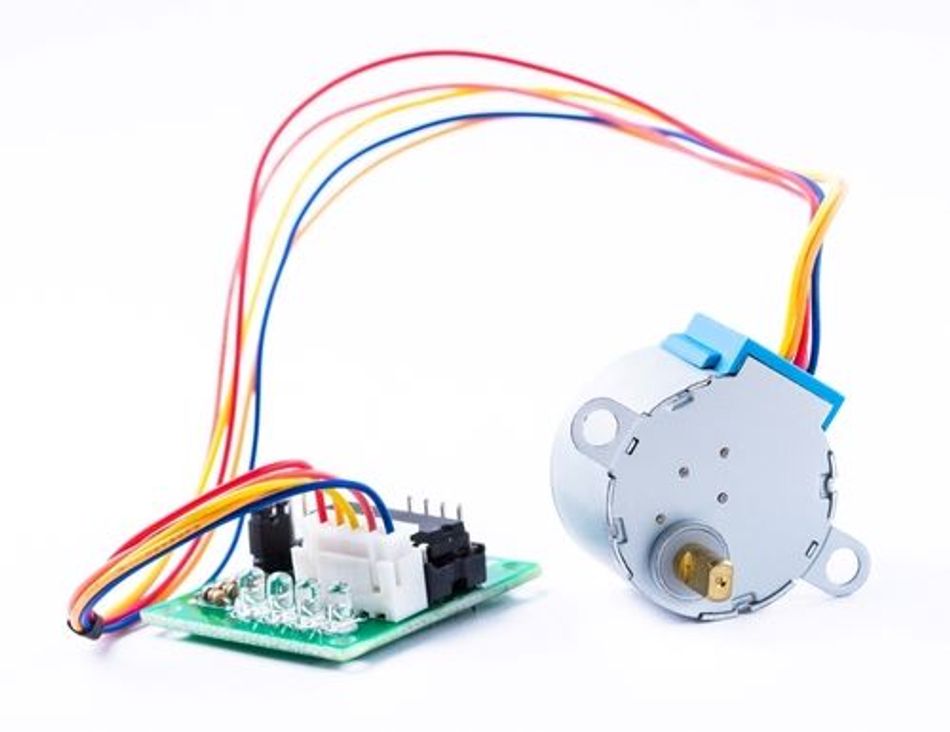
The most common hands-on introduction is an Arduino paired with an A4988 or similar step and direction module.
Set the microstepping mode. On the A4988, three logic inputs select resolution. All low gives full step; MS1 high gives half step; MS2 high gives quarter step; MS1 and MS2 high gives eighth step; all three high gives sixteenth step. Common carrier boards expose these as jumpers.6
Set the current limit before connecting the motor. Measure V_REF at the potentiometer and apply I_TripMAX = V_REF / (8 × R_S) using your board's sense resistor value. 6 Running a stepper motor above its rated winding current is the fastest way to overheat it.
Wire the bipolar stepper motor correctly. Identify the two coils with a multimeter before connecting; a miscabled winding produces vibration and no useful rotation.
Generate step pulses. The A4988 needs a minimum 1 µs high and 1 µs low on STEP, with 200 ns setup and hold on mode and direction inputs. 6 An Arduino stepping library handles acceleration profiles so you do not stall at startup.
Recalculate your steps per unit. At 1/16 microstepping, a 1.8° motor needs 3,200 pulses per revolution rather than 200 steps per revolution. Firmware for 3D printers stores this as a steps-per-millimeter value that must be updated whenever you change mode.
Change resolution only at a full-step position (both windings at equal, matched current) if absolute position must be maintained. The A4988's internal home reference differs by resolution setting, so switching modes elsewhere in the cycle can introduce an uncompensated position shift. 6
Recommended Reading: How to 3D Print: A Quick-Start Guide for Engineers
Common Mistakes and Troubleshooting
Expecting accuracy to scale with resolution. It does not. Improved accuracy is not realized simply by adding microsteps, as FAULHABER states directly. 2
Ignoring the load. If the mechanism has meaningful friction torque or a static load, fine microsteps may produce no motion until several accumulate. Symptoms include stepwise "catching up" motion at very low feed rates. 2
Using a motor optimized for the wrong thing. Motors with teeth shaped for extra flux at two-phase-on positions have large deviations from sine and cosine behavior and should be avoided in microstepping applications.4
Calibrating with a lookup table under one load and running under another. If the load torque changes after the table is generated, results can be worse than with no compensation at all. 2
Hitting the pulse rate ceiling. At 1/256 on a 1.8° motor you need 51,200 pulses per revolution, so 300 rpm demands 256 kHz. Use driver interpolation instead of brute-forcing pulses from the microcontroller. 5
Blaming the motor for a decay mode problem. Non-linearity concentrated near half-step positions, or missed steps at very low speed, usually points at current regulation and decay configuration rather than the motor itself. 6,9
Forgetting hysteresis when homing. Always approach a critical position from the same direction, since stop-position hysteresis can exceed the nominal microstep length several times over. 4
Conclusion
Microstepping is one of the highest-value techniques available in open-loop motion control, provided you buy it for the right reason. It transforms the acoustic and dynamic behavior of a stepper motor by removing the discontinuous energy pulses that excite resonance, and it extends usable low-speed operation dramatically.
What it does not do is turn a 1.8° hybrid stepper motor into a precision positioner. Incremental torque falls as the sine of the microstep angle, detent and friction torque set a floor on what a commanded microstep can achieve, and the motor's own geometry introduces position ripple that no amount of resolution corrects.
Configure microstepping for smoothness, size your motor so that incremental torque comfortably exceeds friction and detent torque in the resolution you choose, and reach for closed-loop control or better mechanics when the specification is genuinely about accuracy.
Frequently Asked Questions
What is microstepping in a stepper motor?
Microstepping is a driving technique where stepper motor drivers energize the two windings with partial, precisely controlled currents rather than switching them fully on or off. Because the rotor aligns with the resultant flux vector, intermediate current ratios hold it between the motor's natural full-step positions.
How many microsteps per full step should I use?
For most machines, 1/8 or 1/16 captures nearly all of the vibration benefit while keeping incremental torque reasonable and the pulse rate manageable. Going finer is worthwhile mainly for silent low-speed operation, and is best done with driver-side interpolation.
Does microstepping reduce holding torque?
Full holding torque is still available at two-phase-on positions, since the current vector magnitude is unchanged. What shrinks is the incremental torque generated by a single microstep, which falls to 9.80% of full-step torque at 1/16 and 0.61% at 1/256.
Does microstepping improve positioning accuracy?
No. Resolution increases, but accuracy does not, and may decrease. Detent torque of 5% to 20% of holding torque, bearing friction, magnetic hysteresis, and non-sinusoidal torque versus rotor position all limit where the shaft actually stops.
What is the difference between half-step mode and microstepping?
Half-step mode is the coarsest case of microstepping, with two microsteps per full step. It doubles resolution and cuts per-step excitation energy to about 29%. General microstepping extends the same principle to 4, 8, 16 and more divisions using sine waves rather than a fixed pair of states.
Why does my motor not move when I command a single microstep?
Because the incremental torque of that microstep is smaller than the sum of load torque, friction torque, and detent torque. The motor stays put until enough successive microsteps accumulate sufficient torque, which is normal behavior rather than a fault.
Can microstepping replace a servo motor?
Not for accuracy. Microstepped stepper motors are excellent for smooth, quiet, cost-effective open-loop motion. When the application demands verified positioning under varying load, closed-loop stepper motors or servo motors with feedback are the correct choice.
Does microstepping work at high speed?
Its benefit fades. Above roughly two to three times the system's natural frequency, rotor and load inertia filter the stepping discontinuities, so microstepping has only a small effect on rotor movement compared with full-step operation.
References
[1] Texas Instruments, "High-Resolution Microstepping Driver With the DRV88xx Series," Application Report SLVA416A, 2010. [Online]. Available: https://www.ti.com/lit/pdf/slva416
[2] Dr. Fritz Faulhaber GmbH & Co. KG, "Microstepping," Application Note AN015. [Online]. Available: https://www.faulhaber.com/fileadmin/user_upload_global/support/MC_Support/Motors/AppNotes/Faulhaber_AN015_EN.pdf
[3] FAULHABER, "8 Key Questions on Microstepping for Stepper Motors." [Online]. Available: https://www.faulhaber.com/en/know-how/tutorials/stepper-motor-tutorial-eight-facts-and-myths-surrounding-microstepping-operation/
[4] F. Eriksson, "Microstepping," Industrial Circuits Application Note. [Online]. Available: https://users.ece.utexas.edu/~valvano/Datasheets/StepperMicrostep.pdf
[5] Analog Devices (TRINAMIC), "TMC2209 Datasheet," Rev. 1.09, Feb. 2023. [Online]. Available: https://www.analog.com/media/en/technical-documentation/data-sheets/tmc2209_datasheet_rev1.09.pdf
[6] Allegro MicroSystems, "A4988 DMOS Microstepping Driver with Translator and Overcurrent Protection," Datasheet. [Online]. Available: https://www.allegromicro.com/-/media/files/datasheets/a4988-datasheet.pdf
[7] Toshiba Electronic Devices & Storage Corp., "Microstepping Technology." [Online]. Available: https://toshiba.semicon-storage.com/ap-en/semiconductor/product/motor-driver-ics/stepping-motor-driver-ics/articles/microstepping-technology.html
[8] Oriental Motor Co., Ltd., "Operating Principles of a Microstep Stepper Motor Drive." [Online]. Available: https://www.orientalmotor.com/stepper-motors/stepper-motor-videos/stepper-motor-microstep-principles.html
[9] M. Walter, "How Accurate Is Microstepping Really?," Hackaday, Aug. 29, 2016. [Online]. Available: https://hackaday.com/2016/08/29/how-accurate-is-microstepping-really/
[10] B. Parente, "Stepper Motor Basics: Half and Micro Stepping," Novanta IMS Technology Blog. [Online]. Available: https://www.novantaims.com/technology-blog/stepper-motor-basics-half-and-micro-stepping/
in this article
1. Key Takeaways2. Introduction3. Stepper Motor Fundamentals4. Full-Step Mode, Half-Step Mode, and Microstepping Compared5. How a Microstepping Driver Controls Winding Current6. Incremental Torque: The Number Every Designer Should Check7. Why Microstepping Does Not Improve Positioning Accuracy8. What Microstepping Actually Buys You9. Choosing a Microstepping Mode10. Microstepping with Arduino and a Stepper Motor Driver11. Common Mistakes and Troubleshooting12. Conclusion13. Frequently Asked Questions14. References