Closed-Loop Stepper Motor: How Encoder Feedback Works
How closed-loop stepper motors use encoder feedback to eliminate missed steps, plus driver design, NEMA sizing, and when to choose a servo instead.

23 Aug, 2026. 22 minutes read
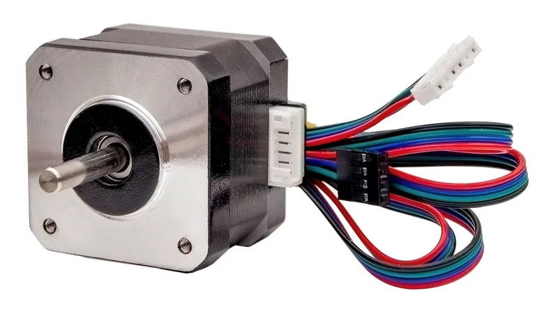
Stepper motor
Key Takeaways
A closed-loop stepper motor is a standard hybrid stepper fitted with position feedback (typically a rotary encoder), 5 driven by a controller that compares commanded position against actual position and corrects the difference; either after a move, continuously during the move, or via full sinusoidal (FOC) servo control, depending on which scheme the drive implements. 7
The failure mode it eliminates is step loss: (formally, "loss of synchronism" per NEMA ICS 16-2001) 1: when load torque exceeds the motor's pull-out torque at a given speed, the rotor falls out of synchronization with the stator field, and the open-loop drive never detects it.4
Because the drive can detect and correct positioning errors, you no longer need to oversize the motor for worst-case conditions. Open-loop steppers are commonly sized with a 30 to 50% torque margin below pull-out 10, which in practice often means selecting a motor 1.5 to 2 times larger than the load strictly requires.5
A closed-loop stepper system runs cooler, quieter, and with lower vibration than an open-loop one, because current is matched to actual load instead of being held at full rated current at all times. 5
"Closed loop" covers at least three different control schemes. Step-loss compensation (corrective steps issued when an error is detected), sensor-less/back-EMF stall detection, and full sinusoidal servo (FOC) control of a stepper. 7 Check which one a drive implements before you buy on the label.
Closed-loop steppers keep the stepper's torque advantage below roughly 1,000 rpm 12 and cost far less than a servo. They let you use the full torque-speed curve instead of holding a pull-out margin, but they do not move the curve itself. 6
Introduction
Stepper motors are attractive because they are simple. Feed a step and direction signal into a driver, and the rotor advances a fixed step angle per pulse with no feedback hardware, no tuning, and no encoder cable to route.
That simplicity has one serious failure mode. A stepper motor system is fundamentally an open-loop position control system, and as Texas Instruments notes in its application report on stall detection, the driver IC has no way of knowing whether the motor is actually turning or has stalled. 4 This is exactly the gap a closed-loop stepper motor is designed to close.
When the motor misses steps, everything downstream of that moment is wrong. A CNC machine cuts the rest of the part at an offset, a 3D printer produces a layer shift, and neither the controller nor the operator gets a warning until the damage is visible.
In this article, we'll cover what a closed-loop stepper motor is, why open-loop steppers fail silently, the different control schemes sold under the "closed loop" label, and how to decide when a closed-loop stepper motor is the right choice over a servo.
What is a Closed-Loop Stepper Motor?
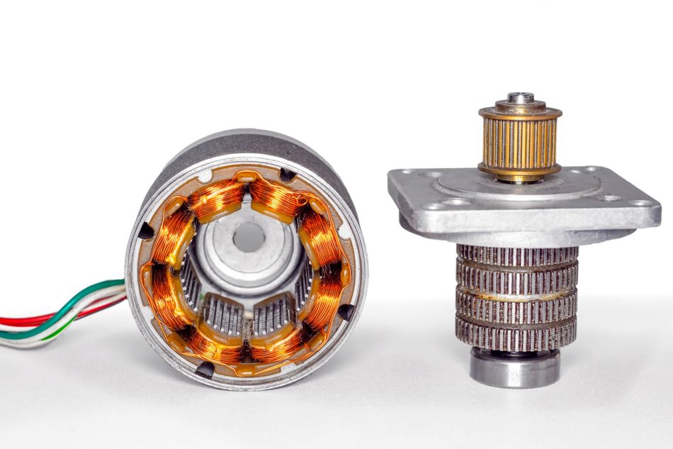
A closed-loop stepper motor is a standard hybrid stepper, with the same rotor, stator, and high pole count that gives steppers their low-speed torque 6, with a rotary encoder added on the rear shaft, paired with a drive that uses the encoder signal to close a position loop. 5
Vendors also market these as hybrid servo drives or servo stepper systems; Leadshine's HBS-series drives, for example, are branded exactly this way 11, because the control architecture borrows directly from servo practice.
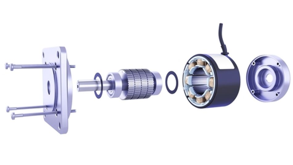
What's added is only the sensing and the drive logic. The motor itself doesn't change. A typical 1.8° step angle two-phase hybrid stepper still delivers 200 full steps per revolution, and a 0.9° step angle motor still delivers 400, identical to its open-loop counterpart. 13 Every difference in behavior comes from what the drive now knows, not from anything different inside the motor.
With the encoder in place, the drive continuously measures where the rotor actually is and adjusts current to match the torque the load actually needs, rather than supplying a fixed current sized for the worst case, as Performance Motion Devices frames it 5. That's the whole mechanical story. What's harder to pin down is how much correction a given drive actually performs with that information, and here the industry doesn't agree.
Nanotec draws a useful distinction between what it calls true closed-loop control and pseudo closed-loop control. A true closed-loop drive monitors rotor position continuously and corrects "load angle deviations within each full step." A pseudo closed-loop drive only checks whether steps are completed and patches the error after the fact. 10 That's a real functional gap, not a marketing nuance: one corrects errors as they happen, the other cleans up after them.
It's also a manufacturer drawing a line that happens to favor its own product, so it's worth noting the trade press reports the same divide independently. Some manufacturers restrict "true" closed-loop stepper control to systems using sinusoidal commutation with encoder feedback, arguing that steppers with an encoder but no field-oriented control can only detect a missed step, not correct for it mid-move. 7,8
You don't have to pick a side in that naming argument. You do have to read the datasheet closely enough to know which of these two behaviors a specific closed-loop stepper motor is actually giving you.
Recommended Reading: What is an Encoder: Understanding the Basics and Beyond
Why Open-Loop Stepper Motors Lose Steps
Understanding the fix requires understanding the failure. Step loss is not random, and it is not a manufacturing defect. It is a predictable consequence of the torque-speed physics of a stepper.
A stepper holds position by staying magnetically locked to the driver's commanded field. As load increases, the rotor lags slightly behind that field, an offset called the load angle, and torque grows with it, but only up to a limit. That limit is the motor's pull-out torque: the most it can produce at a given speed before the lock breaks entirely and the rotor slips out of sync. 4 Critically, pull-out torque falls as speed rises.
Machine Design's own torque curves show a motor producing about 0.71 N·m at zero speed, dropping to roughly 0.07 N·m at 1,000 rpm, a 90% loss. 12 So a stepper that holds a load comfortably at low speed can silently lose steps at higher speed on the same mechanical load.
Because an open-loop stepper has no way to detect this, the standard defense is brute force: oversize the motor, often by a factor of 2 or more, so the load never approaches the pull-out limit. That's the tax closing the loop lets you stop paying.
How Closed-Loop Stepper Control Works
The principle behind closed-loop control is straightforward, even if the engineering underneath it is not.
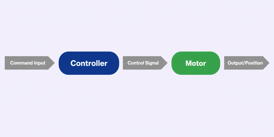
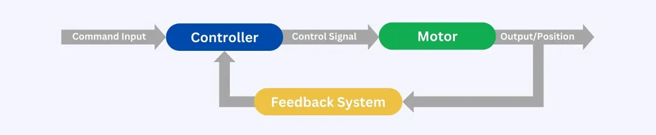
The controller specifies where the rotor should be. The drive energizes the motor phases to move it there. An encoder then reports where the rotor actually ended up, and the drive compares that measured position against the command it issued. Any difference between the two becomes a correction: the drive adjusts phase current and commutation angle until the error closes to zero.
What separates one closed-loop implementation from another is entirely a matter of how that correction is executed, how quickly, how continuously, and how intelligently the drive responds to the error it's given.
Position Feedback: Encoder Types and Resolution
Closed-loop stepper drives generally rely on one of two encoder categories: incremental or absolute.
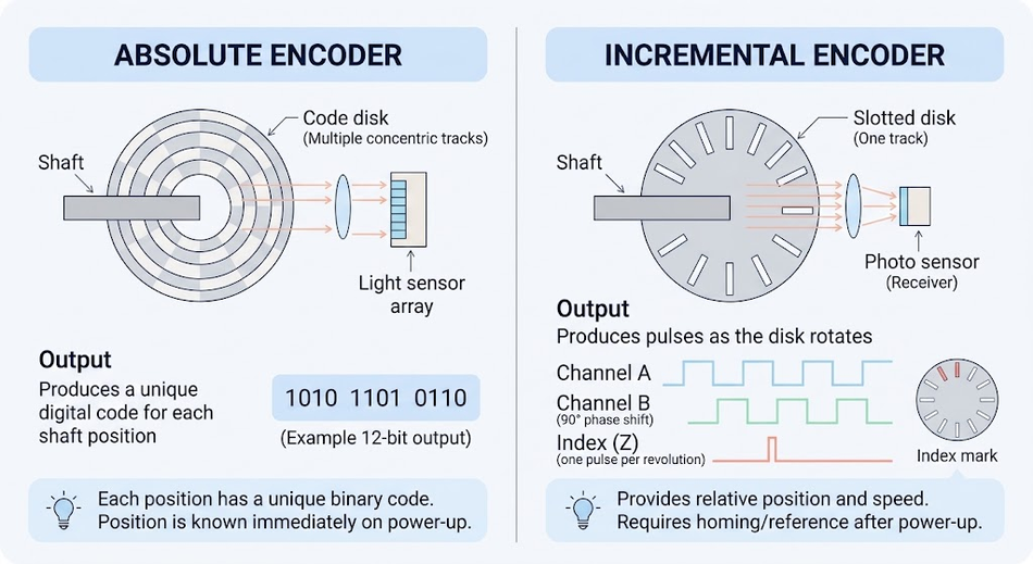
Incremental encoders are the most common and the cheapest, but they only know position relative to power-up, so the axis needs homing before every run. Absolute encoders report true shaft angle immediately on power-up, which matters on a vertical axis that must not drop or drift while the system is figuring out where it is. A third format, absolute-per-turn serial encoders (SSI or SPI), sits between the two: true angle within one revolution, but still needs a software counter to track full turns. The TMC4361A is one example of a drive that accepts all three formats (incremental ABN, absolute SSI, and absolute SPI) 3, illustrating how a single drive can support this whole range of sensor types.
Encoder resolution is quoted in lines, and drives typically apply quadrature decoding, multiplying the raw line count by four. Work the arithmetic through, because it determines the finest positioning error the system can even see:
Encoder | Counts per revolution (x4 quadrature) | Angular resolution | Counts per 1.8° full step |
1000 line encoder | 4,000 | 0.090° | 20 |
2500 line encoder | 10,000 | 0.036° | 50 |
A 1000 line encoder resolves each full step into 20 increments. That is enough to detect a developing load angle problem long before a full step is lost, which is what makes correction possible rather than merely diagnostic.
Commercial drives implement this exact scheme: the Leadshine HBS86H, for example, applies this same four-times multiplication to the raw encoder count and supports both 1000 and 2500 line encoders. 11
Recommended Reading: Absolute Encoder: Precision Positioning in the Digital Age
Optical, Magnetic, and Hall-Effect Sensing
The three sensing technologies work on different physical principles, and that difference drives where each one belongs.
Optical encoders read position through a slotted disc and a light source, the most precise method, but vulnerable to anything that blocks the light path. Magnetic encoders replace the light path with a shaft-mounted magnet and a field sensor, trading some precision for tolerance to dust, coolant, and vibration. Hall-effect sensors are a simpler, lower-cost variant of magnetic sensing, detecting a magnet's field angle directly rather than through a full encoder module.
A magnetic encoder tolerates dust, coolant mist, and vibration better than an optical one, which matters on a CNC router. The trade-off is accuracy, and it is larger than most selection guides admit.
Magnetic encoders in particular can show meaningful output variance even when correctly mounted, producing a position deviation that follows roughly a sine shape across a revolution. Analog Devices' own worked example, on a 200 full step motor at 256 microsteps per full step, shows a maximum deviation of 65 microsteps out of 51,200 per revolution before compensation. 3
Good drives correct this in firmware by adding a triangular offset function opposed to the deviation curve. 3 If you are specifying a magnetic encoder for a precision axis, confirm the drive offers that compensation rather than assuming the raw sensor accuracy.
Hall-effect sensors are the low-cost end of this family and have become viable for most step-loss work 9, though any absolute-per-revolution sensor is absolute only within a single turn; multi-turn tracking still needs a software accumulator with its own rollover to manage.
Encoder Placement
Mount the encoder on the motor shaft rather than at the load, absent a specific reason to do otherwise. Mounting elsewhere, across a belt or gearbox, introduces backlash and transmission compliance directly into the feedback loop, which simple load angle control cannot resolve; a full PID regulation scheme becomes necessary instead. 3
Load-side sensing does capture true final position, stretch and backlash included, but at the cost of a loop that is considerably harder to stabilize, a distinction frequently missed when feedback is retrofitted onto an existing belt-driven axis.
Load Angle and the 90° Limit
Load angle is the control variable that matters, and it has a hard physical meaning. The maximum usable load angle is 90°, the point of maximum torque, equivalent to one full step; drives typically allow this limit to be set anywhere from 0° to 180°. 3
The mechanism is direct. Phase currents produce a current vector the rotor should follow, the encoder samples where the rotor actually is, and the drive monitors the resulting load angle. As that angle approaches the limit, the drive shifts the current vector's direction to track the rotor's actual position, holding the load angle at or below the set limit so step loss doesn't occur. 3 That's the entire trick in one sentence: rather than pushing harder against an unknown, the commutation angle follows the rotor until the overload clears, then resumes normal positioning.
That is the whole trick stated in one sentence. Rather than pushing harder against an unknown, the commutation angle follows the rotor until the overload clears, then resumes normal positioning.
Pushing the limit past 90° doesn't buy more torque. Beyond that point, the drive enters a field-weakening mode that can raise achievable speed but at the cost of available force, and the total commutation angle has to stay under 180°, since going past that introduces unwanted reversals in motion direction. 3
Recommended Reading: Motor Speed Control: Methods Across Motor Types
Two Different Architectures
Here the vendor literature genuinely disagrees, and it is worth being precise because it changes what you are buying.
Nanotec describes its approach as sine commutation with an encoder using field-oriented control, where vector control holds the stator field perpendicular to the rotor and matches field strength to torque demand. 10 That is a classical FOC cascade: an inner current loop, a velocity loop, and a position loop.
Analog Devices explicitly rejects that description for its own part, framing its closed-loop motor control as distinct from field-oriented control. The TMC4361A keeps the ramp generator, the commutation angle control, and the current control independent of each other rather than nesting them in a PID cascade.3
Both prevent step loss. FOC generally gives smoother torque and is what the academic literature builds on; the load angle approach is simpler to configure and is common in step/direction drives. Treat "closed loop" on a datasheet as a category, not a specification, and check which one you are getting.
Holding a 90° electrical relationship is what extracts maximum torque per amp either way. PMD makes the point: with the current phase angle optimized against measured rotor position, the motor generates the greatest possible torque for a given current. Sinusoidal phase currents are also why a closed-loop stepper system delivers low vibration and near resonance-free operation compared to a coarsely micro-stepped open-loop drive.5
Three Levels of Closed-Loop Control
Not every product marketed as closed-loop does the same thing, and the difference matters when you are evaluating a datasheet. Design World's Danielle Collins sets out the three tiers used across the industry. 7
Approach | How it works | Trade-off |
Step-loss compensation | Drive runs in microstepping mode; encoder tracks the shaft, and the controller commands makeup steps when lost steps are detected | Simplest and most widely adopted, but it only corrects at the end of a move, not throughout it |
Load position control (closed-loop microstepping) | Shaft position is monitored continuously, and an error signal adjusts commands in real time across the whole move profile | The move profile is followed precisely; still commutates as a stepper |
Servo control (servo stepper) | The motor is driven as a two-phase brushless motor. A PID loop determines the torque needed to follow the profile, so the motor takes a torque command rather than pulses of current | Highest efficiency and no pull-out torque limitation, at the highest drive complexity |
That third tier is the one worth understanding, because it changes the torque story. Delivering only the current the profile actually requires means less wasted heat and longer motor life, largely eliminates the resonance problems that plague the other two methods, and lets the motor use its full rated torque without being boxed in by the pull-out limit. 7
Note the phase-geometry difference behind this: stepper motors have two phases offset by 90°, while brushless DC motors have three offset by 120°. 7
What the Research Measures
Vendor claims are one thing, instrumented results another. Ricci and Meacci at the University of Florence built an FPGA implementation of FOC torque control for hybrid steppers and published measured results 2, which is useful precisely because it lets you check vendor claims against independent, peer-reviewed data rather than taking a datasheet's word for it.
Their control loop updates the electrical position every 50 μs, which yields a load angle accuracy of about 1/100 rad at rotor speeds up to 750 rev/min 2. That 50 μs loop rate is worth noting for a practical reason: it also shows up in shipping commercial hardware, not just the lab. The Leadshine HBS86H specifies the same 50 μs position sampling interval 11, meaning a research result and a production drive have converged on the same loop-rate order independently.
Sensor less Stall Detection
Some drivers offer stall detection without an encoder, inferring rotor state from back-EMF. It is worth understanding why this is a different capability.
Back-EMF is proportional to speed and, per Texas Instruments, is phase-shifted 90° from coil current for an unloaded motor; as load approaches the motor's capability, back-EMF moves into phase with the current. TI's drivers monitor PWM off-time across current quadrants to build a torque count value, flagging a stall when it drops below a threshold. TI lists devices supporting this, covering 4.5 V to 65 V and up to 10 A. 4
This is genuinely useful for end-of-travel detection and jam diagnostics. But stall detection only tells you the motor stopped following; it doesn't report how many steps were lost, and it can't correct them. Only a real feedback system closes that gap.
Inside a Closed-Loop Stepper Motor Driver
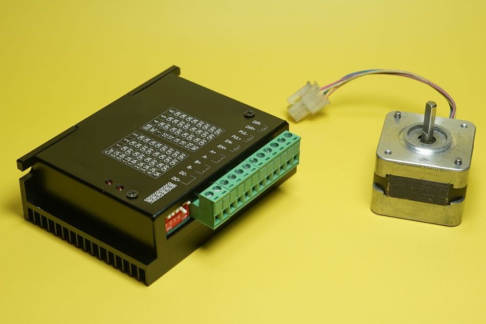
The motor barely changes when you close the loop. The drive changes completely. Where an open-loop chopper simply converts step pulses into winding current and trusts the rotor to keep up, a closed-loop drive continuously measures what the rotor is actually doing and corrects for the difference. That shift puts it much closer, in architecture and behavior, to a servo amplifier than to the chopper it replaces.
The Functional Blocks
Four elements do the work. A processor, usually a DSP, FPGA, or purpose-built motion ASIC, runs the control calculations. A power stage of MOSFETs switches the actual current into the motor windings. An encoder interface reads the rotor's position back in. And a current-sense circuit reports how much current is really flowing, as opposed to how much was commanded.3 Commands enter on one side, current leaves on the other, and the encoder feedback ties the two together so the drive is never working blind.
Nested Control Loops
A closed-loop stepper drive regulates on three levels at once, and the loops are nested deliberately.
The innermost current loop governs torque and must react the fastest. A velocity loop sits around it, and a position loop sits around that, each one setting the goal for the loop inside it. Production drives expose this structure directly: the Leadshine HBS86H, for example, gives separate proportional and integral gains for its current, speed, and position loops, plus a damping term for running near a resonance 11. Because position error is sampled at very high rates, on the order of tens of microseconds 11,2, the drive catches a developing deviation long before it grows into a lost step.
One consequence of this architecture is efficiency. Rather than holding full rated current at all times the way an open-loop drive must, a closed-loop drive separates the current needed to hold position from the extra current needed to correct an error, and draws the second only when the load actually demands it. Less wasted current means less heat.
Fault Limits and Settling
Feedback is only useful if the drive knows when to stop trusting it. Every closed-loop drive defines a position-error limit, a maximum following error beyond which it stops correcting and raises a fault instead of driving a jammed axis indefinitely.11 That limit is a genuine tuning decision: set it too tight and normal acceleration trips false faults; set it too loose and a real obstruction goes unreported.
Alongside it sits a dead band, a small tolerance inside which the drive intentionally does nothing, kept just above the encoder's own resolution so the loop doesn't chase sensor noise as if it were real motion. The same discipline applies to declaring a move complete: a well-designed drive withholds its "in-position" signal until the measured position has actually settled within tolerance, not the moment its internal profile ends, so the controller learns the axis truly arrived rather than that the pulse train simply stopped.
Why the Encoder Cable Matters
The encoder cable deserves more attention than it usually gets, because it is a common source of intermittent, hard-to-trace faults. The feedback signal runs physically close to motor leads carrying sharply switched current, and that proximity invites electrical noise. Differential signaling, proper shielding, and grounding the shield at a single end all exist to protect that signal. 11 The stakes are specific: a noise-corrupted encoder reading doesn't look like a fault to the drive; it looks like real position error, and the drive will faithfully correct against data that was never true.
Networked Drives
Step-and-direction wiring is adequate for a single controller driving a single axis, but industrial systems increasingly expect drives on a fieldbus. EtherCAT and CANopen interfaces do more than collapse per-axis pulse wiring onto one network; they make the drive's own knowledge readable upstream. Actual position, following error, and fault state become variables the controller can act on directly, instead of a status LED someone has to be standing in front of to read.
What the Added Complexity Buys
None of this exists in a basic chopper, which has no loop to tune, no threshold to set, and no feedback line to protect, and that simplicity is exactly why open-loop drives remain cheaper and quicker to commission. Everything a closed-loop drive adds: the nested loops, the fault limits, the wiring discipline, buys one thing the chopper can never offer: confirmation that the commanded move actually happened.
Open-Loop vs Closed-Loop Stepper Motor
Characteristic | Open-loop stepper motor | Closed-loop stepper motor |
Position feedback | None | Incremental encoder, typically 1,000 to 2,500 lines 13 |
Step loss | Undetected and uncorrected | Detected and corrected in real time |
Sizing margin | Oversized by a factor of 2 or more; up to 50% safety margin. 5,10 | Sized close to actual load |
Current at light load | Full rated current regardless of load | Current matched to load demand 5 |
Heat | Excess power dissipated as heat | Cooler operation, longer service life 5 |
Vibration and noise | Higher, resonance-prone | Low vibration, practically resonance-free 5 |
Overload behavior | Stalls and loses position silently | No stoppage on overload; faults when error limit is exceeded 11 |
Cost and wiring | Lowest | Added encoder, encoder cable, and drive cost |
Closed-Loop Stepper vs Servo
This is the decision most engineers actually face, and the honest answer is that closing the loop does not turn a stepper into a servo. It removes the stepper's worst failure mode while leaving its physics intact.
The structural difference is pole count. PMD notes that stepper motors have high pole counts of 100 or more, while servo motors typically run 4 to 8 poles. High pole count is exactly why a stepper produces large holding torque at low speed and why its torque collapses at high speed. 6
Criterion | Closed-loop stepper | Servo |
Pole count | 100 or more | Typically 4 to 8 6 |
Torque at low speed | Excellent, high holding torque | Good, often needs a gearbox 6 |
Torque above ~1,200 rpm | Falls off steeply | Roughly constant into the thousands of rpm 12 |
Practical resolution under load | Roughly 4,000 to 10,000 counts per revolution 3,11 | Higher, encoder-dependent |
Maximum practical torque | Rarely above 7 to 14 N·m (1,000 to 2,000 oz-in) 13 | Up to roughly 339 N·m (250 ft-lb) |
Largest common frame | NEMA 34 12,13 | Commonly specified by metric flange size, up to roughly 220 mm |
Magnets | Conventional | Typically rare-earth |
Commissioning | Often simpler on stiff, predictable mechanics | Requires tuning, more capable when tuned |
Cost | Up to an order of magnitude cheaper | Highest 6 |
Choose a closed-loop stepper when your axis spends its life below about 1,000 rpm, the load is predictable, and you want high precision positioning without servo cost or tuning effort. Choose a servo when you need sustained torque at high speed, aggressive acceleration, or the tightest achievable resolution.
PMD offers a sensible caution on the money: motor cost alone rarely tells the full story 6. Count the encoder, the drive, the cabling, and the commissioning hours.
Recommended Reading: Stepper vs Servo Motors: Mastering Motor Selection for Precision Engineering
Sizing: NEMA 17, NEMA 23, and NEMA 34
NEMA frame numbers describe the mounting face, not the torque. The number is the faceplate width in tenths of an inch, so a NEMA 23 has a face close to 2.3 inches 1. It says nothing about winding, torque, or length.
The governing document is NEMA ICS 16-2001, Motion/Position Control Motors, Controls and Feedback Devices, a standard that defines the scope of motion-control components covered, including servo and stepping motors, their feedback devices such as encoders and resolvers, and the controls that drive them within a system built for precise positioning, speed, or torque control. 1 It standardizes the mechanical interface, which is why any vendor's NEMA 23 bolts to your machine. It does not standardize what comes out of the shaft.
Frame | Nominal face | Actual body (typical) | Mounting hole pattern | Typical shaft | Where a closed loop version earns its cost |
NEMA 17 | 1.7 in (43.2 mm) | 42 x 42 mm, 21 to 48 mm long | 31.0 mm square, M3 | 5 mm | 3D printers and desktop robotics where a layer shift ruins a long print |
NEMA 23 | 2.3 in (58.4 mm) | 57 x 57 mm, 56 mm and up | 47.1 mm square, 5 mm through-holes | 6.35 mm (1/4 in) | Benchtop CNC machines and CNC router axes cutting hardwood or aluminum |
NEMA 34 | 3.4 in (86.4 mm) | 86 x 86 mm | Larger bolt circle, heavier flange | Commonly 12.7 to 14 mm | Gantry routers and industrial automation axes carrying real cutting loads |
Real holding torque figures make the point that frame size is a weak proxy. Across one manufacturer's standard 1.8° catalog, NEMA 17 motors run from 16 Ncm on a short 42 x 42 x 21.5 mm extruder motor, to 22 Ncm at 34 mm long, to 59 Ncm at 48 mm long. A NEMA 23 at 57 x 57 x 56 mm gives 1.26 N·m. Body length, not frame number, is doing most of the work.
A NEMA 23 closed-loop stepper motor is the most common choice in hobby and light industrial CNC. NEMA 17 closed-loop kits target 3D printing, where the failure being designed out is a layer shift halfway through a multi-hour print.
One practical note on buying: vendor listings use their own spelling, and a NEMA 23 closed-loop stepper motor is usually sold as a matched kit rather than a bare motor. 13 Check what is actually in the box, because a NEMA 23 closed-loop stepper motor advertised at a low price often ships without the drive, and the drive is where the closed-loop capability lives.
Size on the mechanics, not the frame number. Work out the worst-case torque at the highest speed the axis will actually run, then check that figure against the motor's pull-out torque curve at that speed rather than against its holding torque. 4
The payoff of closing the loop is that you can size to real load plus a modest margin instead of doubling up. In many retrofits, the closed-loop motor is the same frame size as the open-loop one it replaces, and the gain shows up as reliability rather than raw torque.
Applications
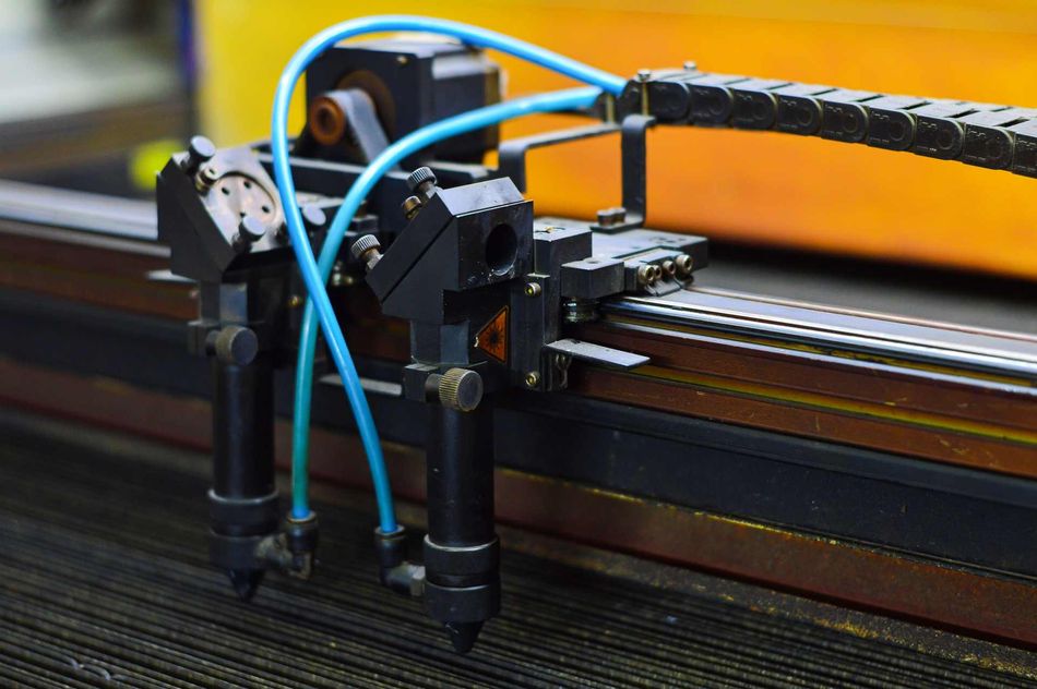
CNC machines and CNC routers. These are the strongest case. Cutting forces vary with material, depth, and tool condition, so worst-case torque is hard to predict, and step loss scraps the workpiece. Closed-loop NEMA 23 and NEMA 34 systems are standard on router gantries.
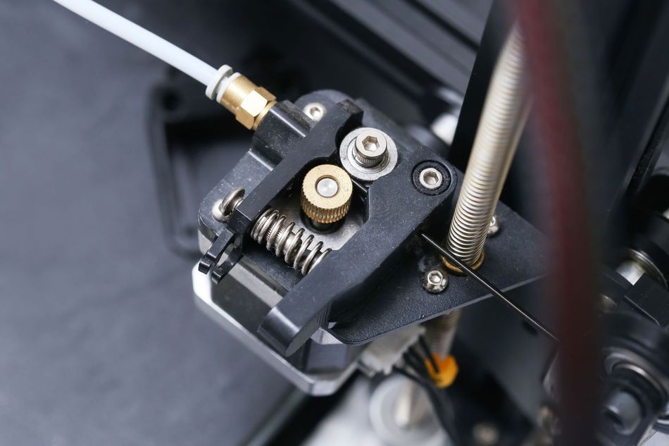
3D printing. Layer shifts from missed steps on X or Y are the classic stepper failure in 3D printers. Closed-loop NEMA 17 motors detect a belt skip or a nozzle collision instead of printing the remaining hours at an offset.
Robotics. Pick-and-place arms and lab automation benefit from position feedback for both accuracy and safety. Knowing that an axis stalled, rather than assuming it arrived, changes what the machine can safely do next.
Industrial automation. Conveyors, indexers, dispensing heads, and packaging machinery use closed-loop steppers where servo performance is unnecessary but silent position loss is unacceptable. Fieldbus-connected drives report following error straight to the PLC.
Recommended Reading: What Is a CNC Router? An Introduction for Engineers
Common Mistakes and Troubleshooting
Assuming closed-loop means you can undersize. It means you can stop oversizing by 2x, not that you can run at the pull-out limit.5 Keep a real margin against the torque-speed curve.
Setting the position error limit by trial and error. Tune acceleration first. Most nuisance following-error faults are an acceleration profile the mechanics cannot deliver, not a bad limit value.11
Running the encoder cable in the motor power loom. This is the leading cause of intermittent, hard-to-reproduce positioning errors. Separate the runs and use shielded twisted pairs.11
Expecting high-speed torque. Closing the loop does not move the motor's torque-speed curve. 6 It does let you use more of it, because a servo-controlled stepper can run at full rated torque instead of holding back a pull-out margin. 7 What it cannot do is create torque at 2,000 rpm that the motor never had. If your rapids need that, the answer is a servo or a different gear ratio.
Ignoring rated current settings. Current parameters set static and dynamic torque separately on many drives. Leaving them at defaults for a different motor gives up much of the efficiency and thermal benefit. 11
Treating stall detection as position feedback. Sensorless stall detection flags that something went wrong. As EDN puts it, stall detection can confirm the motor is moving but cannot report how many steps were actually lost. 9
Mounting the encoder on the load without retuning. If the encoder is not on the motor shaft, belt stretch and backlash sit inside your feedback loop. That configuration requires proper PID regulation, not the default load angle settings.3
Treating step-loss compensation as a license to skip the engineering. It is insurance, not a first line of defense. Size and test the axis so it does not miss steps in the first place, because when a machine does lose steps, it usually loses several at once rather than one at a time.7
Set the correction deadband below one encoder count. Make the tolerance slightly wider than a single encoder increment. Narrower than that and the loop reacts to encoder quantization noise instead of real position error.3
Conclusion
A closed-loop stepper motor is the pragmatic middle of the motion control market. You keep the stepper's low cost, high holding torque, and straightforward step-and-direction interface, and you delete the failure mode that makes open-loop steppers unsuitable for anything where a lost step is expensive.
The engineering payoff is broader than just catching missed steps. Matching current to actual load makes the system run cooler and quieter, field-oriented control gives smoother motion, and feedback lets you size the motor to the real load rather than to a worst case you cannot measure.
What it does not do is move the torque-speed curve. It lets you use more of the curve, because you can run at rated torque rather than reserving a pull-out margin, but the falloff at speed is a property of the motor and stays where it is.
If your application lives below about 1,000 rpm, a closed-loop stepper is very likely the right answer. Above that, the physics still favors a servo.
Frequently Asked Questions
Is a closed-loop stepper motor the same as a servo?
No. It uses servo-style feedback and often field-oriented control, but it remains a high-pole-count stepper with roughly 100 or more poles compared to a servo's 4 to 8. 6 It keeps the stepper's low-speed torque advantage and its high-speed torque falloff. 12
Can I convert my existing open-loop stepper to closed loop?
Not as a simple upgrade. You typically replace the motor, drive, and encoder together, since the encoder must be mechanically mounted and electrically matched to the drive.3,11 Retrofits are normally sold as a matched motor, drive, and encoder cable kit in the same NEMA frame.13
What encoder resolution do I need?
A 1000-line encoder giving 4,000 counts per revolution resolves a 1.8° full step into 20 increments, which is sufficient for most CNC and 3D printing work.3,11 Step up to a 2500-line encoder when you need finer error detection or smoother field-oriented commutation.11
Should I use an incremental or absolute encoder?
Incremental is cheaper and standard, but it only knows position relative to power-up, so the axis must home on every start. Choose absolute for a vertical axis or anything that must know where it is immediately after a power cycle. Note that most absolute encoders are absolute within one revolution only, so multi-turn position still needs a software accumulator.9
Does the encoder go on the motor or the load?
On the motor shaft by default. Sensing at the load puts belt stretch, backlash, and coupling compliance inside your feedback loop, which makes it harder to stabilize and requires proper PID tuning rather than default load angle settings.3 Sense at the load only when you specifically need to correct for transmission error.
Do closed-loop steppers still lose steps?
No, not silently. A true closed-loop drive corrects load angle deviations continuously, so position is maintained under normal operation. If the load exceeds what the motor can deliver, the drive accumulates following error and raises a position error fault instead of losing position unnoticed.11
Why does my drive fault during fast moves but not slow ones?
Pull-out torque falls as speed rises, so a load that is comfortable at low speed can exceed the motor's capability during rapids.4,12 Reduce acceleration or top speed, or move up a frame size.
Is a closed-loop stepper worth it for a 3D printer?
Yes, for long or unattended prints. Detecting a layer shift instead of completing hours of offset printing usually justifies the cost, especially for expensive material or a printer running without supervision.
What is the difference between microstepping and closed-loop control?
Microstepping subdivides each full step to smooth motion and increase command resolution, but it is still open-loop: the drive assumes the rotor followed. Closed-loop control verifies that it did. The two are complementary and most closed-loop drives microstep as well.7
References
[1] National Electrical Manufacturers Association, "ICS 16-2001, Motion/Position Control Motors, Controls and Feedback Devices," Oct. 2002. [Online]. Available: https://www.nema.org/standards/view/motion-position-control-motors-controls-and-feedback-devices
[2] S. Ricci and V. Meacci, "Simple Torque Control Method for Hybrid Stepper Motors Implemented in FPGA," Electronics, vol. 7, no. 10, p. 242, 2018. [Online]. Available: https://doi.org/10.3390/electronics7100242
[3] Analog Devices, "AN-032: TMC4361A Closed-loop Motor Control for Stepper Motor Drivers." [Online]. Available: https://www.analog.com/en/resources/app-notes/an-032.html
[4] D. Mitra and M. Afshar, "Sensorless Stall Detection for Stepper Motors," Texas Instruments, SLVAEI3A, Jan. 2020, rev. Feb. 2026. [Online]. Available: https://www.ti.com/lit/an/slvaei3a/slvaei3a.pdf
[5] Performance Motion Devices, "Keep Your Step Motor Position with A Closed Loop Motion Control System." [Online]. Available: https://www.pmdcorp.com/resources/type/articles/keep-your-step-motor-position-with-a-closed-loop-motion-control-system
[6] Performance Motion Devices, "Closed Loop Stepper vs Servo: How to Choose the Right Motor Control Approach." [Online]. Available: https://www.pmdcorp.com/quickbytes/closed-loop-stepper-vs-servo-how-to-choose-the-right-motor-control-approach
[7] D. Collins, "How does closed-loop stepper control work (and why not just use a servo)?," Design World LinearMotionTips. [Online]. Available: https://www.linearmotiontips.com/how-does-closed-loop-stepper-control-work/
[8] MotionControlTips, "FAQ: What is closed-loop stepper motor control with step-loss compensation?" [Online]. Available: https://www.motioncontroltips.com/faq-closed-loop-stepper-motor-control-step-loss-compensation/
[9] EDN, "No more missed steps: Unlocking precision with closed-loop stepper control." [Online]. Available: https://www.edn.com/no-more-missed-steps-unlocking-precision-with-closed-loop-stepper-control/
[10] Nanotec, "Closed-Loop Technology." [Online]. Available: https://www.nanotec.com/us/en/knowledge-base-article/closed-loop-technology
[11] Leadshine, "HBS86H Hybrid Stepper Servo Drive Manual." [Online]. Available: https://hardware-cnc.nl/images/PDF/ACT/HBS86H_English_Manuel.pdf
[12] B. Lackey, "Stepper and Servo Motor Tradeoffs," Machine Design, Feb. 8, 2023 (updated Jan. 24, 2024). [Online]. Available: https://www.machinedesign.com/automation-iiot/article/21836868/stepper-and-servo-motor-tradeoffs
[13] StepperOnline, "NEMA Stepper Motor Sizes." [Online]. Available: https://www.omc-stepperonline.com/nema-stepper-motor-sizes
[14] RepRap, "NEMA Motor." [Online]. Available: https://reprap.org/wiki/NEMA_Motor
in this article
1. Key Takeaways2. Introduction3. What is a Closed-Loop Stepper Motor?4. Why Open-Loop Stepper Motors Lose Steps5. How Closed-Loop Stepper Control Works6. Inside a Closed-Loop Stepper Motor Driver7. Open-Loop vs Closed-Loop Stepper Motor8. Closed-Loop Stepper vs Servo9. Sizing: NEMA 17, NEMA 23, and NEMA 3410. Applications11. Common Mistakes and Troubleshooting12. Conclusion13. Frequently Asked Questions14. References