How to 3D Print: A Quick-Start Guide for Engineers
A comprehensive guide that summarizes how to 3D print an object, including digital design, slicing, printing, and post-processing.

29 Jul, 2025. 15 minutes read
Additive manufacturing (AM), commonly known as 3D printing, has transformed product development and manufacturing by enabling the direct fabrication of complex three‑dimensional objects from digital models. Unlike subtractive manufacturing, which cuts away material from a block, AM builds parts layer by layer, allowing complex geometries, internal lattices, and integrated assemblies that would be impossible or costly to manufacture with traditional methods.
Although 3D printing is less of a buzzword than it was a decade ago, demand for 3D printing has actually surged in recent years. According to the 2025 edition of the Wohlers Report, a reliable and internationally recognized market study on 3D printing, the global additive manufacturing industry grew by 9.1% overall in 2025 to $21.9 billion, thanks mostly to the development of the AM industry in Asia and China in particular.[1]
So how do you actually get started with additive manufacturing technology to make parts and prototypes? This article provides engineers and engineering students with an in‑depth guide on how to 3D print. It first explains the major additive manufacturing technologies and materials before diving into design considerations, hardware components, software, and workflow.
How to 3D Print: Step By Step
3D printing, or additive manufacturing, is a multi-stage process that transforms digital designs into physical objects by adding material layer by layer. Whether you're prototyping a functional part or printing a custom model, the process involves both digital preparation and physical execution. While specific workflows vary slightly by technology (e.g., FDM, SLA, SLS), most 3D printing jobs follow a similar structure from design to inspection.
CAD Modeling
Everything begins with a 3D digital model, created in CAD (Computer-Aided Design) or 3D design software such as SolidWorks, Fusion 360, Siemens NX, Rhino, or free tools like TinkerCAD or FreeCAD. The design may follow parametric rules or organic modeling techniques, depending on the application. At this stage, engineers should follow DfAM (Design for Additive Manufacturing) principles—such as avoiding overhangs beyond 45°, adding fillets to reduce stress, planning support placement, and accounting for layer orientation and anisotropic strength.
Export and File Formats
Once the model is finalized, it is exported to a printable file format. STL (Standard Tessellation Language) is the most common and uses triangular facets to represent geometry, though it lacks metadata such as scale, color, or material.[2] Alternatives like AMF (Additive Manufacturing File Format) and 3MF (3D Manufacturing Format) are gaining popularity, as they preserve units, textures, multi-material data, and even lattice structures. These files are then transferred to slicing software.
Slicing
Slicing converts the 3D model into a series of horizontal layers and generates a set of machine instructions (usually G-code) tailored to the selected printer and material. The slicer calculates movement paths, extrusion volumes, print speeds, and temperature settings. Popular slicers include Ultimaker Cura, PrusaSlicer, Simplify3D, Slic3r, and IdeaMaker. Key settings include layer height, shell thickness, infill pattern and density, support generation, bed adhesion strategies, and retraction settings to prevent stringing.
Recommended reading: What is Slicing in 3D Printing? A Guide for Engineers
Printer Setup and Calibration
Before printing, the machine must be prepared. This includes leveling the build plate (manually or via auto-leveling), setting the correct nozzle height (Z-offset), loading filament or resin, and preheating the print bed and hot end. Calibration prints such as temperature towers, flow rate tests, and retraction cubes help fine-tune material-specific parameters. Resin printers may also require screen calibration and exposure tuning.
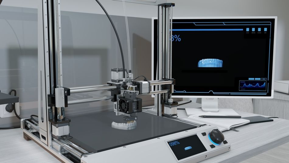
Printing
Once everything is set, the print begins. The printer executes the G-code to either extrude, cure, sinter, or bind material. It’s critical to observe the first few layers to ensure proper adhesion to the bed. For long-duration prints, monitoring is advised—many printers support webcam integration or remote monitoring. In resin printing, peel forces and suction between the cured layer and the vat film must be managed carefully, often using tilt mechanisms.
Post-Processing
After printing, parts must be cleaned and finished. FDM prints often require support removal, sanding, or vapor smoothing (especially with ABS). SLA prints need isopropyl alcohol washes and UV curing.[3] Powder-based prints (SLS, MJF) may require depowdering and surface finishing, while metal parts from DMLS or Binder Jetting might undergo sintering, heat treatment, or surface machining. Common post-processing steps include annealing, dyeing, tumbling, infiltration (e.g., with epoxy), or threading tapped holes.
Recommended reading: The Complete Guide to 3D Printing Post Processing
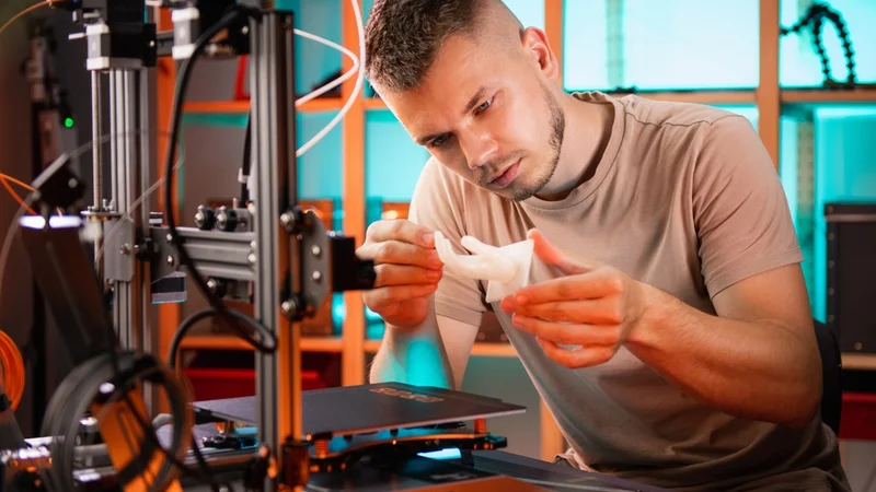
Inspection and Testing
Final parts should be evaluated for dimensional accuracy and material performance. This may involve using calipers, micrometers, or coordinate measuring machines (CMMs). Mechanical testing (e.g., tensile strength or hardness) ensures that performance targets are met. Surface quality may be assessed visually or with profilometers, while critical internal features—especially in aerospace or medical applications—can be examined using CT scanning or X-ray inspection to check for porosity or delamination.
How to 3D Print Without a 3D Printer
You don’t need to own a 3D printer to create 3D printed parts. Online 3D printing service bureaus offer an accessible alternative, allowing anyone to upload a 3D model and have it printed and shipped professionally. Services like Shapeways, Xometry, Hubs, and Sculpteo let users choose materials, technologies, and finishes, then generate instant quotes based on geometry and volume. After placing an order, parts are manufactured using the provider’s equipment and mailed to the customer.
To use a service bureau, start with a digital 3D model in STL, STEP, or OBJ format. Most platforms offer automated tools to check and repair common mesh issues. You then select the print technology (e.g. SLS, SLA, MJF, FDM, or DMLS), material (plastics, resins, or metals), and tolerances. Some platforms also offer design-for-manufacturing checks or manual review services to reduce the risk of printing errors.
Pros of Using a 3D Printing Service:
Access to Industrial-Grade Technologies: You can use high-end equipment like SLS (Selective Laser Sintering) or DMLS (Direct Metal Laser Sintering), which are prohibitively expensive for personal ownership.
Wider Material Selection: Industrial bureaus offer a broader range of materials including titanium, carbon-filled nylons, PEEK, and flexible TPU, many of which are not usable on consumer machines.
No Maintenance or Setup: You don’t need to worry about calibrating a printer, fixing jams, or dealing with failed prints.
Scalability: Ideal for low-volume production, prototyping, or on-demand spare parts without upfront capital investment.
Cons Compared to Owning a 3D Printer:
Longer Lead Times: Including production and shipping, lead times often span several days, whereas home printers can produce parts in hours.
Higher Cost per Print: For frequent or iterative prototyping, the cost can add up quickly versus owning a reliable desktop printer.
Limited Iteration Speed: Modifying and reprinting a part takes longer, which can hinder agile development or rapid prototyping.
Less Immediate Control: You can’t tweak settings mid-print or physically inspect the build in progress.
Using a service bureau is ideal for those who need high-quality parts occasionally or access to materials and processes beyond hobbyist machines. For engineers, artists, or product developers without in-house equipment, it offers a powerful way to bring ideas to life—without the overhead of ownership.
How to 3D Print Without CAD
Not all 3D printing projects require original CAD work. Engineers, technicians, and technical users can often find high-quality, pre-designed STL files online, saving time during early prototyping, benchmarking, or proof-of-concept phases. These ready-to-print models eliminate the need for CAD modeling and are ideal for standardized parts, fixtures, brackets, enclosures, or demonstration geometries.
Several platforms host extensive libraries of printable files. Thingiverse, Printables (by Prusa), and Cults 3D offer community-sourced designs, many of which are parametric or optimized for common FDM printers. MyMiniFactory is useful for detailed visual parts, while CGTrader, GrabCAD, and TurboSquid also offer 3D models, though not specifically for 3D printing.
Once downloaded, the STL file is imported into a slicer (such as Cura or PrusaSlicer), where settings are adjusted for the specific printer and material. Engineers can quickly validate printability, estimate build time, and simulate support generation before sending G-code to the printer. Of course, these downloaded files can also be sent to a 3D printing service bureau for remote printing.
Making a 3D Printable Model With 3D Scanning
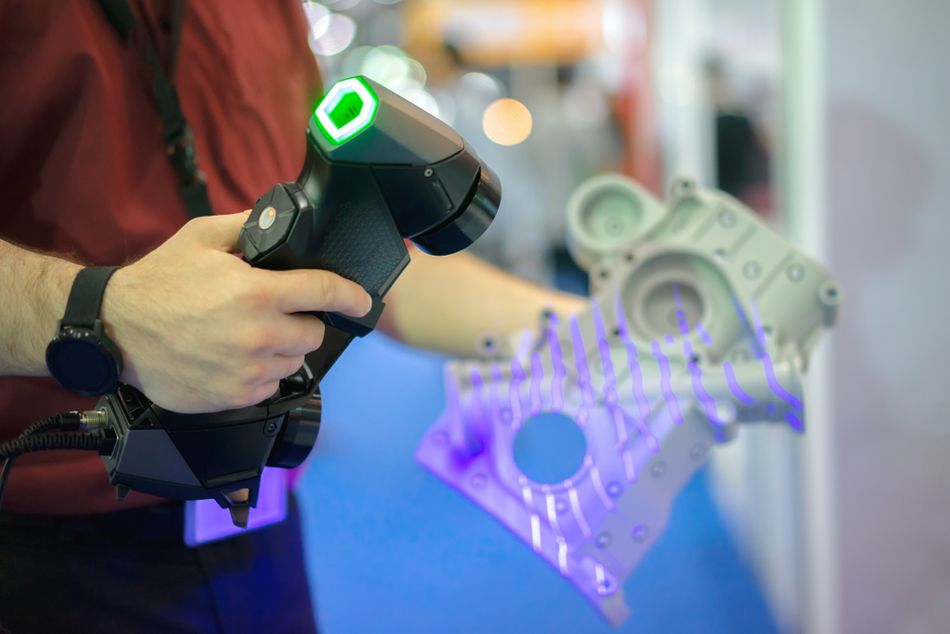
3D scanning allows engineers and designers to create printable models by capturing the shape of real-world objects. Instead of designing from scratch in CAD, a 3D scanner collects millions of data points from an object’s surface and generates a 3D mesh—usually in STL or OBJ format—ready for post-processing and printing.
Common scanning technologies include structured light, laser triangulation, and photogrammetry.[4] Handheld scanners like those from Artec or Revopoint are suitable for medium-detail parts, while metrology-grade systems offer high accuracy for engineering applications. After scanning, the raw mesh typically requires cleanup using software like MeshLab, Artec Studio, or Geomagic. This may involve hole filling, noise reduction, mesh decimation, and watertight sealing to ensure the model is printable.
Scanned models are especially useful for reverse engineering, reproducing legacy parts, or digitizing organic shapes that are difficult to model in CAD. However, they often lack parametric features or design intent, so editing can be limited. For functional parts, engineers may import the scan into CAD as a reference to create a new, dimensionally controlled model. Once prepared, the 3D file can be sliced like any other file and sent to the printer, enabling physical replication of real-world geometry with minimal manual modeling.
Additive Manufacturing Technologies
While extrusion-style 3D printing is the most common and widely accessible printing process, there are actually seven different technology categories. Some of these technologies are also fairly accessible for engineers of all levels, while others are restricted to industrial use.
Material Extrusion (FDM/FFF)
Fused deposition modeling (FDM), also called fused filament fabrication (FFF), is the most prevalent consumer and prototyping technology. A thermoplastic filament is drawn into a heated nozzle, melted and extruded onto a build platform in thin strands. The nozzle moves in the X–Y plane while the build platform moves in the Z direction, depositing successive layers to form the part. Typical layer heights range from 0.05 mm to 0.4 mm. Materials include commodity polymers such as ABS, PLA and PETG, engineering plastics like PEI (ULTEM) and PEEK, and specialty filaments filled with carbon fibre or metal powder.
Advantages:
Low cost and accessibility. Desktop FDM printers are inexpensive, making them ideal for prototyping and education.
Material versatility. A broad range of thermoplastics, including flexible and composite filaments, are available.
Ease of use and maintenance. FDM systems are relatively simple to operate and maintain.
Limitations:
Lower resolution and accuracy. Layer thickness and nozzle diameter limit detail. Typical dimensional accuracy is ±0.2 mm for desktop systems.
Anisotropic mechanical properties. Bonding between layers is weaker than within layers, so parts may fail along layer lines. Orienting parts to align layers with load directions is important.
Support structures and warping. Overhangs above ~50° often require support material, and large flat areas can warp due to uneven cooling.
Design considerations for FDM
Minimum feature size: Should exceed 1.2–1.5× nozzle diameter (commonly 0.4 mm), meaning walls should be ≥ 0.6 mm thick.
Orientation: Orient parts so that critical features have layers perpendicular to load; vertical features oriented along Z are weaker.
Overhangs and bridges: Overhang angles > 50° need support; bridging up to 10 mm may be printed without support if cooling is adequate.Infill density: Infill patterns (rectilinear, honeycomb, gyroid) and densities (10–100 %) control weight and strength. Higher infill increases stiffness but lengthens print time.
Warp mitigation: Enclose the build chamber and maintain uniform temperature. Use brim or raft, chamfer edges and add fillets to distribute stress.
Vat Photopolymerization (SLA/DLP)
Vat photopolymerization encompasses stereolithography (SLA) and digital light processing (DLP). In SLA, a UV laser selectively cures a layer of liquid photopolymer resin. After curing each layer, the build platform lowers to submerge the cured layer in resin and the next layer is scanned. Layer thickness ranges from 0.025 mm to 0.5 mm, enabling high resolution and smooth surfaces. DLP projects an entire image onto the resin using a digital projector, curing each layer in one flash.
Advantages:
High accuracy and surface finish. Layer thickness as small as 25 µm allows fine details and smooth surfaces.
Complex geometries. UV light can cure intricate internal channels and cavities.
Limitations:
Material constraints. Limited to photopolymer resins; mechanical properties may be inferior to thermoplastics.
Post‑processing. Parts require rinsing, removal of supports and secondary UV curing to reach final properties.
Resin handling. Uncured resin is toxic and requires careful handling and disposal.
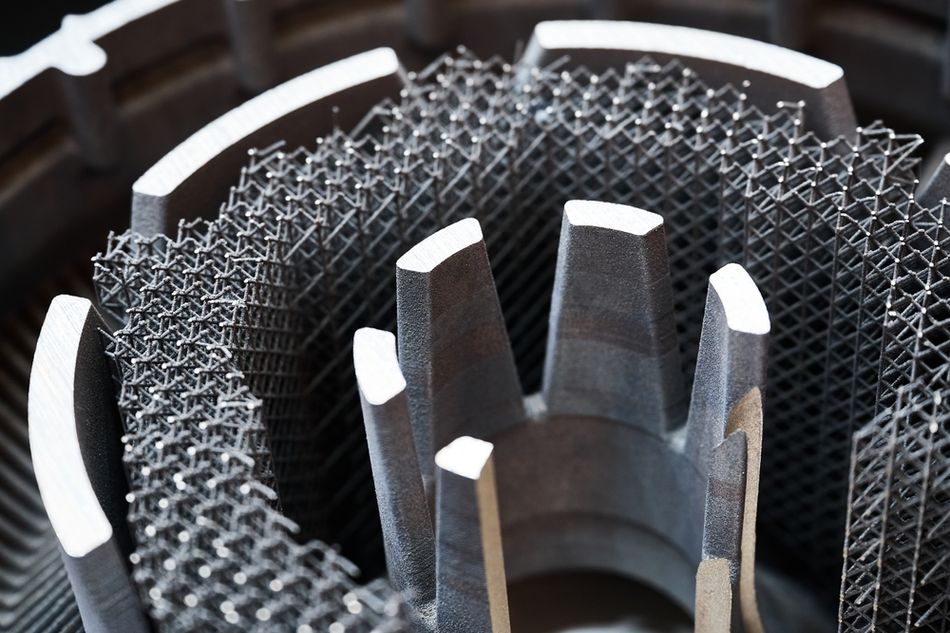
Powder Bed Fusion (PBF)
Powder‑bed fusion processes spread a thin layer of powder across a build platform and selectively fuse it using a high‑energy source. Variants include selective laser sintering (SLS), selective laser melting (SLM), direct metal laser sintering (DMLS) and electron beam melting (EBM). Layer thickness is typically ~0.1 mm.
SLS uses a CO₂ laser to heat polymer powder (usually nylon) until it sinters. Unsintered powder supports overhangs, eliminating the need for additional support structures.
SLM/DMLS fully melt metal powders (aluminum, titanium, steel). They require an inert gas environment and produce dense parts with mechanical properties similar to wrought metals.
EBM employs an electron beam in a vacuum, melting metal powder at high speed. It yields parts with low residual stress but requires vacuum chambers and conductive materials.
Advantages:
No support structures required. Surrounding powder supports the part, enabling complex overhangs.
Good mechanical properties. Fully melted metals have high strength and density.
Industrial scalability. PBF is widely used for aerospace, medical implants and tooling.
Limitations:
High equipment cost. Industrial lasers or electron beams and inert atmospheres are expensive.
Surface roughness. Parts often require post‑processing (machining, polishing) to achieve desired surface finish.
Powder safety. Fine metal powders are hazardous and must be handled with care.
Material Jetting
Material jetting is similar to a 2D inkjet printer but deposits droplets of photopolymer or wax onto a build platform. As droplets land, they are cured by UV light. Drop‑on‑demand and continuous inkjet methods can be used. The process can deposit multiple materials in the same layer, allowing colour and material gradients.
Advantages:
High precision and surface quality. Accuracy similar to SLA.
Multi‑material and colour printing. Multiple print heads enable material blends and colour gradients.
Limitations:
Limited materials. Photopolymer droplets are rigid or wax‑like; mechanical properties are limited.
Requires support material. Jetting often needs soluble supports, which increases material consumption.
Binder Jetting
Binder jetting uses two materials: a powder bed and a liquid binder ejected by an inkjet print head. The binder selectively binds powder particles, layer by layer. After printing, the part is cured and often sintered or infiltrated with another material. Binder jetting works with metals, ceramics, sand and polymer powders.
Advantages:
Faster printing. Print heads deposit binder across a full layer, making the process faster than laser‑based methods.
No support structures. Unbound powder supports the part.
Full‑colour capability. Coloured binders enable full‑colour models.
Limitations:
Part strength. Printed parts are fragile until sintered; mechanical properties depend on post‑processing.
Lower density. Infiltrated parts may have lower density than fully melted metals.
Sheet Lamination
Sheet lamination bonds thin layers of material together to form a part. Laminated object manufacturing (LOM) uses paper, polymer or composite sheets with adhesive, cut by a blade or laser; ultrasonic additive manufacturing (UAM) bonds metal foils using ultrasonic welding.
Advantages:
Low cost and high speed. Paper or foil sheets are inexpensive and can be laminated quickly.
Embedding components. Electronics, sensors or fiber optics can be embedded between layers in UAM.
Limitations:
Limited strength and materials. Paper parts are suitable for conceptual models only; metal UAM parts may exhibit lower strength than wrought metals.
Surface finish. Layer lines and edges may be visible; post‑processing may be necessary.
Directed Energy Deposition (DED)
Directed energy deposition deposits material feedstock (wire or powder) through a nozzle and melts it with a laser, electron beam or plasma. The multi‑axis print head can deposit material in any orientation, often onto an existing part. Layer thickness ranges from 0.25 mm to 0.5 mm.
Advantages:
Component repair and hybrid manufacturing. DED can add material to existing parts, repair worn surfaces or build near‑net‑shape features on a substrate.
Control of microstructure. Deposition can be controlled to tailor grain structures and mechanical properties.
Limitations:
Surface finish and accuracy. Layers are coarse and require machining.
Limited material range. Most systems are tuned for metals; few polymers can be deposited.
Materials for 3D Printing
Choosing the right material is one of the most important decisions in 3D printing. Materials determine not only how your part looks and feels, but also how it performs—mechanically, thermally, and chemically. Whether you’re printing a prototype, a functional component, or a decorative model, the material you select must match the requirements of your application. This section summarizes the most common 3D printing materials, focusing on filament-based (FDM), resin-based (SLA), and powder-based (SLS) processes.
Thermoplastic Filaments (FDM)
PLA (polylactic acid) – Biodegradable, easy to print, low warping, brittle at high temperature. Suitable for prototypes and decorative objects.
ABS (acrylonitrile‑butadiene‑styrene) – Stronger and more heat‑resistant than PLA but prone to warping. Requires heated bed and enclosed chamber.
PETG (polyethylene terephthalate glycol) – Combines ABS strength with PLA ease of use. Good layer adhesion and chemical resistance.
Nylon – Tough, wear‑resistant and flexible; needs high printing temperature and humidity control.
PEI and PEEK – High‑performance thermoplastics with excellent mechanical and thermal properties; used for industrial applications.Composites – Base polymers filled with carbon fibre, glass fibre or metal powders to enhance strength, stiffness or conductivity.
Photopolymer Resins (SLA/DLP and Material Jetting)
Standard and tough resins for general purpose and engineering prototypes.
Flexible and elastomeric resins for soft parts like gaskets.High‑temperature resins for tooling and functional components.
Castable resins for jewellery and dental applications.
Powder Materials (PBF and Binder Jetting)
Metals – Titanium alloys, stainless steels, aluminum, superalloys and precious metals. Provide high strength and heat resistance; widely used in aerospace, medical implants and tooling.
Polymers – Nylon (PA12), TPU (thermoplastic polyurethane) and composite powders for functional prototypes and production parts.
Ceramics – Alumina, zirconia and silicate powders for high‑temperature and biomedical applications.
Recommended reading: How Long Does It Take to 3D Print Something? Complete Engineering Guide 2025
Design for Additive Manufacturing (DfAM)
Successful 3D printing requires designing parts specifically for additive processes rather than simply converting traditional CAD models. Key DfAM considerations include:
Part Orientation
The orientation of a part on the build platform affects mechanical strength, surface quality, print time and support usage. Because layer‑to‑layer bonding is weaker than intralayer strength, orient critical load‑bearing features so that the load is supported along the plane of layers. For example, if a bracket experiences bending, orient it so that layers align with the bending load to maximize strength. Orientation also determines which surfaces face upward or downward; upward surfaces often have smoother finishes in FDM, while downward overhangs may show sagging or require support. Rotating the part to minimize overhangs can reduce support volume and post‑processing.
Minimum Feature Size and Wall Thickness
Each 3D printing technology has a minimum resolvable feature size determined by nozzle diameter (FDM) or laser/voxel size (SLA, SLS). For FDM, features should be at least 1.2–1.5 × the nozzle diameter; with a typical 0.4 mm nozzle this yields a minimum feature of ~0.6 mm. Walls should be thick enough to contain at least two perimeter shells and infill; a minimum wall thickness of 0.8–1 mm is recommended for FDM. SLA and material jetting can achieve finer features (~0.2 mm), while PBF may produce details down to 0.2–0.3 mm.
Overhangs, Bridges and Supports
Overhangs occur when new layers extend beyond underlying material. FDM printers can tolerate overhang angles up to 45–50° without support; steeper angles require support structures or chamfers. SLA can handle larger overhangs but still needs thin supports to anchor parts to the build plate.
Bridges are horizontal spans between two supports. FDM can typically bridge 5–10 mm; longer spans may sag unless the cooling is optimized. It is good practice to design arches or ribs rather than long flat bridges.
Supports should be minimized to reduce material use and post‑processing effort. Orienting the part to self‑supporting angles or splitting it into sub‑assemblies can avoid unnecessary supports. In SLS and binder jetting, the powder itself supports the part, eliminating support structures altogether.
Infill and Lattice Designs
Internal infill provides structural support while reducing weight. Common infill patterns include rectilinear, honeycomb, gyroid and triangular. Advanced design uses lattice structures, e.g., gyroid or Schwarz P surfaces, to achieve high stiffness‑to‑weight ratios. Lattices can also tailor mechanical responses (e.g., graded porosity for energy absorption). Using sparse infill reduces material cost and print time but may compromise strength.
Tolerance and Fit
3D printed parts often require post‑processing to achieve tight tolerances. FDM prints typically have dimensional tolerance ±0.2 mm, while SLA and SLS may achieve ±0.1 mm or better. For assemblies, design clearance between mating parts (e.g., 0.2–0.5 mm) to compensate for shrinkage and variation. Threaded or press‑fit features may require tapping or drilling after printing.
Aesthetics and Surface Finish
Layer lines and stair‑stepping are inherent to layer‑based printing. Minimizing visible lines involves using smaller layer heights (increasing print time), orienting surfaces with gentle slopes, applying surface treatments (sanding, vapor smoothing, tumbling) or post‑processing (painting, plating). SLA and material jetting produce smoother surfaces with minimal post‑processing, while FDM benefits from sanding and primer. For PBF, media blasting and machining are common.
Assemblies and Topology Optimization
AM enables the consolidation of multiple components into a single printed part, reducing assembly operations and weight. For example, a bracket previously assembled from multiple machined parts can be redesigned as a single complex structure with integrated channels or lattice reinforcements. Topology optimization algorithms remove material where stresses are low, resulting in organic shapes that leverage the flexibility of AM. While such shapes are difficult to machine, they are well suited to 3D printing and deliver lightweight yet strong components.
Conclusion
Whether you design your own CAD model, scan a real-world object, or download an existing STL file, 3D printing offers multiple paths from digital data to physical 3D object. Each method has its strengths—from precise, parametric control in CAD to the speed and convenience of online file libraries or 3D scanning for reverse engineering.
Regardless of the starting point, the core steps remain the same: prepare the file in a slicer, calibrate the printer, and post-process the finished part. Understanding this workflow—and the tools involved—is key to getting consistent, high-quality results.
For engineers of all levels, 3D printing blends digital design and physical fabrication in a uniquely flexible way. Even without owning a printer, service bureaus provide access to advanced materials and industrial-grade processes. In all cases, success depends less on the tools used and more on thoughtful preparation, good design decisions, and a clear understanding of how to turn ideas into functional parts.
Frequently Asked Questions (FAQ)
What is the best 3D printing technology for functional mechanical parts?
The choice depends on material requirements and budget. FDM with engineering‑grade polymers (e.g., nylon, PEI) produces durable parts quickly and cost‑effectively. For higher strength and better mechanical properties, metal powder‑bed fusion (SLM/DMLS) is preferred, though it is expensive. SLS offers strong polymer parts without supports.
How accurate are FDM prints compared to other processes?
Desktop FDM printers typically achieve ±0.2 mm dimensional accuracy, while industrial FDM systems can improve accuracy to ±0.1 mm. SLA and material jetting provide finer features (~0.05 mm) and smoother surfaces. PBF parts usually require post‑processing to achieve tight tolerances.
What file formats are used in 3D printing?
The most common file format is STL, which represents surfaces using triangles. However, STL lacks information about colour, units and materials.AMF and 3MF are modern formats that store metadata such as colour, multiple materials and texture, improving interoperability and reducing errors.
Can I print metal parts at home?
Desktop metal printing is emerging but remains rare and expensive. Metal FDM printers extrude filament containing metal powder and require a post‑print sintering step. Metal PBF and DED systems are industrial machines requiring inert gases and specialized safety measures. For home use, consider outsourcing metal prints to service bureaus.
How safe is it to handle photopolymer resins?
Uncured resins are toxic and can irritate skin and eyes. Wear nitrile gloves and safety glasses, work in a well‑ventilated area and avoid direct skin contact. Dispose of resin waste according to local regulations. After printing, rinse parts in isopropyl alcohol and cure them in UV light to solidify residual resin.
What is hybrid additive manufacturing?
Hybrid manufacturing combines additive and subtractive processes. For instance, a part may be additively built near net shape and then machined to achieve precise tolerances or surface finishes. Hybrid systems can switch between deposition and milling heads in the same machine, offering the design freedom of AM with the precision of CNC machining.
References
[1] Wohlers Associates, Inc. 2025 Wohlers Report [Internet]. Fort Collins, Colorado: Wohlers Associates, Inc.; 2025 [cited 2025 Jul 28].
[2] Szilvśi-Nagy M, Matyasi GY. Analysis of STL files. Mathematical and computer modelling. 2003 Oct 1;38(7-9):945-60.
[3] Kim YJ, Kim HN. A study on effects of curing and machining conditions in post-processing of SLA additive manufactured polymer. Journal of Manufacturing Processes. 2024 Jun 15;119:511-9.
[4] Serna CG, Pillay R, Trémeau A. Data fusion of objects using techniques such as laser scanning, structured light and photogrammetry for cultural heritage applications. InInternational Workshop on Computational Color Imaging 2015 Feb 21 (pp. 208-224). Cham: Springer International Publishing.