How to Read Resistor Color Code: Theory, Practice and Design
This article explores how to read resistor color code correctly, covering the fundamental theory, relevant standards, practical examples, and design-oriented insights, providing practical tips for efficient and accurate circuit prototyping.

19 Jan, 2026. 13 minutes read
Key Takeaways
Resistor Color Bands encode significant digits, multipliers, tolerance and sometimes temperature coefficients; reading them accurately requires proper orientation and knowledge of the standardized chart.
IEC - 60062 defines the color code, which assigns numeric values, multipliers, tolerance percentages and temperature coefficients to specific colors.
Four‑Band Resistors use two significant digits, a multiplier and a tolerance band; Five‑Band versions add a third significant digit for higher precision; Six‑Band types include a temperature‑coefficient or reliability band.
High‑Voltage, Zero‑Ohm Resistors use modified band schemes (yellow/gray instead of metallic colors and single black bands respectively), and military parts may include an extra reliability band.
Tools such as calculators, smartphone apps and multimeters complement manual color-code reading, helping verify values and avoid mistakes.
Introduction
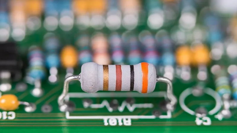
Resistors are among the most fundamental components in electronic circuits, yet identifying their values can be challenging without a clear understanding of color coding. The resistor color code system uses standardized colored bands to represent resistance value, tolerance, and sometimes temperature coefficient, ensuring consistency across manufacturers and applications. Mastering how to read resistor color code is particularly important during circuit assembly, troubleshooting, and design verification, where incorrect resistance values can lead to performance degradation or component failure.
From simple prototyping on a breadboard to complex PCB layouts, knowing how to read resistor color code helps streamline workflow and reduce design errors. This article explores how to read resistor color code through theory, and demonstrates practical methods for reading four, five and six‑band resistors. It further covers the history of the coding scheme, explores tools that simplify the process and offers best‑practice guidance for engineers.
Why Do Resistors Have Color Codes?
The Need for Compact Identification
The large wire-wound, cement, or high-power resistors often have their resistance value, tolerance, and wattage printed directly on the body because sufficient surface area is available. In contrast, the majority of resistors used in digital and analog circuits are small axial lead components, typically rated between 1/8W and 1W. Their cylindrical bodies are too small to support readable alphanumeric markings, especially after exposure to soldering heat, flux residue, and long-term temperature changes.
To solve this limitation, the electronics industry adopted a color-based identification system that remains legible regardless of size or orientation. This system originated in the 1920s, when the radio industry introduced the Radio Manufacturers Association (RMA) resistor color code. The approach proved reliable and scalable, leading to formal international standardization. In 1952, the International Electrotechnical Commission (IEC) codified the system as IEC 62, later updated and published as IEC 60062. [1]
The Electronic Industries Association (EIA) adopted the same scheme for U.S.-manufactured electronic components. Today, this color code is a globally accepted standard used not only for resistors, but also for certain capacitors and inductors, ensuring interoperability across manufacturers and regions.
Preferred Values and the E-Series
It is neither practical nor economical for manufacturers to produce every possible resistance value. Instead, resistors are manufactured in standardized preferred values, selected so that the tolerance ranges of adjacent values overlap. These value sets, known as the E-series, are defined mathematically on a logarithmic scale.
For example, the E12 series, intended for ±10% tolerance resistors, includes values such as 10 Ω, 12 Ω, 15 Ω, 18 Ω, 22 Ω, 27 Ω, and so forth. Once the tolerance tightens, higher-density series are used — such as E24 (±5%), E48 (±2%), E96 (±1%), and E192 (≤0.5%). The resistor color code provides a compact and simple way to encode these preferred values directly on the component body, eliminating the need for printed text.
Basic Structure of the Color Code
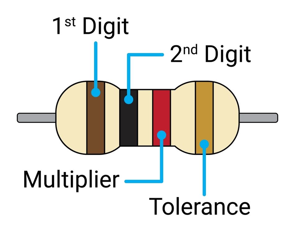
In its most common implementation, the resistor color code uses four bands. The first band and second band represent the significant digits of the resistance value. The third band is the multiplier, indicating a power of ten that scales the digits to the final value in ohms. The fourth band, known as the tolerance band, defines the acceptable deviation from the nominal value.
For higher-precision designs, five-band resistors are used, where the first three bands represent significant digits, allowing finer resolution. In six-band resistors, an additional band specifies the temperature coefficient, typically expressed in ppm/°C, which quantifies how the resistance changes with temperature. [2] The color meanings and band positions are strictly standardized under IEC 60062, ensuring consistent interpretation across suppliers, applications, and industries.
Recommended Reading: What Is a Resistor in a Circuit? Theory, Types, and Practical Applications
Standard Color Code Values
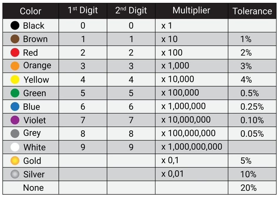
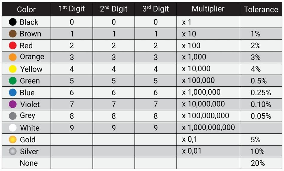
The core of reading resistor bands is memorizing the mapping between colors and numbers. The table below summarizes the IEC 60062 assignments for significant digits, multipliers, tolerance percentages and temperature coefficients. The metallic colors (gold and silver) provide fractional multipliers and specific tolerances, while the temperature‑coefficient codes (ppm/°C) are used on six‑band resistors.
Reading Orientation
Proper orientation ensures the bands are interpreted correctly. Three simple rules help:
1. Locate the Tolerance Band: Gold or silver bands (or their substitutes) are never used for significant digits. Hold the resistor so the metallic band is on the right. If no metallic band is present, look for the wider spacing between bands or the group of bands closer together; the tolerance band is furthest from the other bands.
2. Read Left to Right: Start from the band closest to the lead or the grouped bands and proceed to the tolerance band. Reversing the order yields a drastically different value.
3. Recognize Default Tolerances: Three‑band resistor without a tolerance band defaults to ±20%.
These rules ensure reliable decoding during circuit assembly, troubleshooting, and PCB verification.
Four‑Band Resistors
Structure
Four‑band resistors comprise two significant digits, a multiplier and a tolerance band. They are widely used in general electronics and deliver cost‑effective performance for pull‑ups, LED current limiting and simple dividers. The first digit (1st Band) and second digit (2nd Band) come directly from the color chart. The third band determines the multiplier. The fourth band specifies tolerance, common values are ±1% (brown), ±2% (red), ±5% (gold) and ±10% (silver).
These resistors offer a balance between cost and performance, making them suitable for non-critical applications.
Example
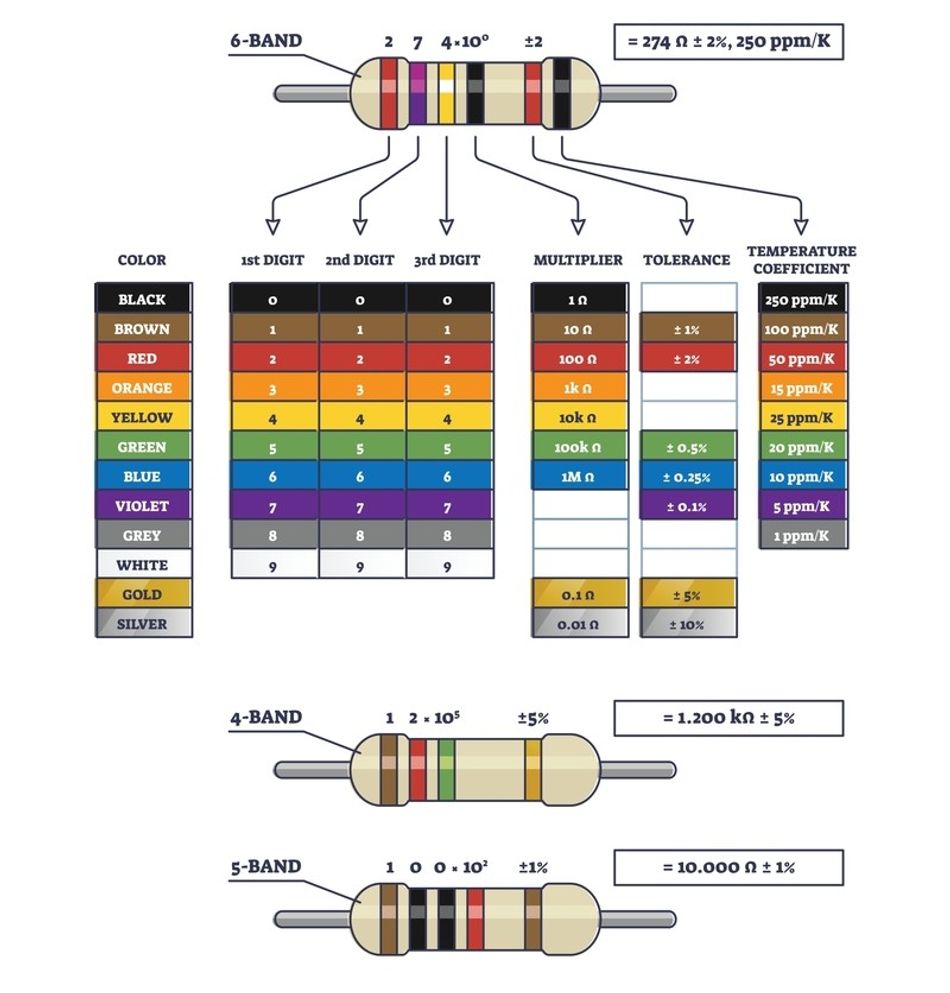
Consider a resistor with yellow, violet, red, and gold color bands. Yellow (4) and violet (7) form the significant digits, while red provides a multiplier of ×10². The calculated resistance value is therefore 47 × 10² = 4700 Ω, or 4.7 kΩ. The gold tolerance band specifies ±5%, meaning the actual resistor value can range from 4.465 kΩ to 4.935 kΩ. This example is frequently used in tutorials because it clearly illustrates how digits, multiplier, and tolerance combine. [3]
Applications
Four‑band resistors suit many digital and analog circuits. They are adequate for pull‑up/pull‑down resistors, LED series resistors, simple RC timing networks and other non‑precision tasks. Because the tolerance is relatively wide (5–10%), designers must verify that the resulting current or voltage variations remain within acceptable margins.
For instance, using a 1 kΩ resistor (brown, black, red, gold) to set LED current with a 5 V supply yields approximately 5 mA. A ±5% tolerance can vary the current by ±0.25 mA, which is usually acceptable.
Five‑Band Resistors
Structure
Five‑band resistors provide a third significant digit of precision. The bands read: three significant digits, a multiplier, and tolerance. These parts commonly have tolerances of ±1% or ±2% and are used in precision analog circuits, instrumentation and measurement equipment.
Example
The resistor marked brown, black, black, red, brown decodes as follows: the first three bands (1, 0, 0) form the significant digits, the fourth band (red) multiplies by ×10², and the fifth band (brown) indicates ±1% tolerance. The resulting value is 100 × 10² = 10 kΩ, ±1%. Such resistors are widely used in precision voltage dividers and active filter networks.
Six‑Band Resistors
Structure
The six‑band resistors are essentially five‑band resistors with an additional band for temperature coefficient or reliability. The bands read: three significant digits, a multiplier, a tolerance and a final band. When used as a temperature coefficient, this band indicates how much the resistance changes with temperature, expressed in parts per million per degree Celsius (ppm/°C).
For example, a brown sixth band denotes 100 ppm/°C; for every 10 °C change, the resistance shifts 0.1%. In military‑specified resistors, the sixth band may instead denote failure rate percentage per 1000 hours.
Example
For a resistor with bands orange, orange, black, brown, brown, blue, the first three bands yield 330, the multiplier (brown) is ×10¹, producing 3300 Ω, or 3.3 kΩ. The fifth band (brown) indicates ±1% tolerance, and the sixth band (blue) specifies 10 ppm/°C, meaning the resistance changes by only 0.01% per 10 °C. Such resistors are used in precision references, instrumentation amplifiers, and temperature-sensitive measurement systems.
Body‑End‑Dot System and Legacy Codes
Before the modern resistor color bands system became universal, some resistors used a body‑end‑dot scheme: the body color represented the first significant digit, the end color indicated the second digit, and a dot or central band specified the multiplier. The second dot or the opposite end color denoted tolerance. This method was common before World War II and is rarely encountered today. It’s still worth recognizing if servicing vintage equipment.
Exceptions and Special Cases
Zero-Ohm Resistors
The component marked with a single black band is not a true resistor but a zero-ohm resistor, effectively functioning as a jumper. It allows automated assembly machines to place wire links using standard resistor packaging. [4] Zero-ohm resistors are commonly used on Printed Circuit Boards (PCBs) for routing flexibility, configuration options, and signal bridging without adding measurable resistance.
High-Voltage Resistors without Metallic Bands
In high-voltage applications, gold and silver bands are often avoided because their metallic particles can reduce insulation strength and increase leakage risk. Instead, manufacturers substitute yellow and gray bands to indicate ±5% and ±10% tolerance, respectively. Designers working with high-voltage circuits should always verify tolerance markings against the manufacturer’s datasheet rather than relying on standard metallic conventions.
Reliability Band
Some military-specified resistors include an additional reliability band that indicates failure rate, typically expressed as a percentage per 1,000 hours of operation. These markings follow military standards such as MIL-HDBK-199 and are rarely used in commercial electronics. They are mainly relevant in aerospace, defense, and mission-critical systems.
Temperature Coefficient Band
In six-band resistors, the final band specifies the temperature coefficient, expressed in ppm/°C, indicating how much the resistance value changes with temperature. The typical values include brown (100 ppm/°C), red (50 ppm/°C), orange (15 ppm/°C), yellow (25 ppm/°C), blue (10 ppm/°C), and violet (5 ppm/°C). Lower ppm values signify better thermal stability, which is essential in oscillators, precision references, and instrumentation circuits.
Recommended Reading: Current-Limiting Resistor: Theory, Design and Practical Applications for Engineers
Step-by-Step Method for Reading Color Codes
1. Orient the Resistor: Hold the resistor so that the tolerance band (gold, silver, yellow or gray) is on the right and the colored bands are grouped to the left.
2. Determine the Band Count: Count the number of distinct bands. Three‑band resistors have two digits and a multiplier with a default ±20% tolerance; four‑band resistors have two digits, a multiplier and a tolerance; 5 band resistors have three digits, a multiplier and a tolerance; six‑band resistors add a temperature‑coefficient or reliability band.
3. Read the Significant Digits: Identify the colors of the first two or three bands and convert them to digits using the standard color code chart.
4. Apply the Multiplier: Use the color of the multiplier band to determine the power of ten by which to multiply the significant digits.
5. Account for Tolerance: Interpret the tolerance band to know how far the actual resistance may vary from its nominal value.
6. Consider Temperature Coefficient or Reliability: For six‑band resistors, read the final band to determine the temperature coefficient or failure rate.
7. Verify with a Multimeter: When precision matters, or bands are faded, use a multimeter to confirm the actual resistance value.
Following this structured approach ensures accurate decoding in both design and troubleshooting. For complex projects, engineers often supplement manual reading with resistor color code calculators or mobile apps, which speed up verification and reduce interpretation errors.
Recommended Reading: Circuit Color Chart: A Comprehensive Guide for Engineers
Tools and Resources
Online Calculators and Apps
There are several reliable online tools that simplify decoding the resistor color code, especially when working quickly or dealing with unfamiliar band combinations. Interactive calculators allow users to select resistor color bands visually and instantly compute value of the resistor, tolerance, and temperature coefficient (where applicable). These tools are particularly useful when color bands are difficult to distinguish or when verifying calculations during design reviews.
There are multiple applications, useful for field engineers who need to identify resistor values without carrying reference charts.
Multimeters and LCR Meters
Despite the convenience of color codes, measurement is still necessary in certain situations. The faded bands, ambiguous colors or counterfeit components can cause misinterpretation. Digital multimeter or LCR meter provides a direct measurement of resistance in ohms, eliminating guesswork. In high-precision or high-reliability applications, designers often measure samples from each production batch to confirm compliance with specified tolerance and thermal behavior.
Pocket Reference Charts and Mnemonic Devices
Many engineers carry laminated charts or printouts of the color code. Mnemonic sentences help memorize the color order. The examples include “Better Be Right Or Your Great Big Venture Goes Wrong” and “Bad Boys Race Our Young Girls But Violet Generally Wins,” where the first letter of each word corresponds to a color. Mnemonics should be used as memory aids, not as substitutes for proper references when accuracy is critical.
Practical Design Considerations
Tolerance and Circuit Performance
Tolerance defines how much the actual resistance of a resistor can deviate from its nominal value. For example, a ±5 % 10 kΩ resistor may vary between 9.5 kΩ and 10.5 kΩ. This variation affects circuit parameters such as voltage divider ratios, LED current, and timing in RC networks. In digital circuits, tolerance can influence input thresholds or bias points. Once tight tolerances are required, such as in instrumentation amplifiers, analog‑to‑digital converter reference networks or precision oscillators, engineers should choose ±0.5 % or ±0.1 % resistors (green or blue tolerance bands, respectively).
Temperature Coefficient and Thermal Stability
The resistance of a material changes with temperature. The temperature coefficient (ppm/°C) quantifies this change. For example, a 10 kΩ resistor with a temperature coefficient of 50 ppm/°C will change by 0.05 Ω per degree Celsius. Over a 50 °C temperature swing, that change is 25 Ω, which may be unacceptable in precision circuits. High‑precision resistors use materials like metal film and have low temperature coefficients (5 ppm/°C or less). Engineers must consider the operating temperature range of the design and select resistors accordingly.
Power Rating and Physical Size
The physical size of a resistor indicates its wattage rating, although not encoded by color bands. The larger the resistor, the more power it can dissipate. Designers should ensure that the chosen resistor can handle the anticipated power without overheating. Derating curves in datasheets provide guidance. Using an undersized resistor can cause excessive temperature rise, altering its resistance and potentially leading to failure.
E-Series Selection and Inventory Efficiency
Choosing the appropriate E-series balances design accuracy with inventory efficiency. Lower-order series suit general-purpose designs, while higher-order series support precision requirements with finer value resolution.
High-Voltage and High-Frequency Considerations
In high-voltage circuits, non-metallic tolerance bands may replace gold or silver to maintain insulation integrity. For high-frequency designs, parasitic inductance and capacitance dominate, and surface-mount resistors with numeric codes are often preferred. Datasheet verification is essential to ensure suitability in these advanced applications.
Common Mistakes and How to Avoid Them?
Even experienced engineers occasionally misread resistor bands. Here are frequent pitfalls and strategies to prevent them:
Reading from the Wrong End: It is better to locate the tolerance band or spacing and read left to right.
Misinterpreting Similar Colors: Red and orange, green and blue or gray and white can be confused under poor lighting. Use proper lighting, magnification or a multimeter for verification.
Overlooking Default Tolerances: Three‑band resistors without a tolerance band default to ±20%. Failing to account for this can lead to large errors.
Ignoring Temperature Coefficient: In precision circuits, neglecting the sixth, last band can result in temperature‑dependent drift.
Assuming all Resistors are Color‑Coded: Surface‑mount resistors use printed codes (e.g., “103” for 10 kΩ). It is always necessary to check the package type.
Not Verifying Suspicious Parts: Counterfeit components or those with faded bands may have incorrect colors. Use a multimeter to confirm values.
By being mindful of these issues and using measurement tools or calculators, engineers can avoid costly mistakes.
Surface‑Mount Resistor Codes
While axial leaded resistors rely on color bands, surface‑mount resistors (SMD) typically use alphanumeric codes printed on the package due to space constraints. The common three‑digit codes represent two significant figures and a multiplier (e.g., “472” for 4.7 kΩ). Four‑digit codes provide three significant figures and a multiplier (e.g., “1002” for 10.0 kΩ). The letter “R” indicates a decimal point (e.g., “4R7” for 4.7 Ω). Tolerances are implied by the E‑series of values and are specified in the datasheet. Although not part of the color code standard, SMD markings follow similar principles and serve the same purpose.
Future Trends and Alternative Marking Methods
The advances in electronics manufacturing, miniaturization, and automation are steadily reshaping how resistor values are identified. Surface-Mount Technology (SMT) continues to dominate modern PCB design. The traditional resistor color bands are increasingly replaced by laser-etched numeric codes, high-contrast alphanumeric markings, and machine-readable identifiers. Laser marking improves durability, resists fading during reflow soldering, and supports tighter component spacing demanded by high-density designs.
In high-precision and industrial applications, manufacturers are introducing 2D data matrix codes directly on resistor bodies or packaging. These codes can encode not only resistance value and tolerance, but also temperature coefficient (ppm), production batch, date code, and traceability data. This aligns with Industry 4.0 practices, enabling automated optical inspection (AOI), digital inventory management, and improved quality control across global supply chains.
Research and pilot implementations are also exploring RFID-enabled passive components, particularly for aerospace, automotive, and defense sectors. RFID tagging allows non-contact identification during assembly, maintenance, and lifecycle tracking, reducing human error and supporting predictive maintenance strategies. While cost and size constraints currently limit widespread adoption, ongoing advances in ultra-thin and printable RFID technology continue to push feasibility forward.
Despite these developments, color-coded through-hole resistors remain relevant in education, prototyping, repair work, and hobbyist platforms such as Arduino-based systems. Mastery of color codes provides essential foundational knowledge, helping engineers transition seamlessly from legacy components to modern, data-driven marking technologies.
Conclusion
The resistor color code is a concise and internationally standardized method for indicating resistance, tolerance and temperature characteristics. By reading the bands in order—significant digits, multiplier, tolerance, and optional temperature coefficient—engineers and students can quickly determine resistor values without test equipment. The IEC 60062 standard defines the mappings between colors and numeric values, ensuring cross‑manufacturer consistency. Practical skills include correctly orienting the resistor, using calculators or multimeters for verification, and considering tolerance and temperature coefficients in circuit design. As electronics continues to evolve, surface‑mount codes and digital identification methods will complement color bands rather than replace them. Mastery of the resistor color code equips engineers with a timeless tool for efficient design, troubleshooting and education.
Frequently Asked Questions (FAQs)
1. What do the different bands on a resistor mean?
A. The bands encode the resistor value: the first two or three bands show significant digits, the next band is the multiplier, and the final band indicates tolerance. Six-band resistors add temperature coefficient or reliability information.
2. How can I tell which end of the resistor to start reading from?
A. Identify the tolerance band first. It is usually gold, silver, yellow, or gray and spaced farther apart. Hold this band on the right and read the remaining color bands from left to right.
3. What is the difference between a four-band and a five-band resistor?
A. Four-band resistors use two significant digits, a multiplier, and a tolerance band. Five-band resistors add a third significant digit, allowing higher precision values, typically with ±1% or ±2% tolerance.
4. What does the sixth band on a resistor indicate?
A. The sixth band specifies temperature coefficient in ppm/°C or, in some military-grade resistors, long-term reliability. Lower ppm values indicate better thermal stability in precision and temperature-sensitive circuits.
5. Why are gold and silver bands sometimes absent from high-voltage resistors?
A. Gold and silver contain metallic pigments that can reduce insulation strength. High-voltage resistors replace them with yellow or gray bands to indicate tolerance while maintaining electrical isolation.
6. How do I deal with faded or unclear color bands?
A. Measure the resistor directly using a digital multimeter. Color-code calculators can help confirm values, but for critical designs, always verify against the manufacturer’s datasheet or replace uncertain components.
7. Do surface-mount resistors use color bands?
A. No. Surface-mount resistors use printed numeric codes instead of color bands. These codes represent significant digits and a multiplier, such as “472” for 4.7 kΩ or “4R7” for 4.7 Ω.
References
[1] IEC Webstore. IEC 60062:1952 [Cited 2026 January 5] Available at: Link
[2] Panasonic. Resistor Color Codes: Thorough Explanations of How to Interpret, Calculate, and Remember Them? [Cited 2026 January 5] Available at: Link
[3] DigiKey. 4 Band Resistor Color Code Calculator [Cited 2026 January 5] Available at: Link
[4] Wikipedia. Zero-Ohm Resistor [Cited 2026 January 5] Available at: Link
in this article
1. Key Takeaways2. Introduction3. Why Do Resistors Have Color Codes?4. Standard Color Code Values5. Four‑Band Resistors6. Five‑Band Resistors7. Six‑Band Resistors8. Body‑End‑Dot System and Legacy Codes9. Exceptions and Special Cases10. Step-by-Step Method for Reading Color Codes11. Tools and Resources12. Practical Design Considerations13. Common Mistakes and How to Avoid Them?14. Surface‑Mount Resistor Codes15. Future Trends and Alternative Marking Methods16. Conclusion17. Frequently Asked Questions (FAQs)18. References