Circuit Color Chart: A Comprehensive Guide for Engineers
An insight into applying color codes for electrical applications. This guide enlightens engineers and designers about standard color codes for resistors, inductors, capacitors, network cabling and power wiring to help improve accuracy, safety and maintainability in design projects.

10 Oct, 2025. 11 minutes read
Key Takeaways
Electrical failures are among the primary causes of fires and fatalities in the industrial sector. Standardized color schemes and codes can reduce such mishaps and improve casualty rates.
More than just aesthetics, color codes provide critical information about component values, such as resistance, temperature coefficients, wire functions (neutral, ground, live), and networking pinouts.
There are different color code standards, and the Electrotechnical Commission (IEC), United States, United Kingdom, Canada, and other regions have different color schemes for DC and AC designs. In networking, T568A and T568B are two widely used wiring schemes.
The color codes in resistors and capacitors represent multipliers. Tolerances are encoded by colored bands or dots; In addition to that, the precision components also include bands for temperature coefficient and dependability.
This article will discuss accessibility in future trends. Digital design platforms use color charts directly in schematics. Moreover, the modern tools can help color-blind engineers with electronic readers and patterns.
Introduction
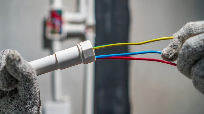
Color is more than just a decorative element in contemporary electronics and power systems; it is a code. Colors tell the story whether you are crimping an RJ45 connector for a network switch, wiring a three-phase motor in a factory, or choosing a resistor for an embedded system. Reliability and safety depend on being able to correctly interpret that story.
The stats between 2015 and 2019 suggest some intriguing facts about the importance of color coding. Fire departments in the United States handled an average of 46,700 home fires caused by electrical failure or malfunction, which resulted in 390 civilian fatalities and $1.5 billion in property damage, according to the National Fire Protection Association.
In this article, we will discuss circuit color charts. You will see various color coding conventions that engineers use in digital design and hardware layouts. We will discuss the theory behind electronic color codes, practical wiring standards, and network cabling. Interesting tables, diagrams, and real-time stats will help you strengthen your understanding and the need for circuit color charts.
Color Codes in Electrical and Electronic Circuits
Electrical systems use color coding as a universal language. Without the need for translation or measurement, it offers immediate recognition of conductor functions and component values.
The procedure began in the early days of radio production and has now evolved into a set of official guidelines. Authorities like the Telecommunications Industry Association (TIA), the National Electrical Code (NEC) in the US, and the International Electrotechnical Commission (IEC) now require color codes. A circuit color chart is necessary for the reasons listed below:
Identifying Wires—Color codes help identify wiring for AC and DC power distribution. Hence, it makes it easier and safer for electricians to distinguishbetween ground, neutral, and live conductors.
Complying with Existing Standards—In many regions, there are strict laws that require specific colors. For example, the IEC standards require green-yellow insulation for protective earth conductors.
Easy Maintenance—Technicians can easily track components and circuits without needing to verify from schematics. Hence, proper color coding can help streamline troubleshooting and optimize maintenance time.
Personnel Safety—Miswiring can often lead to equipment damage, shock, and fire. When designs are clearly labelled and color-coded, it lowers the mentioned risks.
In electronics and electrical design, color codes address a wide range of applications from small passive components to high-power systems.
Color Codes for Resistors in Electrical Design
Resistors are one of the most fundamental and prevalent passive parts of analog and digital circuits. Manufacturers utilize colored bands to encode resistance value, tolerance, and occasionally temperature coefficient because many are too small to print numerical values on.
Color Bands in Resistors
IEC 60062:2016 defines the current standard for resistor color codes. It recommends the use of three to six bands that are positioned around a cylindrical resistor's body. Every band has a unique meaning:
Significant Digits—The resistance value's most important digits are represented by the first two bands (and a third for high-precision resistors).
Multiplier—The power-of-ten multiplier is represented by the next band.
Tolerance—The percentage tolerance is indicated by an optional band; its absence indicates a 20% tolerance.
Temperature Coefficient—In temperature-sensitive applications, the temperature coefficients are added as fifth or sixth bands. It indicates parts per million temperature coefficient and reliability.
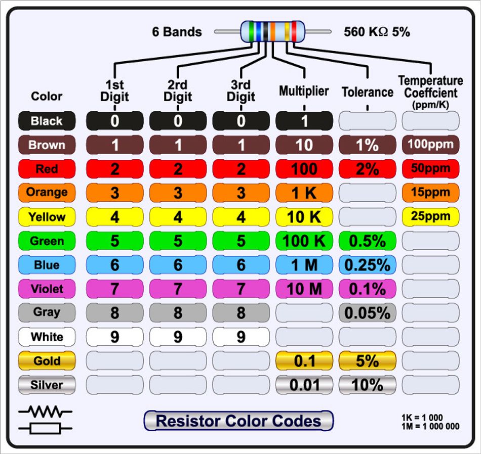
Color Chart for resistors
The following figure summarizes the standard resistor color code. The colors and their positions represent numerals, tolerances, and multipliers. The figure indicates values as per the IEC 60062 standard.
Four‑band Resistors
The first two bands of a typical resistor with four bands are used for numbers, the multiplier is used for the third band, and the tolerance is used for the fourth band. For example, Red, violet, green, and gold represent the numbers 2 and 7, a multiplier of 10⁵, and a tolerance of ±5%: 2.7 MΩ ±5%. If the tolerance band is absent, the default tolerance is ±20%.
Although they are uncommon nowadays, three-band resistors only encode numbers and multipliers, suggesting a 20% tolerance. For high-precision applications, five- and six-band resistors add a third digit and a temperature coefficient band.
A reliability band that shows the failure rate per 1,000 hours may be present in military or space-grade resistors. While color bands indicate values in cylindrical resistors, numbers are used in SMD resistors to indicate resistance values.
Special Cases and Mnemonics
Resistor color codes mentioned above apply to most common applications. However, some special scenarios need specialized indicators for user safety and design.
Zero-Ohm Resistors—Zero-ohm resistors are simply wire links. They are identified by a single black band. Their purpose is to resemble resistors for automated assembly.
Reliability band—These bands show the failure rate of a resistor. This is an additional band and may not be present in all resistors.
Mnemonics - These are typically used by technicians to remember the numeric representation of each color. There are several popular mnemonics, but a simple way to remember the codes is that black represents 0 and white represents 9. The middle digits are the rainbow colors—red, orange, yellow, green, blue, and violet.
Further Reading: Resistor Chart: Comprehensive Guide to Resistor Values, E-Series, and Color Codes
Capacitor and Inductor Color Codes
While resistors are common use cases for color coding, capacitors and inductors occasionally use similar schemes. In cylindrical capacitors, usually, four or more colored bands or dots are used to indicate different values. The capacitance's significant digits in picofarads are represented by the first two colors, the decimal multiplier by the third, and tolerance, voltage rating, or temperature coefficient by the following bands. For example, if a capacitor has a color code:
The color scheme may represent 34 × 10² pF (3.4 nF).
Tolerance (±5%, ±10%) is represented by additional bands like gold or silver.

The outer electrode of certain capacitors is indicated by wide black bands; noise pickup is decreased by connecting this end to chassis ground.
Suggested Reading: Decoding Capacitor Codes: A Comprehensive Guide for Engineers
To indicate inductance in microhenries, small inductors frequently use the resistor color code; a white band could signify unique requirements.
Sometimes colored rings are used to encode the numeric part of the part number on diodes with JEDEC "1N" codes.
For example, the 1N4148 diode, for instance, can be labeled as yellow-brown-yellow-grey.
Suggested Reading: PCB Components: A Comprehensive Technical Guide to Passive, Active, and Electromechanical Parts
Wiring Color Codes for AC and DC Power
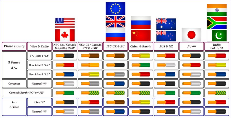
In power circuits, the colors of the wire insulation indicate each conductor's function. There are several standards because safety laws differ across the globe. The most popular schemes are compiled in the following tables.
IEC (Most of Europe) AC Wiring
The IEC standard is followed in most European countries. The following table specifies the IEC wiring color standards.
Function | Color | Notes |
Green–yellow | The protective earth conductor is green with yellow stripes. | |
N (neutral) | Blue | Used in single‑phase and three‑phase systems. |
L / L1 | Brown | Line conductor for single‑phase; phase L1 in three‑phase systems. |
L2 | Black | Phase 2 in three‑phase systems. |
L3 | Grey | Phase 3 in three‑phase systems. |
United Kingdom AC Wiring
The UK started following the IEC color standards in 2004. Earlier, it used different colors in domestic installations. Therefore, technicians and engineers must consult the local regulations when adding new wiring to existing installations. The following table shows the current and obsolete colors:
Function | IEC color | Old UK color |
PE | Green–yellow | Green–yellow |
N | Blue | Black |
L (single phase) | Brown | Red |
L1 (three phase) | Brown | Red |
L2 | Black | Yellow |
L3 | Grey | Blue |
AC Wiring in the United States
The United States follows the th National Electrical Code (NEC). It requires bare, green, or green-yellow for protective ground and white or grey for neutral. Black, red, and blue are commonly used for 208 V three-phase systems. For 480V systems, brown, orange, and yellow may be used. The standard also specifies that the conductors' ends must be larger than 6 AWG, and are usually color-taped and black.
AC Wiring in Canada
According to the Canadian Electrical Code (CEC), three-phase wires are red, black, and blue, single-phase hot wires are black (and red for a second hot), neutral is white, and ground is green or green-yellow.
Standards for DC Wiring
Data centers and solar installations are covered by the IEC DC standard. Blue is used for mid-wire or negative earthing, grey for negative, and brown for positive. The NEC in the United States requires that ground be green/green-yellow, positive be red, negative be black, and grounded neutral be white/grey.
System | Conductor | Color (IEC) | Color (U.S.) |
Protective earth | PE | Green–yellow | Bare, green or green–yellow |
Positive (+) | L+ | Brown | Red |
Negative (–) | L– | Grey | Black |
Mid‑wire / neutral | M | Blue | White/Grey |
Network Cabling and RJ45 Color Codes
In data networks, the twisted pair cable is mostly terminated by the RJ45 connector. Network engineers follow the ANSI/TIA-568 standard, which defines two pinout schemes:
T568A
T568B
In both standards, the eight conductors are assigned to an eight-position modular connector. The difference lies in the assignment of orange and green pairs.
T568A vs. T568B
The following table summarizes the comparison between the T568A and T568B standards.
T568A | T568B | |
Valid Wiring Scheme | Both are valid standards with no technical superiority. | |
Origin | Follows telephone standards (USOC) | Built on the AT&T 258A commercial standard. |
Color Assignment | Starts with a Green-white pair | Starts with an Orange-white pair |
Applications | Used in residential wiring | Used in commercial applications |
Crossover Cables | If one end follows T568A and the other follows T568B, the cable is in a crossover orientation. |
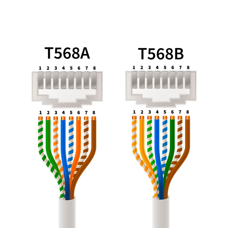
Typical Pin Assignments for T568A and T568B
Although the following diagram can vary by manufacturer, a standard Category 5/6 cable uses four twisted pairs: blue, orange, green and brown.
Each pair has a solid color paired with a white‑striped wire. When terminating a plug, untwist each pair only as far as necessary to avoid performance degradation. Pin assignments for T568A and T568B are shown in the following diagram:
For network designers, it is important to choose one scheme and apply it consistently across the installation. Many patch panels and jacks are labeled internally with both schemes to guide termination.
For network designers, it is important to choose one scheme and apply it consistently across the installation. Many patch panels and jacks are labeled internally with both schemes to guide termination.
Recommended Reading: The Future of Wired Communication Infrastructure: Single Pair Ethernet
Safety, Compliance and Best Practices
Color coding is most effective when sound engineering and regulatory compliance are combined. The National Electrical Code (NEC), ANSI/TIA‑606‑B and other standards provide comprehensive guidelines for safe wiring.
Fig 5: An engineer testing electrical systems while observing the safety protocols
Here are some recommendations for safe wiring.
Before turning on the power, make sure that every conductor is connected in accordance with the design schematic.
Use simple testers to identify open connections or reversed polarity.
Use structured labeling specified by ANSI/TIA 606-B to identify circuits, voltage levels, and functions.
Observe established color schemes. Generally, differentiating between hot, neutral, and ground conductors is made simpler by using approved color schemes.
Conduct functional tests and compare the completed installation to the schematics.
Make sure the surge protection and grounding are correct. The NEC encourages routine ground resistance testing and requires ground-fault circuit interrupters (GFCIs) in areas that are prone to moisture.
Distribute loads among circuits, use circuits specifically designed for high-power equipment, and use smart panels to keep an eye on load levels.
Suggested Reading: Electrical Testing: Comprehensive Guide for Engineering Professionals
Complying with these practices not only reduces the risk of accidents but also enhances system reliability and simplifies troubleshooting.
Practical Implementation Tips for Engineers
Color code implementation is all about careful planning and discipline. Here are some suggestions that will help engineers successfully implement color coding in their projects.
Pick Appropriate Standards
It is important to pick the desired standard, such as IEC, NEC, CEC, or others, at the start of the project. Moreover, all stakeholders must be on the same page regarding the standard, so it’s important to document the selection of standards.
Create a Circuit Color Chart
A circuit color chart can streamline the implementation for technicians. Therefore, prepare a color chart for your design and include all the components, i.e., resistors, capacitors, inductors, RJ45, etc., for easy reference.
Color-Blind Accessibility
It’s essential to design with the perspective of color-blind personnel who might be operating at the project site. Additional text, symbols, and labels can make it easier for everyone to read the schematic accurately.
Component Reliability
The electrical components must be sourced from reputable suppliers. It ensures that the values mentioned in the color coding will be highly accurate and will reduce the chances of any mismatches later in the project. Moreover, it’s a good idea to consult datasheets to ensure alignment.
Use Documentation and Labeling Software
Several modern tools allow users to automate label creation in schematics and layouts. This is especially helpful as these tools are compliant with ANSI/TIA standards.
Double Check Tests
While most color-coded devices are accurate, it is always a good idea to check the devices manually. Use multimeters or testers to confirm component specifications and that they perform as expected.
Future Trends and Innovations
The concept of a circuit color chart continues to evolve with technology and design practices. Some noteworthy trends include:
Digital visualization. Modern EDA tools overlay color codes on schematic diagrams and 3D board layouts, reducing the need for paper charts.
Adaptive displays and readers. Smartphone apps and handheld devices can scan resistor bands or wire colors and display values, assisting both professionals and hobbyists.
Enhanced materials. Advances in polymer science enable brighter, more durable insulation colors and multi‑layer PCBs with colored solder masks that aid debugging.
Accessibility innovations. Patterns, textures, and augmented‑reality overlays help color‑blind engineers interpret color codes accurately, fostering inclusivity.
Smart cables. Embedded chips in cables may soon provide digital identification of wiring schemes and compatibility, reducing reliance on color alone.
Conclusion
In electrical and electronic engineering, color codes hold a pivotal value. They are the unspoken language for circuits. The circuit color chart is a vital tool for designers and technicians, as it shows everything from the resistor color bands that subtly indicate whether a component is 220 Ω or 2.2 kΩ to the wire colors that prevent you from connecting line to neutral.
Respecting regional standards like IEC, NEC, and TIA helps to prevent misunderstandings, accidents, and maintenance hassles. The stakes are highlighted by fire and injury statistics. You can create systems that are safe, maintainable, and functional by labeling your circuits, incorporating color charts into your workflow, and keeping up with changing standards.
Frequently Asked Questions (FAQs)
Why are circuit color charts important in electrical engineering?
A color chart is an easy-to-use resource that provides a quick reference for interpreting color codes on components and wires. It helps in reducing errors, speeds up troubleshooting and ensures compliance with regulations. If color charts are not effectively employed, it could lead to misinterpreting colors and cause equipment failure, shock, or fire.
2. How do I read a resistor color code?
To read a resistor code, always start at the end with grouped bands and read from left to right. The first two bands (three in precision resistors) give the digits, the next band is the multiplier, and the final band is the tolerance. For example, red–violet–green–gold means 2 7 ×10⁵ Ω with a ±5 % tolerance.
3. What is the difference between T568A and T568B wiring?
Both schemes are approved pinouts for RJ45 connectors. They differ only in the order of the green and orange pairs; T568A starts with the white–green pair while T568B starts with white–orange. As long as both ends of a cable use the same scheme, performance is identical.
3. Are wiring color codes universal across countries?
There are different wiring color standards throughout the globe. Europe follows IEC colors (brown for live, blue for neutral, and green–yellow for earth), while the U.S. NEC uses black/red/blue for phase conductors, white or grey for neutral and green or bare for ground. Always check local standards before wiring.
5. How can color‑blind engineers work with color codes?
Many organizations supplement colors with patterns, text labels or barcodes. Electronic testers and smartphone apps can decode color bands and display values, reducing reliance on color perception.
6. Do capacitors and inductors use the same color code as resistors?
Capacitors sometimes use colored bands or dots, but the code is not identical. The first two bands represent the capacitance digits, the third is the multiplier and additional bands may indicate tolerance or voltage rating. Small inductors often use the resistor color code for inductance.
References
DuraLabel, "How to avoid costly electrical wiring mistakes," [Online]. Available: https://resources.duralabel.com/articles/how-to-avoid-costly-electrical-wiring-mistakes
All About Circuits, "Wiring Color Codes," [Online]. Available: https://www.allaboutcircuits.com/textbook/reference/chpt-2/wiring-color-codes/
Wikipedia, "Wikipedia," [Online]. Available: http://en.wikipedia.org
Comms Express, "T568A and T568B wiring standards," [Online]. Available: https://www.comms-express.com/infozone/article/t568a-and-t568b/
Arrow Electronics, "Resistor Color Code," [Online]. Available: https://www.arrow.com/en/research-and-events/articles/resistor-color-code
in this article
1. Key Takeaways2. Introduction3. Color Codes in Electrical and Electronic Circuits4. Color Codes for Resistors in Electrical Design5. Capacitor and Inductor Color Codes6. Wiring Color Codes for AC and DC Power7. Network Cabling and RJ45 Color Codes8. Safety, Compliance and Best Practices9. Practical Implementation Tips for Engineers10. Future Trends and Innovations11. Conclusion12. Frequently Asked Questions (FAQs)13. References