Current Divider Rule: Formula, Derivation, and Worked Example
Current division is the principle that determines how electric current splits between parallel branches according to their resistance. This guide explains how to calculate the exact current in each branch using Ohm's law and Kirchhoff's current law, with practical examples and limitations.

27 Jul, 2026. 13 minutes read
Current divider
Key Takeaways
● A current divider is a parallel network that splits total current among branches.
● The lower-resistance branch carries more current because every parallel branch has the same voltage across it.
● For two resistors, each branch current uses the other branch resistance in the numerator: I₁ = IT R₂/(R₁+R₂).
● For three or more branches, the conductance form is usually clearer: Ik = IT Gk/ΣGj, where Gk = 1/Rk.
● The current divider is the parallel-circuit counterpart of the voltage divider rule, which applies to series circuits.
● Real designs must account for resistor tolerance, source and load loading, power dissipation, temperature drift, parasitic impedance, and measurement burden.
● Current dividers appear in shunted ammeters, current sensing, bias networks, current mirrors, and power-sharing networks.
Introduction
A current divider is one of the simplest and most useful circuit analysis patterns in electrical engineering. It answers a common question: when a known current reaches a node with two or more parallel paths, how much current flows through each branch?
The answer depends on the relative impedance of each branch. In a DC resistive divider, this means branch resistance. In an AC or transient divider, the same idea applies to complex impedance or admittance. The core concept is still the same: current favors the path with lower impedance, and the total current is the sum of all branch currents.
This makes current division central to series and parallel circuits, analog front ends, current measurement, load sharing, biasing, and transistor circuits. It is also a practical shortcut. Instead of solving for every node voltage first, engineers can often calculate branch currents directly from current ratios.
Recommended reading: Parallel vs Series Circuits: Differences, Theory, and Practical Applications
What Is a Current Divider?
A current divider is a parallel circuit in which an input current splits among multiple branches. Each branch is connected across the same two nodes, so each branch has the same voltage. If the branches contain resistors, the branch with the smallest resistance carries the largest current.
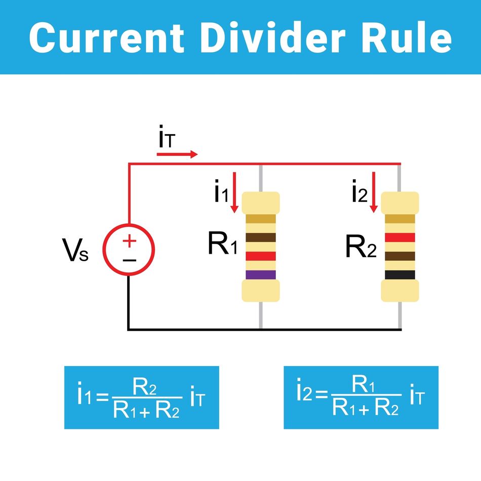
For a two-branch divider with resistors R1 and R2 in parallel, the source current IT splits into I1 and I2:
IT = I1 + I2
Because the branch voltages are equal:
V1 = V2 = V
Using Ohm's law, a lower resistance produces a higher branch current for the same voltage. That is why current division is inverse with resistance, not direct with resistance.
A current divider can be driven by a current source, or it can appear inside a voltage-driven network after the total current into the parallel combination has been found. If the source is a voltage source, first calculate the equivalent parallel resistance and total current, then apply the divider rule.
Current Divider Formula
There's a simple two-resistor version for the most common case and a general conductance-based version that scales to any number of parallel branches.
Two-resistor current divider formula
For two resistors in parallel, R1 and R2, with total current IT entering the parallel combination:
I1 = IT (R2) / (R1 + R2)
I2 = IT (R1) / (R1 + R2)
The formula can look counterintuitive because the current through R1 contains R2 in the numerator. This is correct. Current divides inversely with resistance, so a larger value of R₂ makes branch 1 carry a larger fraction of total current.
A useful ratio form is:
(I1) / (I2) = (R2) / (R1)
So if R2 is three times R1, then the current through R1 is three times the current through R2.
N-branch current divider formula
For three or more branches, the cleanest form uses conductance. Conductance is the reciprocal of resistance:
Gk = (1) / (Rk)
Total conductance in parallel is:
GT = G1 + G2 + ... + Gn = Σ(j=1..n) Gj
The current in branch k is
Ik = IT (Gk) / (GT)
Substituting Gk = 1/Rk gives the resistance form:
Ik = IT (1/Rk) / (Σ(j=1..n) 1/Rj)
You may also see the equation written with equivalent resistance R(eq):
Ik = IT (R(eq)) / (Rk)
where:
(1) / (R(eq)) = Σ (j=1..n) (1) / (Rj)
This works because R(eq)/Rk is the same as (1/Rk)/Σ(1/Rj)
Derivation From Ohm's Law and Kirchhoff's Current Law
The current divider rule follows directly from Ohm's law and Kirchhoff's current law.
Consider n resistors connected in parallel. Since all branches share the same two nodes, each branch has the same voltage V. For branch k:
Ik = (V) / (Rk)
Using conductance:
Ik = V Gk
Kirchhoff's current law states that the current entering a node equals the sum of the currents leaving that node. Therefore:
IT = I1 + I2 + ... + In
Substitute Ik = VGk for each branch:
IT = V G₁ + V G₂ + ... + V Gₙ
Factor out V:
IT = V(G1 + G2 + ... + Gn)
IT = V Σ(j=1..n) Gj
Solve for the common branch voltage:
V = (IT) / (Σ(j=1..n) Gj)
Now substitute this voltage back into the branch-current equation:
Ik = V Gk
Ik = (IT) / (Σ(j=1..n) Gj) Gk
Ik = IT (Gk) / (Σ(j=1..n) Gj)
That is the general current divider rule.
For two resistors, substitute G1 = 1/R1 and G2 = 1/R2:
I1 = IT (1/R1) / (1/R1 + 1/R2)
Multiply the numerator and denominator by R₁R₂:
I1 = IT (R2) / (R1 + R2)
Similarly:
I2 = IT (R1) / (R1 + R2)
Recommended reading: KCL Circuit Analysis: Advanced Engineering Methods & Best Practices
Current Divider vs Voltage Divider
The current divider and voltage divider are dual ideas, but they apply to different circuit topologies.
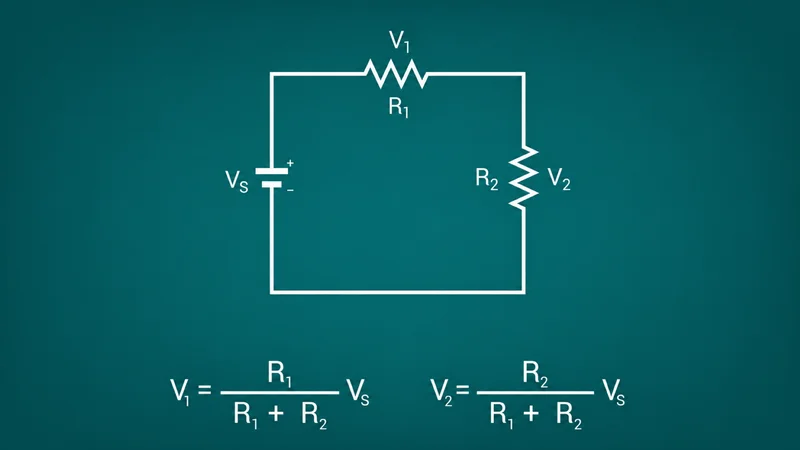
A voltage divider is a series circuit. The same current flows through every element, and the total voltage divides in direct proportion to resistance:
Vk = VT (Rk) / (ΣRj)
A current divider is a parallel circuit. The same voltage appears across every branch, and the total current divides in direct proportion to conductance, or inverse proportion to resistance:
Ik = IT (Gk) / (ΣGj)
For two resistors:
I1 = IT (R2) / (R1 + R2)
The contrast is important. In a voltage divider, the resistor of interest is in the numerator. In a two-resistor current divider, the opposite resistor is in the numerator. Many calculation errors come from applying the voltage-divider form to a parallel network.
Use the voltage divider rule when components are in series and you need voltage drops. Use the current divider rule when components are in parallel and you need branch currents.
Recommended reading: What Is a Resistor in a Circuit? Theory, Types, and Practical Applications
Worked Examples
Two complete numeric examples, one with two resistors and one with three, each checked independently against Kirchhoff's current law.
Example 1: Two-resistor current divider
Problem: A 20 ohm resistor and a 60 ohm resistor are connected in parallel across a 30 V supply. Find the current through each resistor and the total supply current.
First, calculate the equivalent resistance:
R(eq) = (R1R2) / (R1+R2)
R(eq) = (20 × 60) / (20 + 60) = (1200) / (80) = 15 Ω
Now calculate the total current from the source:
IT = (V) / (R(eq)) = (30) / (15) = 2 A
Apply the current divider formula.
For the 20 ohm branch:
I(20) = IT (60) / (20 + 60)
I(20) = 2 × (60) / (80) = 2 × 0.75 = 1.5 A
For the 60 ohm branch:
I(60) = IT(20) / (20+60)
I(60) = 2 × (20) / (80) = 2 × 0.25 = 0.5 A
Check with Ohm's law.
I(20) = (30) / (20) = 1.5 A
I(60) = (30) / (60) = 0.5 A
Check with Kirchhoff's current law:
IT = I(20) + I(60) = 1.5 + 0.5 = 2.0 A
The 20 ohm branch has one-third the resistance of the 60 ohm branch, so it carries three times the current.
Example 2: N-branch current divider using conductance
Problem: Three resistors, 10 kohm, 4 kohm, and 2 kohm, are connected in parallel across a 100 V source. Find the total current and each branch current using the conductance method.
First, calculate each branch conductance:
G(10k) = 1/10000 = 0.0001 S = 0.100 mS
G(4k) = 1/4000 = 0.00025 S = 0.250 mS
G(2k) = 1/2000 = 0.0005 S = 0.500 mS
Total conductance is:
GT = 0.100 + 0.250 + 0.500 = 0.850 mS
Equivalent resistance is
R(eq) = (1) / (GT) = (1) / (0.00085) = 1176.47 Ω ≈ 1.176 kΩ
Total current from the 100 V source is:
IT = (V) / (R(eq)) = (100) / (1176.47) = 0.085 A = 85 mA
Now use the current divider formula:
Ik = IT (Gk) / (GT)
Branch | Resistance | Conductance | Current share | Branch current |
1 | 10 kohm | 0.100 mS | 0.100 / 0.850 = 11.76% | 85 mA x 0.1176 = 10.0 mA |
2 | 4 kohm | 0.250 mS | 0.250 / 0.850 = 29.41% | 85 mA x 0.2941 = 25.0 mA |
3 | 2 kohm | 0.500 mS | 0.500 / 0.850 = 58.82% | 85 mA x 0.5882 = 50.0 mA |
Total | Equivalent 1.176 kohm | 0.850 mS | 100% | 85.0 mA |
Check by Ohm's law:
I(10k) = 100/10000 = 10 mA
I(4k) = 100/4000 = 25 mA
I(2k) = 100/2000 = 50 mA
Check by Kirchhoff's current law:
IT = 10 + 25 + 50 = 85 mA
The conductance method scales well because parallel conductances add directly. It is the preferred current division formula for N-branch networks.
Recommended reading: What is a Series Circuit? The Ultimate Guide for Engineers
How to Find Current in Parallel Resistors
Use this workflow when analyzing practical resistor networks:
1. Confirm that the branches are truly in parallel. Each branch must connect to the same two nodes.
2. Identify the total current entering the parallel network. If a voltage source drives the network, calculate R(eq) first, then use IT = V/R(eq).
3. For two resistors, use I1 = IT R2/(R1+R2) and I2 = IT R1/(R1+R2).
4. For three or more resistors, convert each resistance to conductance and use Ik = IT Gk/ΣGj.
5. Check that branch currents sum to the total current.
For production work, calculate with actual measured values when possible. Nominal resistor values are useful for design entry, but tolerance and temperature coefficient determine the current split in hardware.
Recommended reading: Resistor Chart: Comprehensive Guide to Resistor Values, E-Series, and Color Codes
Design Uses of Current Dividers
Current dividers aren't just a textbook exercise; they show up constantly in current sensing, bias networks, current mirrors, and power-sharing circuits.
Current Sensing and Shunt Resistors
A classic analog ammeter uses current division. The sensitive meter movement has an internal resistance, Rm, and a full-scale current, Im. A shunt resistor, Rs, is placed in parallel so most of the total current bypasses the meter.
Because the meter and shunt share the same voltage:
Im Rm = Is Rs
If the desired full-scale total current is IT, then:
Is = IT - Im
So the shunt value is:
Rs = (Im Rm) / (IT - Im)
Modern current sensing often uses a low-value shunt resistor in series with the load, then measures its voltage drop with an amplifier or ADC:
V(sense) = I(load) × R(shunt)
That series shunt is not always a current divider by itself, but the same resistance, tolerance, power, and Kelvin-sensing issues apply. In precision and high-current systems, use four-terminal current-sense resistors or Kelvin PCB routing so the measurement excludes lead and solder resistance.
Recommended reading: Accurate Measurements Using Shunt Resistors and Current Sense Modules in High-Energy Storage Applications
Biasing and Reference Current Distribution
Analog circuits often need multiple bias currents derived from one reference. A passive current divider can split a known current among resistor branches, provided the branch voltages and load interactions are controlled. This appears in sensor front ends, comparator input networks, amplifier biasing, and mixed-signal interfaces.
For discrete designs, passive resistive biasing is simple and predictable when loads are high impedance. In integrated circuits, however, large, accurate resistors consume silicon area and vary with process. Designers often use transistor-based current mirrors instead.
Current mirrors
A current mirror is an active current divider or current scaler built from matched transistors, such as BJTs or MOSFETs. It copies a reference current into one or more output branches. If device geometry is ratioed, the output current can be a multiple or fraction of the reference current.
For example, a MOSFET current mirror with an output device width twice the reference device width ideally produces the following:
I(out) ≈ 2I(ref)
Current mirrors are widely used in analog integrated circuits because they provide bias currents, active loads, and reference distribution with better compactness than large passive resistor networks. Practical accuracy depends on transistor matching, layout symmetry, compliance voltage, channel-length modulation or Early effect, output resistance, and temperature gradients. For more context, see Wevolver's introductions to transistors, MOSFETs, and NMOS and PMOS.
Recommended reading: MOSFET Symbol: Theory, Practical Usage, and Future Trends; NMOS and PMOS
Current Sharing in Power Circuits
Power designers use current division when paralleling resistors, loads, or semiconductor devices. Identical resistors in parallel ideally share current equally. If N equal resistors of value R are connected in parallel,
R(eq) = (R) / (N)
Each resistor carries approximately the following:
Ik = (IT) / (N)
This can increase power-handling capability, but only if the components are matched and thermally balanced. In power transistor arrays, small ballast resistors in series with each device improve sharing by adding negative feedback. If one device carries too much current, the voltage drop across its ballast resistor rises, reducing its drive relative to the others.
Current dividers also appear in power distribution, supply monitoring, motor drives, battery systems, and industrial control. In these systems, verify both electrical current and thermal stress, not only the ideal current ratio. Wevolver's articles on power distribution, PCB layout, and PCB components provide additional implementation context.
Recommended reading: Modular Power Distribution Units for EVs: A Fast and Scalable Approach by Littelfuse
Design Guidelines and Limitations
The textbook formula assumes ideal resistors and an ideal source, and real circuits rarely offer either, so here's what actually shifts the split.
Source and load loading
The current divider formula assumes the total current entering the parallel network is known. In practice, source impedance and load impedance can change that current.
An ideal current source has infinite output resistance, so it delivers the same total current regardless of the parallel network voltage. A real current source has finite output resistance, so some current may be lost through the source's internal path, or the output current may vary with voltage compliance.
With a voltage source, changing any branch resistance changes the equivalent resistance and therefore changes the total current:
IT = (VS) / (R(eq))
If a load is connected across one branch or inserted into a branch, it becomes part of that branch's effective impedance. Recalculate the divider using the loaded branch resistance or impedance, not the unloaded value.
Recommended reading: PCB Layout: A Comprehensive Guide
Resistor Tolerance and Temperature Drift
The branch current ratio depends on actual resistance values. A 1-kohm, 5% resistor may be anywhere from 950 ohms to 1050 ohms at room temperature before other effects are considered. In precision dividers, use tight-tolerance resistors, matched resistor networks, or measured calibration values.
Temperature also matters. Power dissipation heats resistors, and their values shift according to the temperature coefficient of resistance. If one resistor runs hotter than the others, current sharing can drift. This is especially important in low-ohmic shunt networks and high-power parallel resistors.
Power dissipation
Every branch resistor must be rated for its worst-case power. Use one of the equivalent forms:
P = I²R
P = (V²) / (R)
P = VI
For the first worked example, the 20 ohm branch carries 1.5 A, so
P(20) = I²R = 1.5² × 20 = 45 W
The 60-ohm branch carries 0.5 A:
P(60) = 0.5² × 60 = 15 W
Those are not small-signal resistor values. A real circuit would need properly rated power resistors, heat dissipation, spacing, and safe operating margins.
Lead Resistance, Contact Resistance, and Kelvin Connections
In low-resistance current dividers, lead and contact resistance can be comparable to the intended resistor value. For example, a few milliohms of PCB trace, solder, or connector resistance can introduce a meaningful error in a 1-mohm to 10-Mohm shunt.
Use Kelvin connections for precision current measurement. The current path carries load current through the resistor terminals, while separate sense traces measure the voltage directly at the resistive element. This prevents voltage drops in copper and solder from being interpreted as part of the shunt voltage.
Parasitics and high-frequency behavior
Real resistors are not purely resistive at all frequencies. They include parasitic inductance and capacitance. PCB traces also add inductance, capacitance, and mutual coupling. At high frequencies or during fast transients, current division is governed by impedance, not just DC resistance.
For high-speed, RF, and pulsed-current designs, keep loops small, use low-inductance resistors, minimize stray capacitance, and validate the layout with simulation and measurement. Wevolver's article on RF PCB design covers related layout constraints.
Recommended reading: RF PCB Design: Materials and Manufacturing Processes
Reactive and AC dividers
In AC circuits, replace resistance with impedance or conductance with admittance. For branch impedance Zk:
Yk = (1) / (Zk)
The current divider rule becomes the following:
Ik = IT (Yk) / (ΣYj)
or:
Ik = IT (1/Zk) / (Σ(1/Zj))
Because impedances can be complex, branch currents have both magnitude and phase. Capacitive current may lead voltage, inductive current may lag voltage, and the arithmetic must be done with phasors. Magnitudes alone do not generally add to total current unless all branch currents are in phase.
Recommended reading: Understanding Transistors: What They Are and How They Work
Measurement burden and troubleshooting
Measuring a current divider can disturb the divider. A series ammeter adds burden resistance, which changes the branch resistance and therefore changes the current being measured. A current probe is often less intrusive for higher currents or dynamic measurements.
Common debugging checks are simple:
Symptom | Likely cause | Engineering check |
Branch currents do not sum to the total current | Measurement setup error or unmeasured leakage path | Verify meter placement and apply KCL at the node |
One branch current is too high | Resistor value lower than nominal or unintended parallel path | Measure actual resistance with power removed |
Current changes as the circuit heats | TCR or self-heating | Measure hot resistance or reduce power density |
A low-ohm shunt reads inaccurately | Lead, solder, or trace resistance included | Use Kelvin sensing and proper PCB layout |
AC split differs from DC calculation | Parasitic or reactive impedance | Recalculate using complex impedance |
Recommended reading: PCB Components: A Comprehensive Technical Guide to Passive, Active, and Electromechanical Parts
Conclusion
The current divider rule is the standard shortcut for finding branch current in parallel circuits. In its most useful general form, Ik = IT Gk/ΣGj, it says that each branch receives a share of total current proportional to its conductance. For two resistors, this becomes I1 = IT R2/(R1+R2) and I2 = IT R1/(R1+R2).
The rule is easy to derive from Ohm's law and Kirchhoff's current law, but its design implications are broad. Current dividers support measurement, biasing, current sharing, shunt protection, and current mirror design. In real hardware, accuracy depends on actual component values, source and load interaction, power dissipation, temperature, parasitics, and measurement technique. Treat the formula as the starting point, then validate the physical implementation.
Frequently Asked Questions
What is the current divider rule?
The current divider rule is a circuit rule for calculating how total current splits among parallel branches. In a resistive divider, each branch current is proportional to conductance and inversely proportional to resistance. Lower resistance means higher branch current.
What is the current divider formula?
For two resistors in parallel, the current divider formula is I1 = IT R2/(R1+R2) and I2 = IT R1/(R1+R2). For N branches, use Ik = IT Gk/ΣGj, where Gk = 1/Rk.
How do you find current in parallel resistors?
First, find the total current entering the parallel network. If the circuit is driven by a voltage source, calculate the equivalent parallel resistance and use IT = V/R(eq). Then use the current divider formula for each branch. For three or more resistors, convert resistance to conductance and calculate each branch's share.
What is the difference between a current divider and a voltage divider?
A voltage divider uses series components and divides voltage in direct proportion to resistance. A current divider uses parallel components and divides current in inverse proportion to resistance or in direct proportion to conductance. In short, voltage dividers are for series voltage drops; current dividers are for parallel branch currents.
References
- C. K. Alexander and M. N. O. Sadiku, Fundamentals of Electric Circuits, 7th ed. New York, NY, USA: McGraw-Hill Education, 2021.
- J. W. Nilsson and S. A. Riedel, Electric Circuits, 12th ed. Hoboken, NJ, USA: Pearson, 2023.
- A. S. Sedra, K. C. Smith, T. C. Carusone, and V. Gaudet, Microelectronic Circuits, 8th ed. New York, NY, USA: Oxford University Press, 2021.
- P. Horowitz and W. Hill, The Art of Electronics, 3rd ed. Cambridge, U.K.: Cambridge University Press, 2015
in this article
1. Key Takeaways2. Introduction3. What Is a Current Divider?4. Current Divider Formula5. Derivation From Ohm's Law and Kirchhoff's Current Law6. Current Divider vs Voltage Divider7. Worked Examples8. How to Find Current in Parallel Resistors9. Design Uses of Current Dividers10. Biasing and Reference Current Distribution11. Current mirrors12. Current Sharing in Power Circuits13. Design Guidelines and Limitations14. Conclusion15. Frequently Asked Questions16. References