Arduino Uno Rev3
A versatile microcontroller by Arduino equipped with ATmega328P and ATMega 16U2 Processor
Technical Specifications
| Dimensions | |
| Length | 68.6 mm |
| Width | 53.4 mm |
| Weight | 25 g |
| Microcontroller | ATmega328P |
| USB connector | USB-B |
| Pins | |
| Built-in LED Pin | 13 |
| Digital I/O Pins | 14 |
| Analog input pins | 6 |
| PWM pins | 6 |
| Communication | UART, I2C, SPI |
| Power | |
| I/O Voltage | 5V |
| Input voltage (nominal) | 7-12V |
| DC Current per I/O Pin | 20 mA |
| Power Supply Connector | Barrel Plug |
| Clock speed | |
| Main Processor | ATmega328P 16 MHz |
| USB-Serial Processor | ATmega16U2 16 MHz |
| Memory - ATmega328P | 2KB SRAM, 32KB FLASH, 1KB EEPROM |
Overview
Problem/Solution
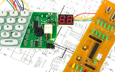
Microcontrollers facilitate a wide range of machine operations, from mobile phones to spacecraft, aircraft, and even life-support systems. Despite being small computers integrated into a single chip, they contain a processor core, memory, and programmable IO (input/output) peripherals. It is embedded inside a system where it controls a singular function by interpreting received data and enacting necessary actions.
Crafting unique microcontrollers for specific devices poses cost and time-inefficiency challenges. But with open-source software, a more vivid path for developing microcontroller hardware and software comes into view. Thousands of contributors across the world provide license-free codes, which are not only accessible but are also open for user modification depending on the desired function. On top of customization, identifying and fixing bugs comes in handy given the number of contributing developers.
An open-source microcontroller board, Arduino Uno has everything to support a microcontroller with a simple USB cable connection or an AC-to-DC adapter or battery. It has 14 digital IO pins among which are 6 PWM outputs, 6 analog inputs, and a 16MHz ceramic resonator. This board based on the ATmega328P also holds a power jack, a reset button, an ICSP header, and a USB connection. With Uno, tinkering is no issue—the worst-case scenario of replacing a broken chip only requires a few dollars. The use of UNO has reached the industries, utilizing it as the brain for their PLCs. In education and scientific projects, UNO boasts high standards and top-notch performance as a resource in capturing real-time information from sensors and triggering laboratory equipment.
Design
Processor and Memory
The main processor ATmega28P runs up to 20MHz, which is easily replaceable since it is not soldered. Most pins connect to the external headers but some are reserved for internal communication using the USB bridge coprocessor. It has a memory of 32KB, with the bootloader occupying 0.5KB, a 2KB SRAM, and 1KB of EEPROM, readable and writable with the EEPROM library.
Unlike preceding boards, UNO does not utilize the FTDI USB-to-serial driver chip but features ATmega16U2 programmed to be a USB-to-serial converter. It likewise manifests compatibility with Arduino 4 Relays Shield and Motor Shield Rev3.
Programming
Arduino UNO is programmable with Arduino’s IDE, CLI, and Web Editor. Preprogrammed with a bootloader, the ATmega328 allows the uploading of a new code without the need for an external hardware programmer. This bootloader can be bypassed via the ICSP header using the Arduino ISP. The Arduino repository holds the ATmega16U2, which can be loaded with a DFU bootloader activated by a resistor that pulls the 8U2/16U2 HWB line to the ground. For loading new firmware, Windows users can use Atmel's FLIP software and DFU programmer for Mac OS X and Linux. An ISP header connected with an external programmer can also overwrite the DFU bootloader.
Power
The automatic selection of power to the Arduino board can come from a USB connection or an external power supply (AC-to-DC adapter or battery). The board’s power jack requires a 2.1mm center-positive plug that can handle 6-20 volts of external supply. Although the recommended range sits at 7 to 12 volts.
Among the power pins, the Vin pin supplies voltage from an external power source. The 5V pin regulates a 5-volt output on the board from either the DC power jack (7 - 12V), the USB connector (5V), or the VIN pin (7-12V). The 3.3V pin on the other hand regulates a 3.3-volt output at a maximum current of 50mA. The GND pin stands for the ground pin, whereas the IOREF pin sets the operating voltage reference of the microcontroller.
For protection, Arduino UNO has a resettable polyfuse that trips when a 500mA current passes the USB port. This extra layer of protection saves the device from shorts and overcurrent.
Input and Output
UNO’s 14 digital pins work as input or output, using functions such as pinMode(), digitalWrite(), and digitalRead(). Each operates at 5 volts, providing or receiving 20mA for optimum operating conditions. Each pin has a disconnected-by-default internal pull-up resistor measuring 20-50k ohms. The current should not exceed 40mA to avoid permanent damage to the microcontroller. The 6 analog inputs, labeled A0 to A5, provide 10 bits of resolution each. The measure is from ground to 5 volts by default but can reach a higher upper end using the AREF pin and the function analogReference().
Some additional pins have specialized functions. Serial 0 (RX) and 1 (TX) receive and transmit TTL serial data. External interrupts 2 and 3 can trigger an interrupt on low values, rising or falling edges, or a total change of value. PWMs 3, 5, 6, 9, 10, and 11 provide an 8-bit PWM signal using the analogWrite() function. Supporting the SPI communication are SPIs 10 (SS), 11 (MOSI), 12 (MISO), and 13 (SCK), which run using the SPI library. Pin 13 is the LED pin, which signals when the pin has a high value and turns off when the pin value is low. Lastly, the A4 or SDA pin and A5 or SCL pin can support TWI communication via the Wire library.
Other pins on the board include the AREF pin, which sets the reference voltage of the analog inputs, and the RESET pin, which adds a reset button for shielding the microcontroller.
Communication
Arduino UNO has facilities that allow communication with a computer, another Arduino board, or other microcontrollers. It has the ATmega328 that supplies UART TTL serial communication via the digital pins 0 (RX) and 1 (TX). The ATmega16U2 provides serial communication via the USB, appearing as a com port to software. It uses the USB COM standard drivers and an additional .inf file for Windows devices.
The Arduino Software (IDE) has a monitor that sends simple textual data to and from the board. During data transmission via the USB-to-serial chip and USB connection, the RX and TX LEDs flash, but not for communications on pins 0 and 1. The SoftwareSerial library permits serial communication over any of the digital pins. ATmega328 likewise supports I2C and SPI communication, whereas the Arduino Software Wire library simplifies the use of the I2C bus.
Automatic (Software) Reset
Instead of a physical reset button, software run on a connected computer can prompt the reset of Arduino Uno. A 100 nF capacitor connects one of the hardware flow control lines (DTR) of the ATmega8U2/16U2 and the ATmega328 reset line. When the line takes low, the rest line drops for some time enough to reset the chip.
Arduino Software (IDE) has the capacity for uploading code using only the upload button found on the interface toolbar. This gives the bootloader a shorter timeout since lowering the DTR coordinates with the upload starts. The auto-reset can be disabled by cutting the trace contained in the Uno board and can be re-enabled by soldering the pads on the trace. Connecting a 110-ohm resistor between the 5V and reset line also disables the auto-reset feature.
References
Recommended Specs

Continue Reading
An In-depth Analysis of Features, Applications, and Selection Criteria for Embedded Systems Design. Discover the Advantages and Limitations of SPI, I2C, and UART for Efficient Data Exchange in Various Scenarios.

A deep dive into the UART protocol for digital design engineers, hardware engineers, and electronics engineering students. Learn how this common serial interface works, its configuration parameters, applications, and how it differs from other protocols.

Learn everything you need about the full adder circuit. From binary addition theory to low-power hardware implementations and modern ASIC/FPGA design flows, this technical article equips digital design engineers, hardware engineers with practical insights and current research trends.
