3 Phase Wire Color Code: Standards, Theory, and Practical Implementation
Three phase circuits deliver balanced power for industrial and high demand applications, but mismatched wires can cause equipment damage or safety hazards. These 3 phase wire color code schemes ensure correct installation, proper phase rotation, and compliance with electrical codes.

22 Dec, 2025. 13 minutes read
Key Takeaways
Standardized 3-phase wire color code schemes identify individual phases, the neutral conductor, and protective earth so engineers can wire systems safely and consistently.
The NEC (National Electrical Code) in the U.S. assigns different colors for 208/120 V and 480/277 V wye configurations; black, red, and blue are used for the 208 V phases, while brown, orange, and yellow identify 480 V phases. Orange also marks the high‑leg in four‑wire delta circuits.
Harmonized IEC 60445/UK standards use brown, black, and grey for phases L1–L3 and blue for neutral; older UK wiring used red, yellow and blue for the phase conductors.
Canada, China, Australia, Japan, and other regions follow variations of NEC or IEC rules; engineers must check local regulations before wiring.
Proper implementation includes verifying the color scheme on site, labeling conductors, de‑energizing circuits before work, and using phase rotation testers to ensure correct motor rotation.
Introduction
Three-phase supplies are critical in industrial setups, particularly for high-power requirements. Power distribution for large motors, commercial buildings, and data centers rarely relies on single‑phase supplies. This is because three‑phase alternating current provides smoother torque, higher power density, and greater efficiency. It divides power delivery into three sinusoidal waveforms spaced 120 degrees apart. Each phase must be correctly connected to maintain phase rotation and load balance, yet three identical conductors look identical if there is no identification.
A 3-phase wire color code assigns specific colors to each line conductor, the neutral, and the protective earth, thereby reducing the risk of misconnection. Standards such as the U.S. NEC, the Canadian Electrical Code (CEC), and the International IEC 60445 specify color codes for different voltage levels and system configurations.
This article explores the theory behind three‑phase systems, the need for 3-phase wire color code conventions, and compares the codes used in major jurisdictions. We will look at the practical guidance on selecting cables, wiring star (wye) and delta circuits, verifying phase sequence, and implementing proper labeling.
Fundamentals of Three‑Phase Power and Color Identification
Basic Concepts of Three-Phase Systems
Three‑phase systems deliver electrical power via three conductors carrying sinusoidal voltages offset by 120 degrees.
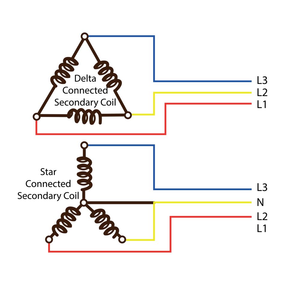
In a wye configuration, the ends of each phase are connected at a common neutral point.
In a delta configuration, the phases form a closed loop with no neutral.
The key advantages of a 3-phase system are:
Constant power transfer: The sum of instantaneous power delivered by three balanced phases is constant, avoiding torque pulsations in motors.
Reduced conductor size: For the same power, three‑phase systems use smaller conductors than equivalent single‑phase systems, reducing cost.
Dual voltage capability: By using a center‑tapped winding in wye or delta (four‑wire delta), both high‑voltage three‑phase and lower‑voltage single‑phase loads can be supplied.
Since the phase voltages and currents are symmetrical, incorrect connections may reverse rotation in motors or cause unbalanced loads. Therefore, color coding provides a visual method of identifying each phase conductor, so that installers can maintain the intended phase sequence.
Why Do We Need Wire Color Codes?
Color codes serve several purposes:
Maintenance and Troubleshooting: During repairs or upgrades, engineers must quickly recognize conductors. Uniform colors across systems allow technicians to trace circuits accurately.
Code Compliance: Electrical installations must conform to national and international standards. Using specified color codes ensures compliance with regulatory requirements and reduces liability.
Interoperability: Equipment manufactured in different regions may use different color schemes. Knowing multiple standards helps global companies integrate systems safely.
Safety and Hazard Prevention: Identifying hot, neutral and protective earth conductors prevents accidental contact with energized wires and reduces the risk of electric shock. Distinct colors for grounded neutral and ground wires help electricians quickly identify the conductors.
Suggested Reading: Electrical Testing: Comprehensive Guide for Engineering Professionals
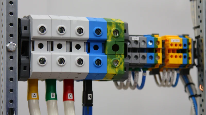
Color Identification and Phase Sequence
In three‑phase systems, the phase sequence—the order in which phases reach their peaks—affects motor rotation direction. Standard sequence is usually designated A–B–C or L1–L2–L3. If two phases are swapped, motors will run backward.
By assigning consistent colors to each phase conductor, installers can maintain the correct phase order from the service entrance to the load.
Phase rotation testers verify the sequence by measuring the time relationship of voltages. For critical systems such as data centers or medical equipment, verifying both color code and rotation before energizing is essential.
Regional 3‑Phase Wire Color Codes
A global uniformity of wire colors is desirable but it is not yet achieved. Different jurisdictions specify colors based on historical practice or local regulation. For engineers, it is therefore important to consult local standards for the use of correct scheme for the project. In this section, we will look at the regional wire color code schemes.
United States (NEC)
The U.S. National Electrical Code does not explicitly mandate specific colors for ungrounded (hot) conductors; however, local practice has established common conventions for safety and consistency.
The NEC emphasizes the identification of grounded neutral and equipment grounding conductors—neutral conductors must be white or gray and ground conductors must be green, green with yellow stripes or bare. For three‑phase circuits, the industry uses the following colors:
208/120 V (wye)
For commercial and residential 208 V three‑phase four‑wire wye systems (sometimes labeled 120/208 V), the following 3 phase wire color code is widely practiced:
Function | Color | Note |
Phase A (L1) | Black | Hot conductor carrying Phase 1 voltage |
Phase B (L2) | Red | Second-phase conductor |
Phase C (L3) | Blue | Third-phase conductor |
Neutral (N) | White | Grounded neutral conductor |
Ground (PE/EGC) | Green or bare | Protective earth; may have yellow stripe |
These colors mirror the single‑phase black (hot) and white (neutral) scheme but add red and blue for the extra phases. Using distinct colors helps technicians quickly identify each phase when connecting motors or distribution panels.
480/277 V (Wye)
Industrial facilities often use 480 V three‑phase power with a 277 V single‑phase branch. The recommended color scheme is brown for Phase A, orange for Phase B, yellow for Phase C, gray for neutral and green/bare for ground:
Function | Color | Note |
Phase A (L1) | Brown | First phase conductor |
Phase B (L2) | Orange | Second phase; also used to identify a high‑leg (see below) |
Phase C (L3) | Yellow | Third phase conductor |
Neutral (N) | Gray | Grounded neutral conductor |
Ground | Green, green/yellow, or bare | Protective earth conductor |
The NEC requires that the grounded (neutral) conductor in this voltage class be gray. The orange color indicates a “high leg” when a delta configuration supplies both three‑phase and single‑phase loads.
High‑leg Delta systems
Older or specialized systems may use a four‑wire delta transformer with a center‑tapped winding. The “high leg” has a voltage of 208 V to neutral, while the other two phases measure 120 V. The NEC stipulates that the high leg must be identified by orange or by other effective means. A common scheme is:
Blue for Phase 1 (A)
Orange for Phase 2 (high leg or stinger)
Black for Phase 3 (C)
White for neutral
Green for ground
Using the orange color for the stinger prevents accidental connection of single‑phase loads to the high leg, which would result in 208 V rather than 120 V.
Canadian Practice (CEC)
Canada’s wiring colors are similar to those used in the U.S., but some variations exist. For 208 V and 347/600 V multiphase circuits, the Canadian Electrical Code recommends red for Phase 1, black for Phase 2, blue for Phase 3, white or gray for neutral, and green/bare or green/yellow for the equipment grounding conductor.
For isolated 277/480 V systems, Canada uses orange, brown and yellow for the phases.
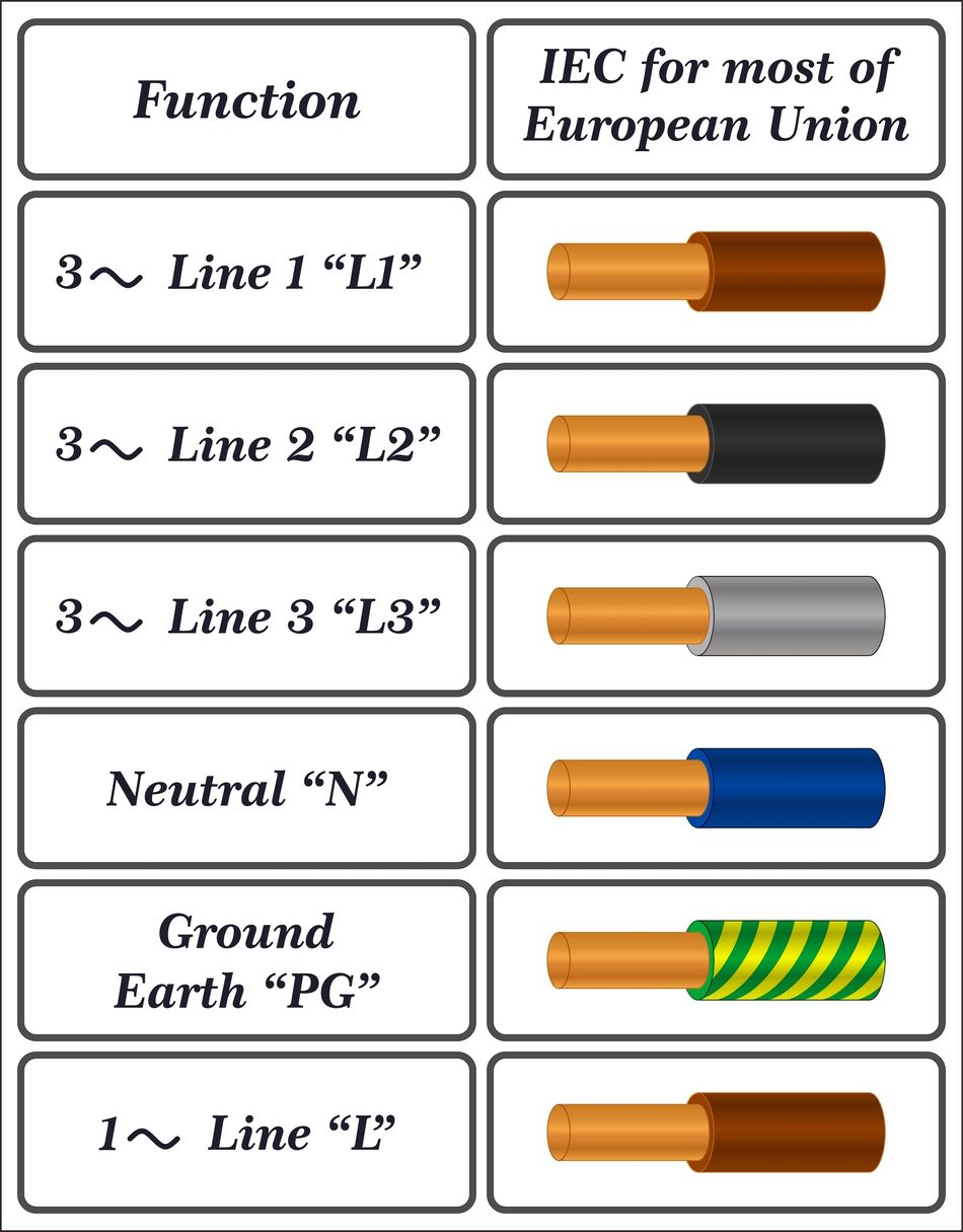
Europe/United Kingdom (IEC 60445)
The International Electrotechnical Commission’s IEC 60445:2021 standard specifies colors for conductors in AC and DC installations. The UK adopted the harmonized scheme in 2004, replacing the old British colors.
According to the IEC and UK wiring regulations, the 3-phase wire color code is:
Function | Color | Note |
Phase L1 | Brown | First line conductor |
Phase L2 | Black | Second line conductor |
Phase L3 | Grey | Third line conductor |
Neutral (N) | Light Blue | Grounded neutral conductor |
Earth (PE) | Green with yellow stripe | Protective earth conductor |

The old UK scheme used red, yellow and blue for phases and black for neutral; many older buildings still have these colors. When modifying such installations, it is mandatory to mark conductors clearly at interfaces.
China, Russia and Australia/New Zealand
China: The People’s Republic of China historically used yellow, green and red for phases and sky blue or black for neutral. Under the IEC harmonization, China now uses yellow (L1), green (L2), and red (L3) with light blue or black for neutral and green/yellow for earth. New installations should follow brown–black–grey for phases.
Russia: Russia previously used the Chinese colors but has largely adopted the IEC scheme with minor modifications; sometimes purple replaces grey.
Australia and New Zealand: These countries follow the AS/NZS 3000:2018 standard. For three‑phase circuits, they use red or brown for L1, white for L2, blue for L3, black or light blue for neutral, and green or green/yellow for earth.
Japan: Three‑phase 200 V supplies in Japan use black for L1, red for L2, white for L3, and green for earth.
India: The Bureau of Indian Standards (IS 11353:2023) specifies red, yellow, and blue for phases and black for neutral, consistent with older UK colors.
Comparison Table
The wiring color codes for 3-phase systems vary throughout the globe. Therefore, it is important to check the local regulations for specific requirements.
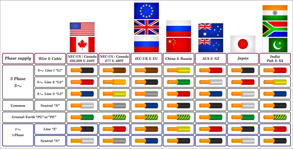
The following table summarizes common 3-phase wire color code schemes.
Region/Standard | L1 Color | L2 Color | L3 Color | Neutral | Earth |
USA (208 V wye) | Black | Red | Blue | White | Green/bare |
USA (480 V wye) | Brown | Orange | Yellow | Gray | Green/bare |
High‑leg delta | Blue | Orange (stinger) | Black | White | Green |
Canada (208/347 V) | Red | Black | Blue | White/Gray | Green/bare |
Canada (277/480 V isolated) | Orange | Brown | Yellow | White/Gray | Green/bare |
UK/EU (IEC 60445) | Brown | Black | Grey | Light Blue | Green/yellow |
UK (pre‑2004) | Red | Yellow | Blue | Black | Green |
China (historical) | Yellow | Green | Red | Light Blue/Black | Green/yellow |
Australia/New Zealand | Red/Brown | White | Blue | Black/Light Blue | Green/green‑yellow |
Japan | Black | Red | White | White (two‑line system) | Green |
India (IS 11353) | Red | Yellow | Blue | Black | Green/yellow |
Practical Implementation of 3‑Phase Wiring
Planning and design considerations
When designing three‑phase power distribution, engineers should consider voltage level, load type, conductor size and protection. Key steps include:
Determine the supply configuration: Identify whether the service is 208 V wye, 480 V wye, high‑leg delta, 415 V three‑phase, or another arrangement. This determines the appropriate color code and cable rating.
Select cable insulation and gauge: Choose conductors rated for the system voltage and current. Use ampacity tables and derating factors for ambient temperature and conduit fill. For large motors or VFDs, minimize voltage drop by selecting larger conductors.
Identify phases on drawings: Use the chosen 3 phase wire color code in schematics and labels. Document phase rotations and numbering to ensure uniformity across the project.
Plan for neutral and ground conductors: Wye systems require a neutral conductor sized according to the maximum unbalanced load. Always include a grounding conductor of appropriate size and color.
Suggested Reading: What Is Ground in a Circuit? Understanding Grounding Concepts and Implementations
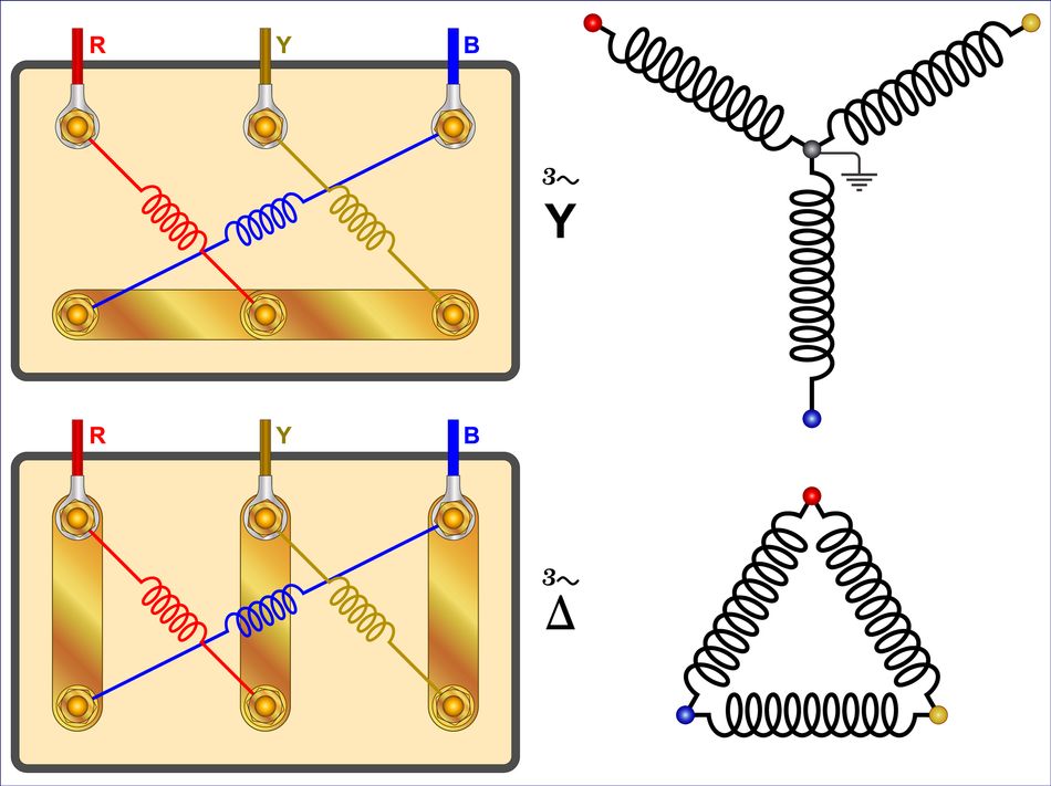
Star (Wye) and Delta connections
Three‑phase systems may connect loads or sources in star or delta. Understanding the wiring helps to apply the correct color code.
Star (wye): Each phase conductor connects to one end of a winding; the other ends join at a neutral point. The phase voltage (line–neutral) is lower than the line voltage (phase–phase) by √3. Use the neutral conductor color for the common point and assign each phase color to the individual line wires.
Delta: The phases connect end to end in a closed loop. There is no neutral unless a center tap is provided (as in high‑leg delta). Connect the three-phase conductors in sequence (L1 to L2, L2 to L3, L3 to L1). Use the appropriate colors for each side of the delta loop. For high‑leg delta, use orange to mark the phase with the higher line–neutral voltage.
Wiring Procedure and Safety Steps
Verify de‑energization: Turn off the power at the circuit breaker or service disconnect and test with a calibrated voltage tester before touching conductors.
Inspect existing colors: Many older systems use obsolete colors. Use a multimeter to identify phases and mark them using colored tape or labels according to the updated code.
Route and terminate cables: Route phase conductors to the appropriate terminals (L1, L2, L3). Use wire markers or heat‑shrink tubing to label each conductor with both its color code and phase designation.
Connect neutral and ground: Terminate the neutral conductor at the neutral bus bar and the ground conductor at the grounding bar. Ensure continuity and correct bonding to the service equipment.
Check phase rotation: Use a phase rotation meter to confirm the sequence (ABC). If the motor runs backward, swap any two phase conductors at the load end.
Document the installation: Update circuit diagrams, labeling and maintenance records to reflect the 3 phase wire color code used. Provide signage at panelboards when different systems or high‑leg phases are present.
Follow lockout/tagout procedures: Label circuits and apply locks to prevent accidental energization. Use OSHA‑compliant tags and locks for each worker on site.
Recommended Reading: A crash course on occupational health & safety: safer workplaces for improved productivity
Special Considerations for Instrumentation and Control
Digital design and hardware engineers often interface control electronics with three‑phase power systems. When integrating sensors, controllers or data acquisition units:
Use isolation: Employ opto‑isolators or potential transformers to measure line voltages without exposing low‑voltage electronics to high energy.
Adhere to low‑voltage color codes: Within control panels, follow the IEC or local codes for auxiliary circuits (e.g., brown for 24 V DC positive, blue for 0 V, etc.). Document any deviations for maintenance personnel.
Label terminal blocks: For modular designs, mark terminals with both phase names and color codes to reduce confusion during field wiring.
Shield and twist control wiring: Three‑phase power cables can radiate electromagnetic noise. Use shielded instrumentation cables and maintain separation from power conductors to reduce interference.
Suggested Reading: EMI Shielding: Protecting Electronic Devices in a Noisy World
Choosing the Right Cable and Labeling System
Proper materials and labeling contribute to safe three‑phase installations. Consider the following:
Cable type: Use multi‑core cables with color‑coded insulation to minimize installation errors. If only single‑color insulation is available, apply colored tape or heat‑shrink tubing at both ends.
Temperature and environment: Choose insulation materials (PVC, XLPE, silicone) rated for the operating temperature. For harsh environments, use oil‑resistant or UV‑resistant sheathing.
Labeling and markers: Use durable labels that can withstand heat and chemicals.
Dealing with Mixed Color Codes in Retrofits
Upgrading equipment in older buildings often means encountering obsolete color schemes. Use the following approach:
Identify the existing code: Determine whether the installation uses old UK colors (red/yellow/blue) or other regional schemes.
Mark conductors: At interfaces where old colors meet new colors, mark each conductor with its function (L1, L2, L3, N, PE). Use colored sleeving or tags to avoid confusion.
Document and inform: Provide a transition diagram showing the old and new colors. Instruct maintenance personnel to verify color markings with testers before connecting loads.
Theoretical Considerations for Engineers
Voltage Relationships in three‑phase systems
Understanding voltage relationships helps engineers choose appropriate insulation and phasing. In a balanced star (wye) system with line‑to‑neutral voltage Vphase and line‑to‑line voltage Vline the relation is:

For example, a 120 V phase voltage yields a line voltage of 208 V approx..
On the other hand, the phase voltage in delta configuration equals the line voltage because each load is connected directly between two phases.
Engineers must ensure that motors and equipment are rated for the correct voltage class and that the 3 phase wire color code corresponds to the supply.
Phase Angle and Vector diagrams
Phasor diagrams illustrate the 120° separation between phases. Maintaining this separation ensures balanced currents. If one phase conductor is swapped, the rotation becomes reversed. Color coding helps avoid such mistakes; however, engineers still need to verify rotation with instruments.
Symmetry, Harmonics and EMC
Balanced three‑phase systems produce zero net neutral current when loads are identical. However, non‑linear loads like rectifiers generate triplen harmonics (3rd, 9th, etc.) that add in the neutral conductor. When high harmonic content is expected, size the neutral conductor appropriately and use separate neutrals for each branch.
Good design also includes proper grounding and shielding to mitigate electromagnetic interference. Use twisted pair control wires and ground referenced shielding to protect sensitive digital circuits.
Standards evolution and future trends
The evolution of color codes reflects global efforts to harmonize electrical standards. The UK’s 2004 adoption of brown‑black‑grey colors aligned with IEC 60445, facilitating trade within the EU. The latest edition IEC 60445:2021 clarifies conductor identification and permits more colors for control circuits.
Meanwhile, the NEC continues to recommend—but not mandate—hot conductor colors, leaving flexibility for industry practice. As renewable energy, microgrids, and electric vehicles continue to thrive, cross‑border installations will become more common. Therefore, electrical engineers should stay informed about new editions of standards and national deviations.
Suggested Reading: Whats The Difference Between UL And IEC Standards?
Conclusion
Three‑phase power systems underpin modern industry, data centers and renewable energy installations. Proper identification of conductors using a recognized 3 phase wire color code promotes safety, simplifies troubleshooting and ensures compliance with national codes. The U.S. NEC conventionally uses black/red/blue for 208 V and brown/orange/yellow for 480 V systems with white or gray neutrals and green grounds. The IEC harmonized code adopted in the UK and many countries uses brown, black and grey phases with light blue neutrals. Engineers must be aware of regional differences, older color schemes and special cases like high‑leg delta circuits, where orange identifies the high leg.
Beyond memorizing tables, best practices include verifying the supply configuration, labeling conductors, de‑energizing circuits before work, checking phase rotation, selecting appropriate cables, and maintaining documentation. Digital design engineers should also consider isolation and EMC when interfacing control circuits with three‑phase power. By understanding the theory and practical implementation of 3 phase wire color code schemes, engineers and students can design and maintain safe, reliable systems that meet global standards.
FAQs
1. Why do 208 V and 480 V systems use different color codes in the United States?
The NEC does not mandate specific colors for hot conductors, but industry practice uses distinct colors to distinguish voltage classes. Black, red and blue identify the lower 208/120 V system, while brown, orange and yellow denote the higher 480/277 V system. Using separate schemes helps electricians avoid mixing circuits of different voltages, which could damage equipment.
2. What is the purpose of the orange “high leg” in delta systems?
In four‑wire delta supplies, one transformer winding is center‑tapped to provide a 120 V neutral. The phase opposite the center tap has a voltage of 208 V to neutral. This “high leg” must not be used for 120 V loads. The NEC requires it to be identified with orange so that electricians do not mistakenly connect it to 120 V circuits.
3. How should I handle installations with older UK colors?
Many buildings wired before 2004 use red, yellow and blue for phases and black for neutral. When making additions or alterations, mark both the old and new conductors at the interface using labels or colored sleeves. Table 7A in the UK guide shows the correspondence between old and new colors. Always verify each conductor with a tester before connecting.
4. Are there differences between 50 Hz and 60 Hz systems in color codes?
Frequency (50 Hz or 60 Hz) does not affect color codes. The color scheme depends on regional standards and voltage class. For example, Europe uses brown/black/grey regardless of 50 Hz frequency, while the U.S. uses black/red/blue for 60 Hz 208 V systems.
5. How can I verify the correct phase sequence?
Use a phase rotation meter on the three phase conductors. Connect the meter leads to L1, L2 and L3 and read the displayed rotation (usually indicated as ABC or CBA). If the sequence is incorrect, swap any two phase conductors at the load. Always verify phase rotation before starting motors, especially when retrofitting or after service.
6. Do color codes apply to DC systems?
Yes. The NEC and IEC specify separate color schemes for DC circuits. In the U.S., red usually denotes the positive conductor, black the negative, and white or gray the grounded neutral. The IEC uses brown, blue and grey for DC positive, mid‑wire and negative. When designing mixed AC/DC systems, clearly separate the wiring and color identification to prevent confusion.
7. Where can I find official color code standards?
The NEC is published by the National Fire Protection Association (NFPA 70). The IEC standard for identification of conductors is IEC 60445. In the UK, the Institution of Engineering and Technology (IET) publishes BS 7671 (Wiring Regulations). Local building authorities often provide guidance based on these documents. Always consult the latest edition and any national deviations before starting an installation.
References
"Wiring color codes - NEC electrical standards & 3-phase," BradyID, available at: https://www.bradyid.com/resources/wiring-color-codes
"3-phase wire color code: A complete guide," TOT Cables, available at: https://totcables.com/news/3-phase-wire-color-code-a-complete-guide/.
"Four wire delta circuits," Continental Control Systems, available at: https://ctlsys.com/support/four_wire_delta_circuits/.
"Wiring colour codes: An introductory guide to electrical wire identification," Newark, available at: https://www.newark.com/wiring-color-codes-an-introductory-guide-to-electrical-wire-identification-trc-sg
"Electrical wiring color codes: NEC & IEC," Electrical Technology, available at: https://www.electricaltechnology.org/2020/07/electrical-wiring-color-codes-nec-iec.html.
"Harmonised cable core colours," CSE Distributors, available at: https://www.cse-distributors.co.uk/cable/technical-tables-useful-info/harmonised-cable-core-colours.html