Verilog vs VHDL: A Comprehensive Comparison
Unveiling the Duel of Digital Design - A Comprehensive Exploration of History, Syntax, and Applications of the two popular hardware description languages

08 Apr, 2024. 16 minutes read
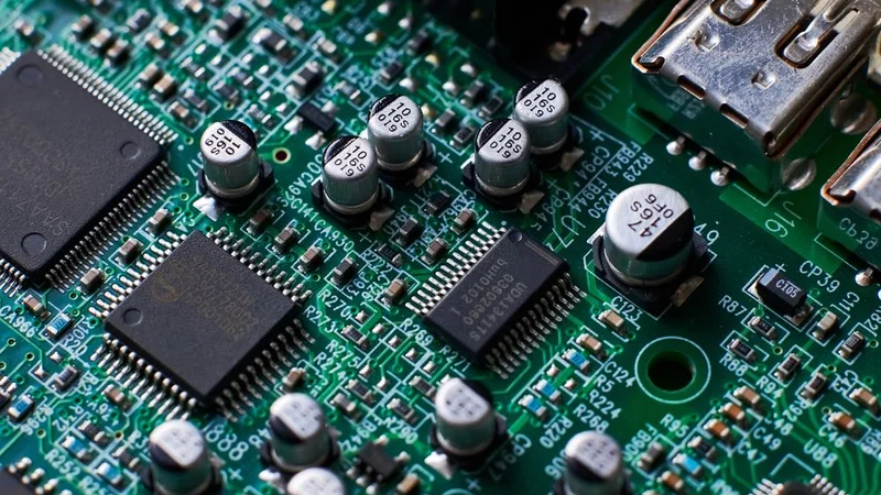
Fig 1 - Printed Circuit Board Chips and Radio Components
Introduction
Verilog and VHDL are two primary hardware description languages (HDLs) engineers and designers use to model, simulate, and synthesize digital systems. These languages are crucial in developing integrated circuits (ICs), field-programmable gate arrays (FPGAs), and other digital hardware.
While both languages serve similar purposes, they have distinct syntax, design methodologies, and features that can influence the choice between them for a specific project. This article aims to provide a comprehensive Verilog and VHDL comparison, delving into their history, syntax, design methodologies, features, tools, industry adoption, and applications.
Further Reading: FPGA Design: A Comprehensive Guide to Mastering Field-Programmable Gate Arrays
What are Hardware Description Languages?
Hardware Description Language (HDL) describes a digital circuit's behavioral or structural orientation. These languages can simulate digital circuits for the evaluation of circuit responses before fabrication. Moreover, both Verilog and VHDL are used to formulate digital circuits to produce ASIC or FPGA-based systems.
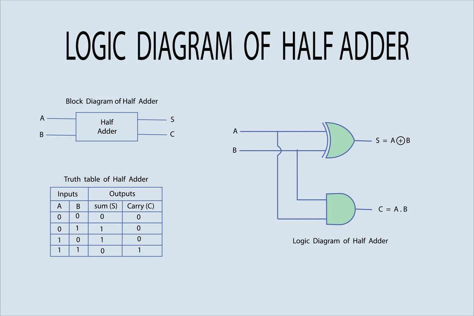
For instance, consider the following example, where an HDL code produces a simplistic digital circuit design.
module HalfAdder (
    input A, // First input bit
    input B, // Second input bit
    output Sum, // Sum output
    output Cout // Carry output
);
assign Sum = A ^ B; // XOR operation for sum
assign Cout = A & B; // AND operation for carry output
endmodule
The trend for HDLs started in the 1980s as digital design companies explored the possibilities of languages that could shape digital circuits. While several HDLs like Java HDL (JHDL), Cypress SemiConductor Corporation's Active HHDL, etc., Verilog and VHDL have been widely accepted and endorsed by IEEE (Institute of Electrical and Electronics Engineers) standards.
Historical Development of the Two Languages
History of Verilog
Verilog was initially developed in the late 1980s by Gateway Design Automation as a proprietary language for simulating and verifying digital circuits. It was one of the first hardware description languages developed from 1983 to 1984. The language quickly gained popularity due to its simplicity and ease of use. Here is a quick summary of its development:
1990: Cadence Design Systems acquired Gateway Design Automation and subsequently released the Verilog language as an open standard. This decision spurred the growth of the Verilog user community and the development of third-party tools for simulation and synthesis.
1995: The first official standard for Verilog, known as IEEE Standard 1364-1995, was published. This standard introduced several enhancements to the language, including support for behavioral modeling and testbenches.
2001: IEEE released an updated standard, IEEE 1364-2001, which expanded the language's capabilities by adding constructs for representing complex digital systems and improving support for verification.
2005: IEEE merged the Verilog standard with SystemVerilog, a Verilog superset incorporating advanced features for system-level modeling, verification, and design reuse. The combined standard, IEEE 1800, has since become the de facto standard for digital design using Verilog. Today, Verilog is widely used in the semiconductor industry for designing application-specific integrated circuits (ASICs), FPGAs, and other digital systems.
History of VHDL
VHDL, which stands for VHSIC (Very High-Speed Integrated Circuit) Hardware Description Language, was developed in the early 1980s by the U.S. Department of Defense (DoD) as part of the VHSIC program. The program's primary goal was to create a standardized language for the design and verification of digital systems, particularly for military applications. VHDL was designed to be a powerful, flexible, and portable language that could accurately represent complex digital systems at various levels of abstraction.
1987: IEEE adopted VHDL as an official standard, IEEE 1076. This standardization helped promote VHDL's widespread adoption in both military and commercial sectors.
1993: A notable revision IEEE 1076-1993 was approved, which introduced support for synthesis and test benches
2008: IEEE 1076-2008 was approved, which added improved modeling and verification features.
2019: IEEE 1076-2019 was approved. The standard featured enhancements in synthesis, verification, and design modeling, and introduced fixed-point arithmetic support.
Today, VHDL is widely used for designing ASICs, FPGAs, and other digital systems, with a robust ecosystem of simulation, synthesis, and verification tools available to support the design process.
Language Syntax and Structure
Verilog Syntax
Verilog's syntax is based on the C programming language, making it familiar and accessible for those with a background in C or C-like languages. The basic building blocks of Verilog are modules, which represent individual components of a digital system. A module can contain inputs, outputs, internal signals, and instances of other modules, allowing for hierarchical design.
Data Types in Verilog
In Verilog, data types include:
Wire - represents physical connections between components
reg - Stores values in registers
Integer
Real
The integer and real data types are used for arithmetic operations and modeling.
Verilog supports various operators, such as arithmetic, relational, logical, and bitwise operators. These operators enable designers to perform calculations, comparisons, and manipulations of data within the language.
A key feature of Verilog syntax is the use of procedural and continuous assignments, that are used to:
Describe the behavior of a digital system
Model the combinational logic and relationship between various signals.
Here's an example of a simple Verilog module that implements a 2-input AND gate:
module and_gate (
  input wire a,
  input wire b,
  output wire y
);
  assign y = a & b;
endmodule
In this example, the module named "and_gate" has two input wires, "a" and "b," and one output wire, "y." The continuous assignment statement "assign y = a & b;" defines the relationship between the input and output signals, implementing the AND gate functionality.
VHDL Syntax
VHDL syntax is inspired by the Ada programming language and is more verbose compared to Verilog. The primary building blocks of VHDL are entities and architectures, which together define the behavior and structure of a digital system. An entity describes the interface of a component, including its input and output ports, while an architecture defines the internal behavior and interconnections of the component.
VHDL Data Types
VHDL has a rich set of data types, including:
bit
bit_vector
integer
Real
enumerated types.
The bit and bit_vector data types represent binary values and arrays of binary values, respectively. Integer and real data types are used for arithmetic operations and modeling purposes, while enumerated types allow designers to define custom data types with a finite set of values.
VHDL supports a wide range of operators, including arithmetic, relational, logical, and bitwise operators. These operators enable designers to perform calculations, comparisons, and data manipulations within the language.
In VHDL, concurrent and sequential statements describe the behavior of digital systems and the relation between signals in a digital system. Here's an example of a simple VHDL entity and architecture that implements a 2-input AND gate:
entity and_gate is
  port (
    a : in bit;
    b : in bit;
    y : out bit
  );
end entity and_gate;
architecture behavior of and_gate is
begin
  y <= a and b;
end architecture behavior;
In this example, the entity "and_gate" defines the interface with two input ports, "a" and "b," and one output port, "y." The architecture "behavior" describes the internal behavior of the AND gate using a concurrent signal assignment statement "y <= a and b;", which defines the relationship between the input and output signals.
Digital Design Methodologies
Design methodology refers to designing, implementing, and verifying digital electronic systems. It encompasses a set of principles, practices, and techniques engineers follow to ensure that the final digital circuit meets its intended functionality, performance, and reliability requirements. Some of the critical aspects and steps commonly involved in a digital circuit design methodology include:
Specification and Requirements Analysis - understanding the requirements and specifications of the digital circuit.
High-Level Design - Create a high-level or architectural design that defines the overall structure and functionality of the digital system.
Functional Verification - Verification that the high-level design meets the specified requirements. It involves simulations and modeling to ensure that the system functions as intended.
RTL (Register-Transfer Level) Design - Creating a detailed RTL design using a hardware description language (HDL) like Verilog or VHDL.
Further Reading: RTL Design: A Comprehensive Guide to Unlocking the Power of Register-Transfer Level Design
Synthesis - Using synthesis tools to convert the RTL description into a gate-level netlist.
Gate-Level Simulation - Simulating gate-level netlist to verify that it meets functional and timing requirements after synthesis.
Physical Design - Perform physical design tasks, including floor planning, placement, and routing, to generate a physical representation of the circuit. This step is crucial for manufacturing the chip.
Timing Analysis - Analyzing the circuit for timing violations and ensuring the design meets the specified timing constraints.
Functional Verification (again) - Conducting thorough verification tests to ensure that the synthesized and physically designed circuit behaves correctly.
Design for Testability (DFT) - Implementing testability features to facilitate manufacturing testing, such as built-in self-test (BIST) or scan chains.
Manufacturing - Sending the final design to a fabrication facility (foundry) for chip manufacturing.
Testing - Testing manufactured chips to identify any defects or manufacturing errors.
Debugging and Validation - Debugging any issues that arise during testing and validating that the chips meet the original specifications.
Documentation - Maintaining comprehensive documentation throughout the design process, including design specifications, test plans, and design reviews.
Post-Silicon Debug - If the design is implemented in an FPGA or ASIC, post-silicon validation may be necessary to ensure the design works correctly in the physical device.
Iteration and Optimization - Iterating on the design as needed to address any issues, optimizing performance, or make improvements based on feedback or changing requirements.
Verilog Design Methodology
Verilog design methodology uses the concept of modules and hierarchy. Modules are the fundamental building blocks of a digital system, encapsulating functionality and interconnections. A module can instantiate other modules, creating a hierarchical design that promotes modularity, reusability, and ease of understanding.
Designers typically start by creating a top-level module representing the entire digital system. This module instantiates and interconnects lower-level modules, which may instantiate even lower-level modules.
This hierarchical approach allows designers to break down complex systems into manageable, reusable components.
Testbenches in Verilog
Testbenches are crucial in the Verilog design methodology. A testbench is a separate module that instantiates the design under test (DUT) and applies input stimuli to verify its functionality. Testbenches can be written using behavioral Verilog, which allows designers to describe the desired behavior of the system without specifying its implementation details. This abstraction enables efficient verification of the design's functionality and performance under various conditions.
Simulation and Synthesis Tools
Simulation tools, like ModelSim and VCS, enable designers to execute and debug their Verilog code, providing insights into the behavior of the digital system under different scenarios.
Synthesis tools, such as Synopsys Design Compiler and Xilinx Vivado, convert the Verilog code into a gate-level netlist or an FPGA bitstream, which can then be used for implementation on an ASIC or FPGA, respectively.
These tools also perform optimizations to meet design constraints, such as timing, area, and power requirements.
VHDL Design Methodology
The VHDL design methodology focuses on entities, architectures, and hierarchy. Entities define the interfaces of components, while architectures describe their internal behavior and interconnections. Like Verilog, VHDL promotes a hierarchical design approach, allowing designers to break down complex systems into smaller, reusable components.
In a typical VHDL design process, designers create a top-level entity representing the entire digital system. This entity instantiates and interconnects lower-level entities, which may further instantiate even lower-level entities. This hierarchical structure enables modularity and reusability, making managing and understanding complex designs easier.
Testbenches in VHDL
In VHDL, Testbenches can be written using behavioral VHDL, allowing designers to describe the desired behavior of the system without specifying its implementation details. This abstraction efficiently verifies the design's functionality and performance under various conditions.
Essential Language Features
Verilog Features
Verilog offers several vital features enabling designers to effectively model and verify digital systems. Some of the most notable features include.
Procedural Assignments - used within 'always' blocks to describe the behavior of a digital system in response to changes in input signals or internal states. These assignments allow designers to model sequential logic, such as flip-flops and state machines, using familiar programming constructs like if-else statements and loops.
Continuous assignments - used to model combinational logic and define the relationship between input and output signals. These assignments are evaluated continuously, ensuring that the output signals are always up-to-date concerning their input signals.
Gate-level modeling - Verilog supports gate-level modeling, which allows designers to describe digital systems using primitive gates, such as AND, OR, and NOT gates. This feature enables designers to model and simulate digital systems at a low level of abstraction, providing insights into the underlying hardware implementation.
User-defined primitives (UDPs)- Verilog allows designers to create user-defined primitives, custom gate-level components that can be instantiated and used in a design. UDPs enable designers to model complex or specialized logic elements that may not be available as built-in primitives.
Behavioral modeling - Verilog supports behavioral modeling, which allows designers to describe the desired behavior of a digital system without specifying its implementation details. This abstraction enables efficient verification of the design's functionality and performance under various conditions.
For example, consider a simple 4-bit counter implemented in Verilog:
module counter (
  input wire clk,
  input wire reset,
  output reg [3:0] count
);
always @(posedge clk or posedge reset) begin
  if (reset) begin
    count <= 4'b0000;
  end else begin
    count <= count + 4'b0001;
  end
end
endmodule
In this example, the counter uses procedural assignments within an always block to model the sequential behavior of the counter. The count signal is updated on the rising edge of the clock, and the counter is reset when the reset signal is asserted. This demonstrates the use of Verilog features such as procedural assignments, behavioral modeling, and data types like reg and wire.
VHDL Features
VHDL offers a rich set of features that model, simulate, and verify digital systems effectively. Some of the most notable features include:
Process Statements - used to describe the behavior of a digital system in a sequential manner, similar to traditional programming languages. These statements are executed within a ‘process’ block, which is sensitive to specific signals or events. Process statements allow designers to model sequential logic, such as flip-flops and state machines, using familiar programming constructs like if-else statements and loops.
Concurrent statements - Used for signal assignments and component instantiations, describe the relationships between signals and components that occur simultaneously. These statements enable designers to model combinational logic and define the interconnections between components in a digital system.
Component Instantiation - allows designers to create reusable components and instantiate them within a higher-level architecture. This feature promotes modularity and reusability, making it easier to manage and understand complex designs.
Generics and Configurations - enable designers to create parameterized components and customize their behavior or structure. Generics allow designers to define parameters for a component, while configurations enable designers to specify the mapping between entities and architectures, as well as the values of generics for specific instances.
Package and Libraries - allow designers to organize and reuse code across multiple projects. Packages can contain declarations of data types, subprograms, and components, while libraries are used to store and manage packages and design units.
For example, consider a simple 4-bit counter implemented in VHDL:
library ieee;
use ieee.std_logic_1164.all;
use ieee.numeric_std.all;
entity counter is
  port (
    clk : in std_logic;
    reset : in std_logic;
    count : out unsigned(3 downto 0)
  );
end entity counter;
architecture behavior of counter is
  signal count_internal : unsigned(3 downto 0);
begin
  process (clk, reset) begin
    if reset = '1' then
      count_internal <= (others => '0');
    elsif rising_edge(clk) then
      count_internal <= count_internal + 1;
    end if;
  end process;
 count <= count_internal;
end architecture behavior;
In this example, the counter uses a process statement to model the sequential behavior of the counter. The count_internal signal is updated on the rising edge of the clock, and the counter is reset when the reset signal is asserted. This demonstrates the use of VHDL features such as process statements, concurrent statements, and data types like std_logic and unsigned.
Simulation and Synthesis Tools
When it comes to design and synthesis tools, most of the popular applications provides support for both VHDL and Verilog. Some of the most widely used tools include:
ModelSim
ModelSim is a high-performance digital simulation tool developed by Mentor Graphics (now part of Siemens EDA). It supports both Verilog and VHDL languages and offers advanced debugging features, such as waveform viewing, source code stepping, and breakpoint setting.
There are advanced debugging features, such as waveform viewing, source code stepping, and breakpoint setting. It is widely used in the industry for functional verification and timing analysis of digital designs.
VCS (Verilog Compiled Simulator)
VCS, developed by Synopsys, is a high-performance Verilog simulator that provides fast simulation and advanced debugging capabilities.
VCS supports both Verilog and SystemVerilog languages and offers features like waveform viewing, source code stepping, and breakpoint setting. It is widely used for functional verification and performance analysis of digital designs.
Synopsys Design Compiler
Design Compiler is a synthesis tool developed by Synopsys that translates Verilog code into a gate-level netlist for ASIC implementation.
It performs optimizations for timing, area, and power, ensuring that the synthesized design meets the specified constraints. Design Compiler is widely used in the industry for ASIC synthesis and optimization.
GHDL
GHDL is an open-source VHDL simulator that provides a fast and efficient way to simulate and verify VHDL designs. It supports the IEEE 1076 standard and offers basic debugging capabilities, such as waveform viewing and source code stepping.
It is a popular choice for designers looking for a free and open-source alternative to commercial VHDL simulators.
Xilinx Vivado
Vivado is a comprehensive design suite developed by Xilinx for FPGA design, synthesis, and implementation. It supports both Verilog and VHDL languages and offers advanced features like high-level synthesis, IP integration, and design optimization. Vivado is widely used for FPGA design and implementation, targeting Xilinx FPGA devices.
Industry Adoption and Applications
Verilog Adoption
Verilog has been widely adopted in various industries due to its simplicity, ease of use, and compatibility with the C programming language. Some of the key industries and applications where Verilog is commonly used include:
Semiconductor industry
Verilog is extensively used in the design and verification of application-specific integrated circuits (ASICs) and field-programmable gate arrays (FPGAs). Its syntax and features make it suitable for modeling complex digital systems at different levels of abstraction, from gate-level to behavioral-level descriptions.
Further Reading: What is an ASIC: A Comprehensive Guide to Understanding Application-Specific Integrated Circuits
Telecommunications
In the telecommunications industry, Verilog is used to design and verify digital signal processing (DSP) components, such as filters, modulators, and demodulators. These components are critical for the efficient transmission and reception of data in modern communication systems.
Consumer Electronics
Verilog is employed in the design of various consumer electronic devices, such as smartphones, tablets, and gaming consoles. It is used to develop custom ICs and FPGAs that provide the necessary processing power, graphics capabilities, and connectivity features for these devices.
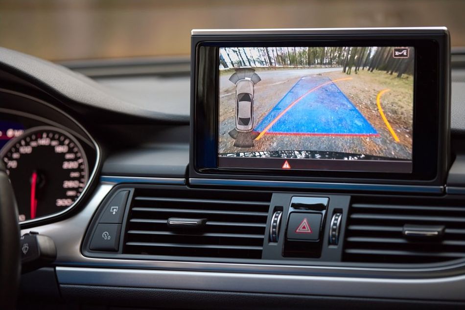
Automotive Industry
With the increasing demand for advanced driver assistance systems (ADAS) and autonomous vehicles, Verilog has found applications in the automotive industry. It is used to design and verify digital systems responsible for sensor processing, decision-making, and control in modern vehicles.
One notable example of a successful project that utilized Verilog is the design of the RISC-V open-source processor architecture. RISC-V was developed at the University of California, Berkeley, and has gained significant attention due to its flexibility, modularity, and open-source nature. Verilog was used to describe the RTL (register-transfer level) design of the RISC-V processor, enabling its implementation on various ASIC and FPGA platforms.
Another notable application of Verilog HDL comes in the form of a lane changing prediction system that provides assistance to the driver for changing lanes on a straight road. The system uses FPGA Zybo 700 to analyze driver performance and predict directions using eye and face detection.
VHDL Adoption
VHDL has been widely adopted in various industries due to its strong typing, modularity, and support for concurrent design. Some of the key industries and applications where VHDL is commonly used include:
Aerospace and Defense
VHDL is extensively used in the aerospace and defence industries for design and verification of safety-critical digital systems, such as avionics, radar, and missile guidance systems. Its strong typing and formal semantics make it well-suited for large-scale projects with stringent reliability and safety requirements.
As FPGA designs have profound applications in unmanned systems too, VHDL becomes a primary component in the design of FPGA-based aircraft and unmanned vehicles for enhancing their security, especially for long-term deployments.
Machine Learning and AI Acceleration
FPGAs are constantly being adopted in machine learning and AI as they are capable of parallel processing. Hence, specially designed libraries allow engineers to deploy accelerated AI models with unmatchable performance and efficiency, enabling AI-powered products and services for regular consumers.
Industrial automation
In the industrial automation sector, VHDL is used to design and verify digital systems responsible for process control, monitoring, and data acquisition. These systems are critical for ensuring the efficient operation and safety of industrial processes and equipment.
One notable example of a successful project that uses VHDL is the design of the LEON processor, an open-source, fault-tolerant, and radiation-hardened processor based on the SPARC architecture.
Source: SA - LEON
Developed by the European Space Agency (ESA), the LEON processor has been used in various space missions, such as the Mars Express and the BepiColombo mission to Mercury. VHDL was used to describe the RTL (register-transfer level) design of the LEON processor, enabling its implementation on various ASIC and FPGA platforms with the required fault-tolerance and radiation-hardening features.
Choosing Between Verilog and VHDL
When deciding between Verilog and VHDL for a project, several factors should be considered to ensure the most suitable language is chosen. Some of the key factors include:
Design Complexity
Verilog's C-like syntax and simpler constructs may be more suitable for smaller projects or designers with a background in C programming. On the other hand, VHDL's strong typing and support for concurrent design make it well-suited for large-scale projects and safety-critical applications.
Industry and application
Verilog is widely used in the semiconductor industry, while VHDL is more prevalent in the aerospace and defense sectors.
Also, familiarity with the language commonly used in a particular industry can be beneficial for designers seeking employment or collaboration opportunities.
Team Expertise
The expertise and experience of the design team can play a significant role in the choice between Verilog and VHDL. If the team is already familiar with one language, it may be more efficient to continue using that language to leverage existing knowledge and skills.
Design Reuse and IP integration
The availability of reusable design components or intellectual property (IP) cores can also influence the choice between Verilog and VHDL. Hence, designers must consider the availability of IP cores and libraries in their target language and choose the language that offers the best resources for their specific project requirements.
Conclusion
This article provides a comprehensive comparison of Verilog and VHDL, two prominent hardware description languages used in digital system design. We have explored their history, syntax, design methodologies, features, simulation and synthesis tools, and industry adoption.
By understanding the differences and similarities between these languages, designers can make informed decisions when choosing the right language for their projects and gain insights into the intricacies of digital hardware design.
Frequently Asked Questions (FAQs)
1. Can Verilog and VHDL be used together in a single project?
Yes, it is possible to use both Verilog and VHDL in a single project by employing mixed-language simulation and synthesis tools. These tools can handle designs written in both languages, allowing designers to leverage the strengths of each language and reuse existing IP cores or libraries.
2. Which language is easier to learn, Verilog or VHDL?
The ease of learning Verilog or VHDL depends on the individual's background and preferences. Verilog's syntax is similar to C, making it easier for those with a background in C or C-like languages. VHDL, on the other hand, has a more verbose syntax and strong typing, which some designers may find more structured and easier to understand.
3. Are there any open-source tools available for Verilog and VHDL?
Yes, there are several open-source tools available for both Verilog and VHDL, such as Icarus Verilog and GHDL for simulation, and Yosys for synthesis. These tools provide an alternative to commercial tools and can be used for learning, experimentation, or even production designs.
4. How do I choose between an ASIC and an FPGA for my digital design project?
The choice between an ASIC and an FPGA depends on factors such as design complexity, performance requirements, production volume, and cost. ASICs offer higher performance and lower power consumption but have higher upfront costs and longer development times. FPGAs provide more flexibility and shorter development times but may have lower performance and higher power consumption compared to ASICs.
5. What are some popular FPGA vendors that support Verilog and VHDL?
Some popular FPGA vendors that support both Verilog and VHDL include Xilinx, Intel (formerly Altera), Microchip (formerly Microsemi), and Lattice Semiconductor. These vendors provide design tools, IP cores, and libraries that support both languages, enabling designers to choose the language that best suits their needs.
References
Manish Vishnoi, Karan Pathak; Satyam Kumar; Sushain Bhat, (2017), “FPGA based real-time implementation of driver assistance system”
https://ieeexplore.ieee.org/document/8342564/keywords#keywordsFPGA Design | Emerging Methodologies & Tools (vlsifirst.com)
in this article
1. Introduction2. What are Hardware Description Languages?3. Historical Development of the Two Languages4. Language Syntax and Structure5. Digital Design Methodologies6. Essential Language Features7. Simulation and Synthesis Tools8. Industry Adoption and Applications9. Choosing Between Verilog and VHDL10. Conclusion11. Frequently Asked Questions (FAQs)12. References