Current Sensing with Digital Power Systems Managers
Article #3 of Power Management for Tomorrow’s Innovations Series: Digital Power System Managers facilitate accurate measurement of the output current to let power supplies operate reliably and offer protection in case of electrical faults.

15 Nov, 2022. 6 minutes read

This is the third article in an 8-part series featuring articles on Power Management for Tomorrow’s Innovations. The series focuses on power management and optimization techniques for modern electronic systems. This series is sponsored by Mouser Electronics. Through the sponsorship, Mouser Electronics shares its passion for technologies that enable smarter and connected applications.
Board-level designers are tasked with giving life to a board, monitoring its health, adjusting settings, running diagnostics, bringing it offline for inspection, troubleshooting when things are not correct, and gracefully powering down a complex system without incident. In designing and developing power supplies, power management may not only be desirable but a hard requirement.
Power System Managers (PSMs) aggregate various functions, such as power-on sequencing, detecting faults, margin testing, coordinating shutdown, measuring voltages and currents, and collecting data for analysis. This article focuses on the supply current measurement techniques with PSMs. We’ll discuss LTC297x series components and their application circuits by Analog Devices to explain and compare different approaches for current sensing in power electronic converters.
Power System Managers (PSM) Basics and LTC297x Digital PSM (DPSM) Family
Power System Managers (PSM) digitally view a power supply’s critical voltage and current readings. LTC297x DPSM family by Analog Devices has inbuilt current measurement capabilities. Various current sense options, including trade-offs between cost, complexity, and accuracy are discussed in this section.
We explain different current sensing methods, and how LTC2971 2-Channel Power System Managers and LTC2975 4-Channel Power System Managers allow the system’s software to read back values in units of amps using the READ_IOUT command.
Current Sensing Methods for Power Electronic Converters
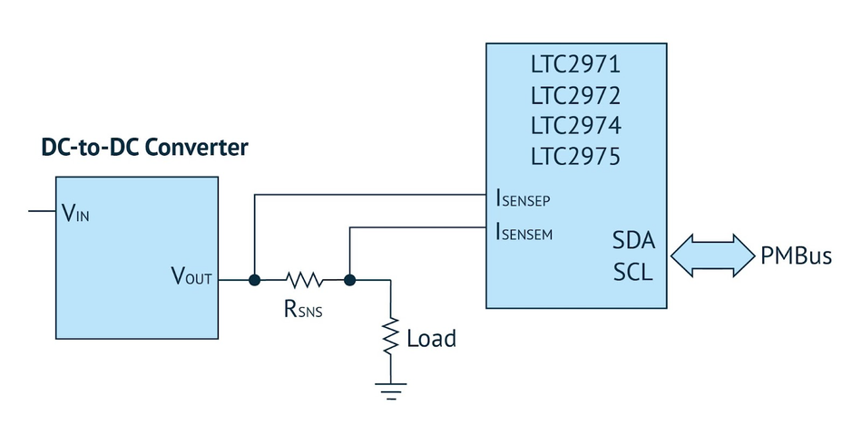
The LTC2971/LTC2972/LTC2974/LTC2975 (Fig. 1) managers accurately measure output current. Engineers select these devices for their dedicated current sense pins and PMBus commands that provide telemetry values in amps. Accuracy, cost, board space, and many other factors must also be considered before picking a current sensing solution.
Shunt Resistor Sensing
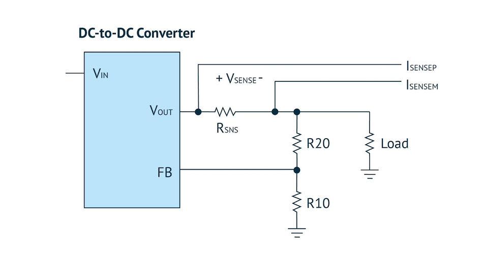
The most common sensing method uses a shunt resistor, sometimes called a current shunt. The shunt resistor is placed in series with the output, whether the DC-to-DC converter is a switching regulator or a linear regulator. The feedback resistor divider gets connected to the output node.
The shunt is inside the feedback loop, which allows the regulator to compensate for the shunt resistor’s IR drop (voltage drop across the shunt resistor) when the load current is applied. This significantly improves load regulation. Fig. 2 shows an application circuit for measuring the current through the load at the output of a DC-to-DC converter.
The data sheet specifications list the maximum differential sense voltage developed across the ISENSE pins. Most of the LTC297x devices can sense ±170mV of differential voltage. This provides more than enough range for most applications.
The max sense voltage gets calculated as follows: VSENSE = RSNS × IOUT(MAX). Generally, the max sense voltage is determined first, and the RSNS current sense resistor gets calculated as follows: RSNS = VSENSE / IOUT(MAX).
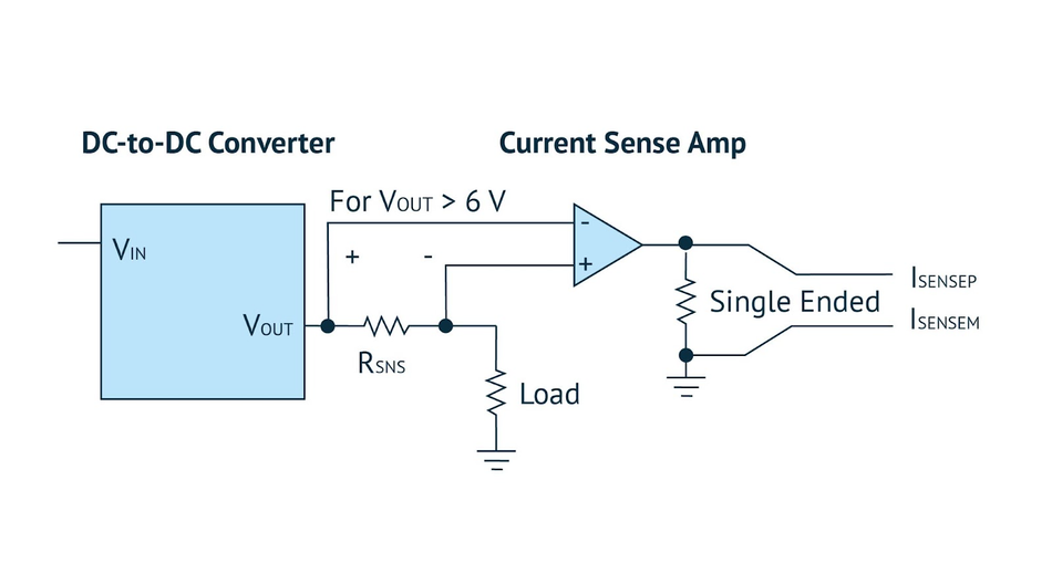
A related method adds a ground-referenced Current Sense Amplifier (CSA) to provide a single-ended output fed into the manager’s current sense pins. This approach gets typically employed for level translating a rail that is higher than the 6V limit of most LTC297x managers. The CSA should have good high-side common-mode performance. It is typical to power such a device from the sensed rail and GND as shown in fig. 3.
Inductor Direct Current Resistance (DCR) Sensing
DCR sensing is the method that senses current through a buck regulator’s output inductor. An inductor can get modeled as an ideal inductance in series with a resistance called DCR as shown in Fig. 4. This is typically the preferred method for high current (>20A) rails. The addition of a resistive shunt is an extra component that dissipates power and generates heat.
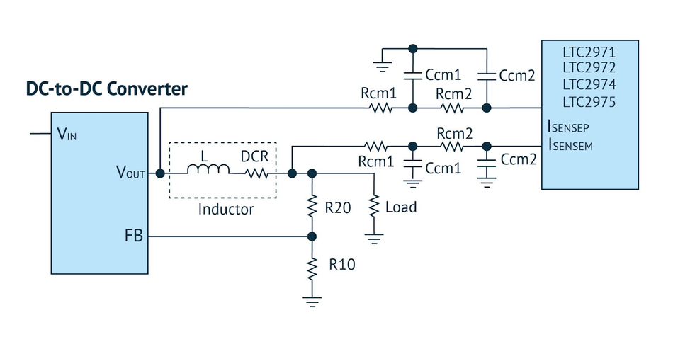
One must have access to both ends of the inductor to sense across it, and a filter network must be inserted between the sense points and the LTC297x sense pins. The filter network is a two-stage differential RC low-pass filter. A 4-element resistor array can also be employed for convenience and a small footprint.
An alternative filtering scheme uses only two resistors and two capacitors. This reduces the component count from eight to four; however, the filter performance does not remain as good Fig. 5 shows the modified application circuit of DCR inductor sensing with reduced components.
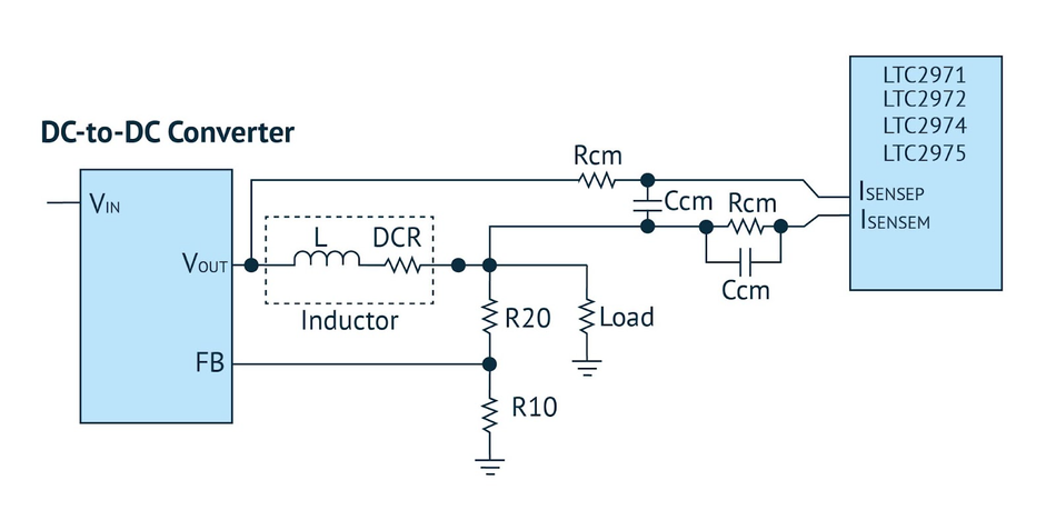
Table 1 shows a comparison between different current sensing options available for the DPSM family.
| Shunt Resistor | Inductor DCR | IMON |
Accuracy | Very good | Good | Good, however light load accuracy is generally not specified |
Output Path | Lossy (IR drop) | No additional losses | Lossless |
Filter | 1-pole filter per pin | 2-pole filter per pin | Single RC |
Other | – | – | Virtually no common-mode limitations, offset voltage on IMON pin on some devices |
Conclusion
This article introduced readers to DPSMs and some primary current sensing methods. It showcased how DPSM devices help designers simplify and accelerate power system characterization, optimization, and data mining during prototyping, deployment, and field operation.
This article is based on an e-book by Mouser and Analog Devices. It has been substantially edited by the Wevolver team and Electrical Engineer Ravi Y Rao. It's the third article from the Power Management for Tomorrow’s Innovations Series. Future articles will introduce readers to some more power management and optimization techniques for modern electronic systems.
The introductory article covered the fundamentals of power electronics, the technology behind highly-efficient power conversion in different electrical/electronic systems.
The first article shares some design techniques for efficient power management in EVs. It covers how manufacturers can build significantly better vehicular electric power systems with systematic planning and innovative power electronic solutions.
The second article introduced readers to silent switching and how it prevents EMI at the source, rather than adding shields and filters to the product later.
The third article describes current measurement techniques using LTC297x series components by Analog Devices. It presents some application circuits and compares different approaches for current sensing in power electronic converters.
The fourth article discussed the problems associated with phase noise and experimentally showcased how power supply designs can be optimized to deal with them.
The fifth article featured Single-Inductor Multiple-Output architecture that integrates different power supply functionalities to drastically reduce the overall size and costs for wearables.
The sixth article describes how vehicular asset-tracking devices are powered with small, efficient power solutions and protected from electrical stresses.
The seventh article explains how designers can implement and validate proven power supply circuits for enabling the reliable operation of healthcare devices.
The final article dealt with a specific IoT power management solution for small, and portable gadgets. It showcases a nano-Power boost converter that ‘operates on fumes’ to make the most out of all the available energy.
About the sponsor: Mouser Electronics
Mouser Electronics is a worldwide leading authorized distributor of semiconductors and electronic components for over 1,100 manufacturer brands. They specialize in the rapid introduction of new products and technologies for design engineers and buyers. Their extensive product offering includes semiconductors, interconnects, passives, and electromechanical components.

References
[1] Analog Devices Inc. Digital Power System Management, Mouser Electronics, [Online], Available from: https://www.mouser.com/new/analog-devices/adi-digital-power-system-management/
[2] Michael Peters, ‘Current Sensing with PMBus Digital Power System Managers—Part 1’, Analog Devices, [Online], Available from: