Protecting Autonomous Vehicle Control Circuits
Article #7 of our Circuit Protection Series: Designer engineers must incorporate circuit protection early enough in the process of vehicle electronics to avoid last-minute revisions that can delay compliance approvals and potentially compromise circuit performance.

08 Dec, 2021. 8 minutes read
This is the final article in a 7-part series examining circuit protection. The series examines the challenges of high-speed circuit protection, as well as the many products and solutions used to solve them. This series is sponsored by Mouser Electronics, an online distributor of electronic components. Through their sponsorship, Mouser Electronics shares its passion for technologies that enable a safe and connected world.
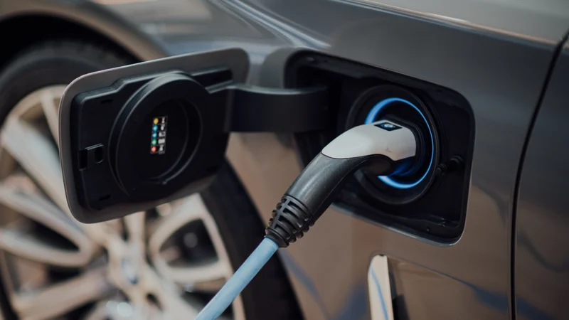
Those who follow autonomous vehicle technology are usually well aware of its benefits. But the safety and convenience autonomous vehicles offer can only come if the vehicle electronics are reliable and robust to electrical shocks such as lightning strikes (limited to the AC input of onboard chargers), in-vehicle power surges electrostatic discharge (ESD). Designer engineers must incorporate circuit protection early enough in the process to avoid last-minute revisions that can delay compliance approvals and potentially compromise circuit performance. The following is a look at what’s available.
Designers Have Choices
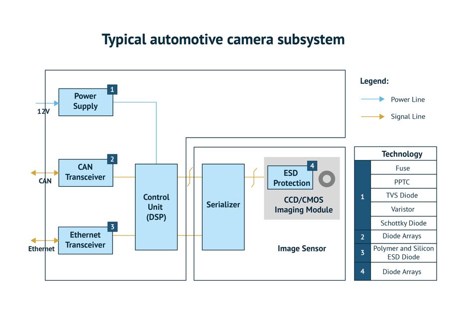
First, consider the case of the camera subsystem. Among other things, multiple cameras work together to provide depth perception and convert visual light through a charge coupled device/complementary metal oxide semiconductor (CCD/CMOS) image sensor into electronic signals sent to a communication and control circuit. Of the circuit blocks in a camera subsystem, those that require protection components connect with external circuitry (Figure 1). They typically include a Controller Area Network (CAN) transceiver, the power supply, and an Ethernet transceiver.
The camera power-supply subsystem requires protection from over-currents, high-energy transients, and ESD. A fuse provides over-current protection. Designer engineers can select either a conventional one-time blow, ceramic fuse, or a polymer-based, positive temperature coefficient (PPTC) resettable fuse. Both components can have wide temperature ratings for automotive requirements. Ceramic fuses can have operating temperature ratings of -55°C to +150°C, and PPTC resettable fuses can operate up to +125°C. The PPTC has the advantage of not needing replacement if it experiences an over-current. The PPTC substantially boosts resistance in response to the heat generated by an over-current. When the over-current is removed, the PPTC recovers to low resistance. Both component types come in surface-mount packages to save valuable printed circuit board (PCB) space.
Besides over-currents, power-supply circuits need protection from high-energy transients caused by in-vehicle sources such as motors turning on and off. The circuitry must be capable of withstanding transients defined by ISO Standards 7637 and 16750. Compliant components include transient voltage suppressor (TVS) diodes that can safely absorb both low-energy transients and high-energy transients as specified in Pulses 1, 2, 3, and 5 that the above-referenced standards spell out.
Design engineers can also consider a metal oxide varistor (MOV) for transient energy protection. MOVs can absorb transients with surge currents of 500A from 8×20-µsec pulses and up to 2.5J from 10×1,000-µsec pulses. These components comply with Electromagnetic Compliance Standard IEC 61000-4-2. MOVs can also safely withstand the automotive environment with an operating temperature range of -40°C to + 125°C.
To avoid catastrophic failure if the polarity of the voltage to the power supply accidentally reverses, designers can insert a Schottky diode in series with the fuse. Although providing reverse polarity protection, the diode’s low-forward voltage drop will have a minimal impact on power-supply performance.
The CAN protocol transceiver needs protection from ESD, fast electrical transients, and other overvoltage transients. Some diode arrays are specifically designed to protect the CAN lines without degrading. Diode arrays have high ESD tolerance, with models having 30kV air and 30kV contact discharge capabilities. These devices help designers meet the ISO 10605 standard for ESD in-road vehicles. Withstanding the high ESD voltages, the diode arrays can absorb up to 50A of transients defined by IEC Standard 61000-4-4 (Electrical Fast Transients). Furthermore, with a capacitance of about 15pF and leakage current under 1µA, the diode arrays do not interfere with protocol transmissions.
These devices also survive the automotive environment with a temperature operating range of -40°C to 150°C. Circuits designed to protect a CAN transceiver generally include a two-channel diode array on both the high and low lines. A single protection component containing both arrays is available and helps to reduce pick-and-place costs in production.
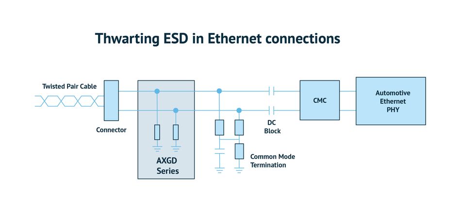
The Ethernet transceiver, such as the CAN transceiver, needs ESD and transient surge protection. Diode arrays and polymer ESD suppressors can provide the necessary protection for the high-speed differential data lines. Models of these diode arrays can provide up to ±30kV ESD protection and can absorb up to 50A of Electrical Fast Transients.
Diode arrays can protect a differential line pair in a single package to save space. Versions are also available as discrete components in 0402 and 0603 surface-mount packages to minimize capacitance and PCB space. These ESD protection devices cut signal distortion, reduce voltage overshoot, and simplify the circuit design. Capacitance values can get down to 0.35pF for the diode array and down to 0.04pF for the polymer ESD suppressor. These parameters ensure the ESD protection does not impede 1Gbit Ethernet transmission rates.
The image sensor is the most important circuit block. A single pair, bipolar set of ESD diodes can protect the image sensor and its circuit. The diodes in this bipolar protection component are oriented cathode to cathode. This model of TVS diode can withstand an ESD strike of up to ±30kV and has an extremely low leakage current with typical values of under 10nA. Its capacitance is around 0.35pF. These TVS diode arrays have ultra-small, 1.0mm × 0.5-mm SOD882 packaging to minimize board space. Keeping protection components as close as possible to the circuit inputs keeps extraneous energy from damaging critical parts.
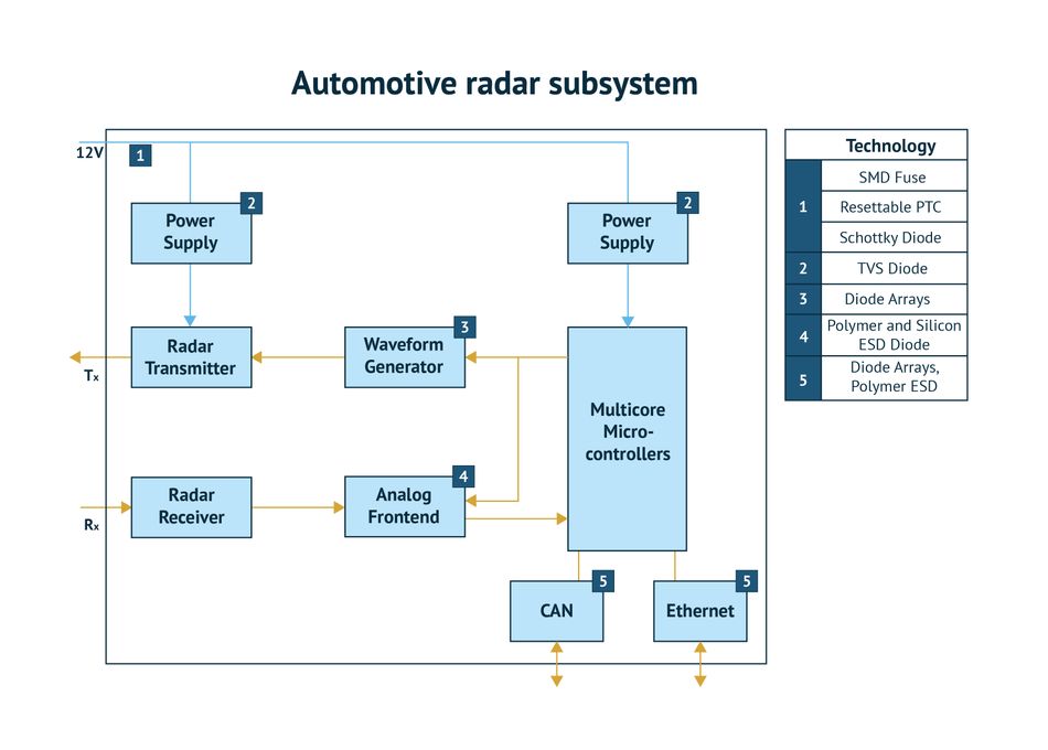
The radar subsystem provides the input for forward and side pedestrian detection and collision avoidance (Figure 3). The circuit generally has two DC power supplies, a low-noise supply powering the analog radar transmitter and receiver circuit blocks, a conventional supply for the logic and communication circuits. Like the camera subsystem power supply, radar subsystem power supplies need over-current protection, transient surge protection, reverse polarity, and ESD protection.
One set of protection components can handle over-currents and reverse polarity for both supplies. Again, designer engineers can employ either a conventional surface-mount fuse or a PPTC resettable fuse. In series with the input line to both supplies, a low-forward-voltage Schottky diode will protect against reverse polarity for both power supplies and the radar subsystem circuit blocks. Designer engineers should provide each supply with surge protection at the input.
TVS diodes are the recommended surge protection component. They can absorb large amounts of transient power, such as 600W for 1msec. These diodes can also absorb up to 100A of transient current. Designers select a TVS diode based on its transient power rating (400W/600W for low-power transients and 1,500W/7,000W for high-power transients).
The waveform generator and the analog front end are part of the radar transmitter and radar receiver. They are separate from the transmitter and receiver blocks because protection components on the transmitter output and receiver input blocks would alter their transmission and reception impedance. The protection components safeguard as much of the circuits as possible. A bipolar diode array is the recommended component for ESD protection.
A component similar to the diode array protecting the image sensor in the camera subsystem will provide the necessary ESD protection. The high-sensitivity analog front end requires ESD protection that will not interfere with the circuit’s low-level signal integrity. Designers should consider a bipolar polymer ESD suppressor. The ESD suppressor has a capacitance below 0.1pF and draws under 1nA of leakage current for a minimal impact on the circuit’s gain and bandwidth.
As with the camera subsystem, the radar subsystem sends its information to the vehicle central processing subsystem. Bipolar diode arrays provide ESD protection for both the high and low sides of CAN I/O lines. The Ethernet transceiver can use either diode arrays or polymer ESD suppressors to minimize signal distortion and not impact the Ethernet transmission rate.
The radar system is crucial for the safe, proper operation of an autonomous vehicle. It is, like the camera system, the set of eyes that monitor the road. Protection of its circuit blocks from the external environment is essential.
Protecting the ADAS
The signal processing, communication, and control subsystem operate the vehicle. This main subsystem must be robust, reliable, and fail-safe. The circuit must react to other vehicles in traffic and make fast stops when an animal or person obstructs the vehicle’s path. The subsystem also must have a fail-safe response to a failed sensor. All circuit blocks that supply information to the controller need protection from ESD.
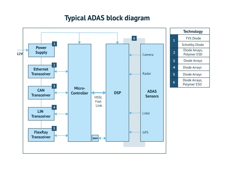
Like the other power-supply blocks, the ADAS power supply (Figure 4) requires over-current protection, surge protection, and reverse polarity protection. The fuse for this supply can reside within the module or further upstream in the vehicle’s low-voltage junction box. A TVS diode, picked for its surge power rating, protects against surge transients. A Schottky diode in series with the power supply input line provides reverse voltage polarity protection.
Each communication link requires ESD and transient protection designed for each port’s performance and configuration. Designer engineers can select from a wide range of diode arrays and polymer ESD suppressors to protect each communication link without compromising its data rate or its high-to-low voltage differential.
Any signal lines connecting directly to the DSP circuit block should have ESD and transient protection. Designers can use diode arrays or polymer ESD suppressors that provide bipolar protection for high and low signal lines.
The ADAS communication and control subsystem is the primary intelligence for autonomous vehicles. This subsystem must remain operational at all times. ESD protection on all ADAS inputs and outputs will protect the subsystem from disabling ESD strikes, and TVS diodes will protect against surge transients generated by electric and electromechanical devices.
Designers should be aware of the ISO standards with which vehicle electronic systems must comply. The most important of them include:
- Standard ISO7637-2: Defines requirements for protection from conducted electrical transients;
- Standard ISO16750-2: Describes environmental stresses that automotive electrical and electronic systems must withstand; and
- Standard ISO 10605:2008: Defines the ESD conditions that automotive electronics must withstand.
Familiarity with these standards helps design engineers avoid expensive and time-consuming re-designs.
The automotive industry has defined a qualification system for components that can be used in automotive electronic circuits. The components that pass a set of defined mechanical, electrical, and environmental stress tests, including operation over a wide temperature range, can be designated as AEC-Q (Automotive Electronics Council-Quality). Q values include AEC-Q100, AEC-Q101, and AEC-Q200. This qualification system determines which tests must take place. The use of AEC-Q-qualified components can enable a faster approval process for automotive electronic circuitry.
Conclusion
Robust, reliable vehicle electronic systems will help make autonomous vehicles fixtures on the road. Designers can substantially reduce the risk of circuit failures by providing over-current protection, transient surge protection, ESD protection, and reverse polarity protection.
This article was initially published by Mouser and Littlefuse in an e-magazine. It has been substantially edited by the Wevolver team and electrical engineer Fahad Farooq. It's the final article of a 7-part series examining circuit protection. Future articles provide an overview of how to protect wired communication, the change of USB standards, and the importance of protecting against electrical stress in industrial automation environments.
Article one gave an overview of general ports.
Article two introduces electrical stress.
Article three took a closer look at USB-C protection.
Article four highlighted issues with USB fast-charging.
Article five looked at RS-485 and Ethernet stress.
Article six gave an overview of circuit protection in factory automation.
About the sponsor: Mouser
Mouser Electronics is a worldwide leading authorized distributor of semiconductors and electronic components for over 1,100 manufacturer brands. They specialize in the rapid introduction of new products and technologies for design engineers and buyers. Their extensive product offering includes semiconductors, interconnects, passives, and electromechanical components.