Don't Lose Control of Your Factory Automation
Article #6 of our Circuit Protection Series: The Factories of the Future Will Demand Advanced Circuit Protection Technology to Keep Everything Connected.

24 Nov, 2021. 7 minutes read
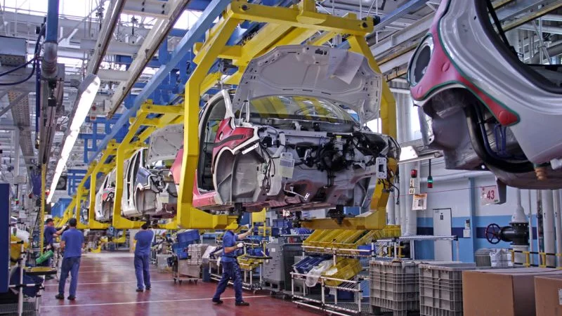
Image credit: Seylar
This is the 6th article in a 7-part series examining circuit protection. The series examines the challenges of high-speed circuit protection, as well as the many products and solutions used to solve them. This series is sponsored by Mouser Electronics, an online distributor of electronic components. Through their sponsorship, Mouser Electronics shares its passion for technologies that enable a safe and connected world.
The original Industrial Revolution marked the transition from making things by using human and animal power to making things with machines by harnessing water and steam power. The ability to use electricity in the mass production of goods made the second Industrial Revolution possible. The third came as the result of the use of computers to automate production processes.
The Fourth Industrial Revolution marks the transition from dumb machines (assembly lines, standalone automated painters, welders, etc.) to machines made smart and self-configurable sensors and processors. Further, these individual machines are connected to an operations center via the Industrial Internet of Things (IIoT), creating integrated networks. Also known as Industry 4.0, this shift aims to make production more efficient, cost-effective, and flexible and deliver a better product to the customer in less time.
The increased connectivity that the IIoT brings to factory automation systems makes these systems vulnerable to electrical damage from various threats. These threats include electrostatic discharge (ESD), electrical fast transients (EFT), cable discharge events (CDE), lightning-induced surges, and system-induced voltage transients that occur when large motors turn on or off, etc. This can happen via both data and power connections (Industrial Ethernet, Power over Ethernet (PoE), Controller Area Network (CAN) bus, RS-485, Profibus/FieldBus, etc.).
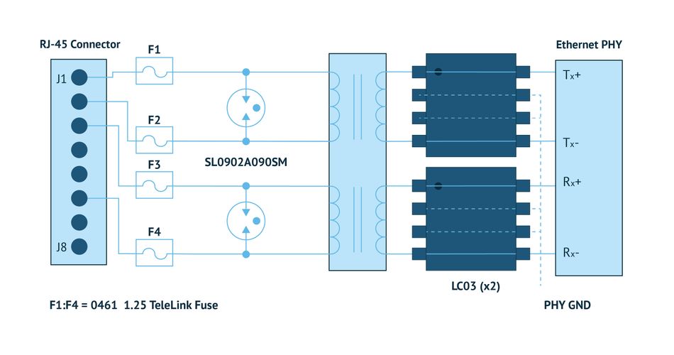
Some industrial Ethernet circuit protection applications pose greater challenges when applied in facilities with multiple buildings that has equipment and cabling located outdoors. Figure 2 shows a circuit protection scheme optimized for these applications involving severe outdoor exposure in environments with frequent electrical storms.
Engineers designing and implementing automation systems need to be aware of the appropriate circuit protection solutions, such as Transient Voltage Suppression (TVS) Diodes, TVS Diode Arrays, Gas Discharge Tubes (GDTs), and SIDACtor® protection thyristors, that can reduce or eliminate the risks involved. In the following article, we present an overview of circuit protection solutions that are particularly appropriate for various industrial automation applications and the advantages they provide for ensuring the reliability of the systems driving the factories of the future.
Industrial Ethernet
Industrial Ethernet (IE) combines standard Ethernet protocols with rugged connectors and high-temperature switches. Components used in industrial applications must be able to withstand temperature extremes, humidity, and vibration significantly beyond the ranges for equipment intended for installation in typical office environments.
Industrial Ethernet networks must interoperate with existing and legacy systems and provide predictable performance and maintainability. In addition to physical compatibility and low-level transport protocols, a practical industrial Ethernet system must also provide interoperability of higher levels of the Open Systems Interconnection (OSI) model. An industrial network must provide security both from intrusions from outside the plant and from inadvertent or unauthorized use.
Figure 1 illustrates one approach to indoor long-haul data line (not PoE) protection against lightning-induced transients, ESD, EFT, CDE, and power faults that’s appropriate for use in a factory automation environment.
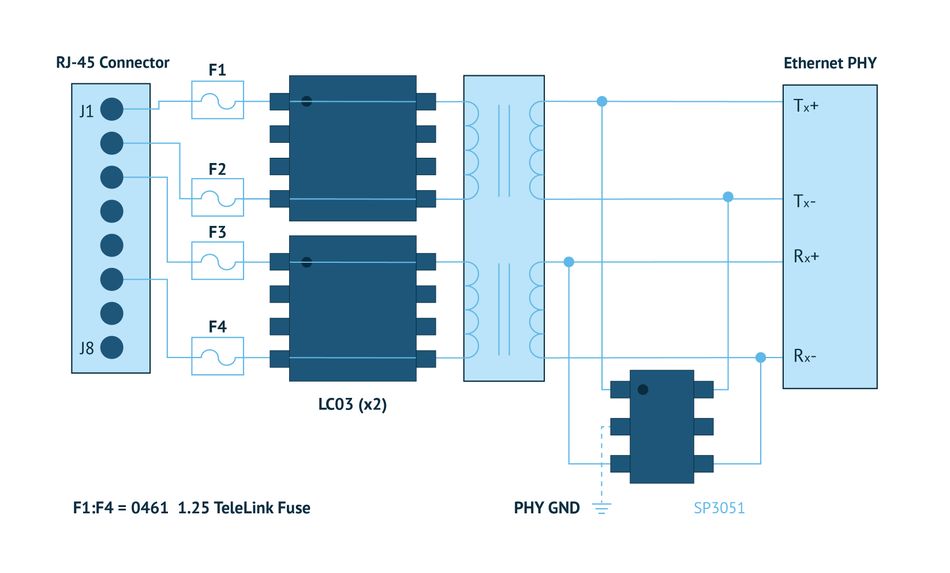
Figure 1: One approach to indoor long-haul Ethernet data line protection against lightning, ESD, EFT, CDE, and power faults. The four data lines shown (Tx± and Rx±) are protected against intra-building lightning transients. The LC03 TVS Diode Array diverts the majority of energy away from the transformer, but any common-mode energy that does get coupled across the transformer interwinding capacitance is diverted to GND by the SP3051 TVS Diode. This component can be connected to the ground on the PHY side of the transformer because the transformer itself meets the IEEE 802.3 isolation requirements. (Source: Littelfuse)
Some industrial Ethernet circuit protection applications pose greater challenges when applied in facilities with multiple buildings that has equipment and cabling located outdoors. Figure 2 shows a circuit protection scheme optimized for these applications involving severe outdoor exposure in environments with frequent electrical storms.
Power Over Ethernet
PoE describes several standardized or ad-hoc systems that pass electrical power and data on Ethernet cabling. This allows a single cable to provide both data connection and electrical power to various devices such as IP security cameras. Unlike the USB bus, which also powers devices over the data cables, PoE allows for extended cable lengths. Power can be carried on the same conductors as the data or on dedicated conductors in the same cable. In a PoE scheme, the device that receives the power is called the client device or Powered Device (PD), and the device supplying the power is the Power Sourcing Equipment (PSE). Mode A power is supplied over the active data pair found in 10BaseT or 100BaseTX interfaces. Mode B power is applied over the unused pair for 10BaseT and 100BaseT interfaces. For 1000BaseT and 10GbE applications, all wire pairs are used for data transfer, so no spare pairs are available. Figure 3 illustrates circuit protection schemes for PoE Powered Device and Power Supply Equipment.
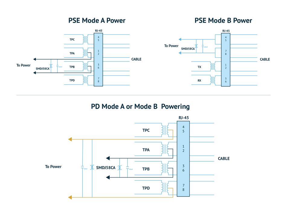
Figure 3: Here, a properly rated transformer and power supply provide the required isolation for IEEE 802.3 compliance. For the PSE, TVS Diodes are used on the specific pair(s) to provide the power. Shown here are 1500W versions for high-exposure cable and equipment installations. For short cables or installations where lightning exposure is not expected to be high, lower-power 600W or 400W components can be used. For the protection of the PD, both pairs need to be protected as it will not be known ahead of time which pair(s) will provide power. TVS Diodes should be selected based on the expected surge exposure level. (Source: Littelfuse)
CAN Bus (DeviceNet)
IE and PoE are far from the only communication buses relied upon for factory automation system coordination. The CAN Bus standard allows microcontrollers and devices to communicate with each other in applications without a host computer. Although not nearly as fast as Ethernet, CAN Bus is highly robust and capable of communicating data reliably over substantially longer distances than Ethernet. That makes it a good choice for applications that require communicating instructions or returning data from separate pieces of equipment located some distance from each other. Figure 4 shows a typical CAN Bus application example. The DeviceNet network is based on CAN bus technology.
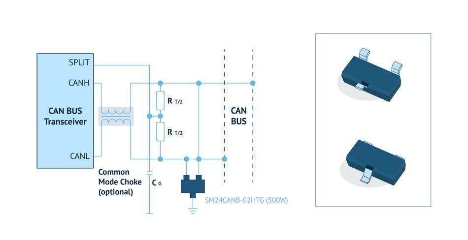
Figure 3: Here, a properly rated transformer and power supply provide the required isolation for IEEE 802.3 compliance. For the PSE, TVS Diodes are used on the specific pair(s) to provide the power. Shown here are 1500W versions for high-exposure cable and equipment installations. For short cables or installations where lightning exposure is not expected to be high, lower-power 600W or 400W components can be used. For the protection of the PD, both pairs need to be protected as it will not be known ahead of time which pair(s) will provide power. TVS Diodes should be selected based on the expected surge exposure level. (Source: Littelfuse)
RS-485 (Profibus, FieldBus)
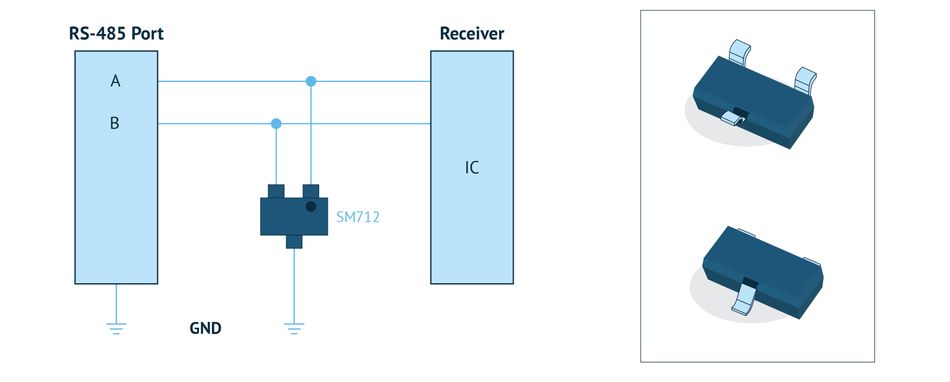
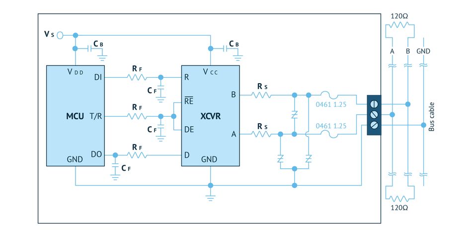
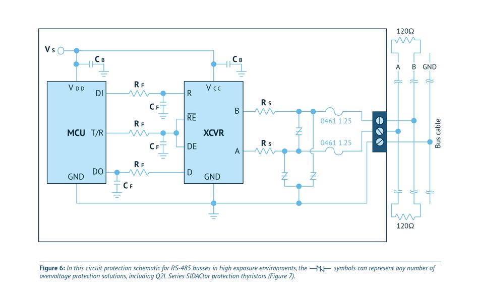
Much like CAN Bus, RS-485 is highly robust and offers industrial users the ability to transmit data without degradation over longer distances, but it’s somewhat faster than CAN Bus. In industrial settings, it’s often used for control of lighting, security cameras, and fire detection systems. Figure 5 illustrates one circuit protection solution for RS-485 ports subject to ESD or low-level transients because of lightning-induced surges. Figure 6 represents a higher level of protection.
Conclusion
Although system designers spend most of their time focused on the functionality of the communication system (that supports their factory automation project), it is essential not to overlook the electrical threats to which those systems will be exposed.
This article was initially published by Mouser and Littlefuse in an e-magazine. It has been substantially edited by the Wevolver team and electrical engineer Fahad Farooq. It's the 6th article of a 7-part series examining circuit protection. Future articles provide an overview of how to protect wired communication, the change of USB standards, and the importance of protecting against electrical stress in industrial automation environments.
Article one gave an overview of general ports.
Article two introduces electrical stress.
Article three took a closer look at USB-C protection.
Article four highlighted issues with USB fast-charging.
Article five looked at RS-485 and Ethernet stress.
About the sponsor: Mouser Electronics
Mouser Electronics is a worldwide leading authorized distributor of semiconductors and electronic components for over 1,100 manufacturer brands. They specialize in the rapid introduction of new products and technologies for design engineers and buyers. Their extensive product offering includes semiconductors, interconnects, passives, and electromechanical components.