Solving Fast Charging USB Type-C Cables Problems
Article #4 of our Circuit Protection Series. Better circuit design with temperature monitoring is needed to overcome common fast-charge issues.

11 Nov, 2021. 5 minutes read
This is the fourth article in a 7-part series examining circuit protection. The series examines the challenges of high-speed circuit protection, as well as the many products and solutions used to solve them. This series is sponsored by Mouser Electronics, an online distributor of electronic components. Through their sponsorship, Mouser Electronics shares its passion for technologies that enable a safe and connected world.
Cable-to-device connections can accumulate contaminants, causing them to heat up quickly, which can easily damage or destroy the cable and the mobile device. The fix: better circuit design with temperature monitoring. This article outlines common problems associated with USB Type-C fast charging and how to fix them.
Wireless charging for smartphones and other mobile devices is increasing, but charging cables are unlikely to disappear completely anytime soon. That’s because wired charging offers significant advantages over wireless charging for some users—primarily because wired charging offers far greater charging speed.
The USB Power Delivery (USB-PD) and USB Type-C Connectors and Cable Assemblies specifications developed by the USB Implementers Forum (USB-IF) are central to the latest generation of wired charging solutions. The USB Power Delivery Specification enables the maximum functionality of USB by providing more flexible power delivery and data over a single cable.
Fast chargers and cables compliant with USB-PD and USB Type-C specifications can support charging power levels up to 100W. Depending on the device involved, that means that they can recharge a phone or other device much faster than a wireless charger. A wired charger with a long enough cable also allows users to keep interacting with their devices while they’re recharging, a significant advantage for the phone-addicted among us.
As crucial as these advantages are to users, it’s equally essential for designers to consider the safety issues associated with power and temperature management at the cable-to-device connection. Without proper circuit design, including temperature monitoring, cables and connectors can accumulate contaminants inside the connection, causing them to heat up quickly, easily damaging or destroying the cable and the mobile device.
Basics of USB Type-C Wired Charging
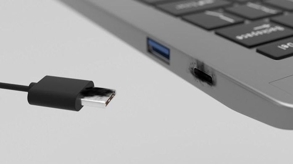
Three individual items must work together in any charging system—the device being charged, the cable, and the charger. USB Type-C (or USB-C) cables have one or more symmetrical (and, therefore, reversible) 24-pin connectors. USB-C chargers have an AC plug on one end (for plugging into a wall outlet) and either a cable with a USB-C connector on the other (for plugging into the device to be charged) or a USB-C output port for plugging in a USB-C cable.
From a safety standpoint, USB-C cables must be capable of carrying appropriate voltages and currents. For chargers with captive or fixed cables, the cables must handle the charger’s maximum voltage output. Cables with USB-C plugs on each end must be capable of driving 21V and at least 3A. Cables that incorporate special e-marker integrated circuits can carry 5A of current. Any device placed in the path of power, especially protection devices, must also manage these levels of voltage and current.
Sources of USB-C Charging Damage
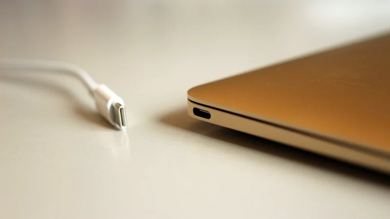
USB-C connectors’ pin pitch is 0.5mm—much tighter than the 2.5mm pin pitch in USB Type-A connectors. This tighter pitch significantly increases the risk of a fault that could cause a thermal event. When connector pins become deformed or dust, metal particles, hair, or other debris gets stuck in a USB-C cable connector, a resistive fault can be created from the power line to the ground. These resistive faults can cause a dangerous temperature rise while increasing current only minimally. Damage to both cables and devices, even fire, has been reported (Figure 1).
The traditional approach to protecting USB cables from overheating involves locating either a polymeric positive temperature coefficient (PPTC) device or a mini-breaker (also known as a thermal cutoff) on the VBUS power line. The chosen device would be placed on a printed circuit board inside the connector to sense the resistive fault’s temperature rise.
However, using this approach when attempting to protect against up to 100W can challenge design engineers. One of the drawbacks of adding a protection device in the path of power is that its resistance, even if it’s just milliohms of resistance, can contribute to significant power loss, making it more difficult for manufacturers to meet mandatory efficiency requirements.
The close confines of a USB-C connector can also make it challenging to fit a protection device inside. Polymeric positive temperature coefficient (PPTC) devices suitable for protecting 60W chargers typically have a 1210 (3.2mm × 2.5mm) footprint, and mini-breakers are often even bigger. PPTCs and mini-breakers meant to protect 100W would need to be even more significant. Also, mini-breakers have relatively weak mechanical structures. The cable assembly process can deform the bi-metal materials from which they’re constructed, which would prevent them from protecting a heating fault.
PolySwitch setP Digital Temperature Indicators
One way to address these disadvantages is to place a different type of protection device in the communication channel (CC) of the USB-C connector rather than on the VBUS line. One of the latest devices developed to protect USB-C cables against over-temperature conditions is the compact (2.0mm × 1.2mm) PolySwitch setP digital temperature indicator (Figure 2). The setP device senses a temperature increase and then alerts the system to shut down the power flow.
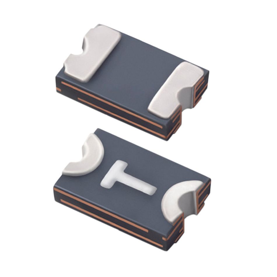
Here’s how it works: A setP digital temperature indicator is placed on the connector’s CC line, and when it senses temperatures higher than 100°C, it switches from a low-resistance state to a high-resistance state. This heightened resistance causes the voltage on the CC line to increase beyond the value defined by the USB Implementers Forum (USB-IF) to determine whether the source and sink are detached.
The charging system assumes that the cable has become detached because the voltage is higher than the value outlined in the specification, so the charging system turns off the power through the VBUS line. This prevents the connector, cable, and device from being charged from overheating. Once the user disconnects the cable and removes the connector’s debris, the cable can resume normal operation.
With a compact 0805 (2.0mm × 1.2mm) footprint, setP devices are at least 30 percent smaller than most other solutions used for this application in the past. Their rigid physical structure also allows them to withstand modern cable assembly and molding operations reliably. They’re well-suited for use in USB-C charging cables, USB Power Delivery charging cables, and chargers with captive USB Type-C cables.
Conclusion
USB-C cables offer owners a fast, uncomplicated way to recharge mobile devices and transfer data. With the development of a new solution for temperature indication, they can be confident that the process will remain safer.
This article was initially published by Mouser and Littlefuse in an e-magazine. It has been substantially edited by the Wevolver team and electrical engineer Fahad Farooq. It's the fourth article of a 7-part series examining circuit protection. Future articles provide an overview of how to protect wired communication, the change of USB standards, and the importance of protecting against electrical stress in industrial automation environments.
Article one gave an overview of general ports.
Article two introduces electrical stress.
Article three took a closer look at USB-C protection.
About the sponsor: Mouser Electronics
Mouser Electronics is a worldwide leading authorized distributor of semiconductors and electronic components for over 1,100 manufacturer brands. They specialize in the rapid introduction of new products and technologies for design engineers and buyers. Their extensive product offering includes semiconductors, interconnects, passives, and electromechanical components.