How to Charge a Lithium-Ion Battery Safely and Efficiently?
This article explains how to charge a Lithium-Ion battery safely and efficiently by covering charge profiles, voltage thresholds, current ratings, temperature derating, fast-charging limits, storage practices, and common design mistakes.

04 Jun, 2026. 13 minutes read
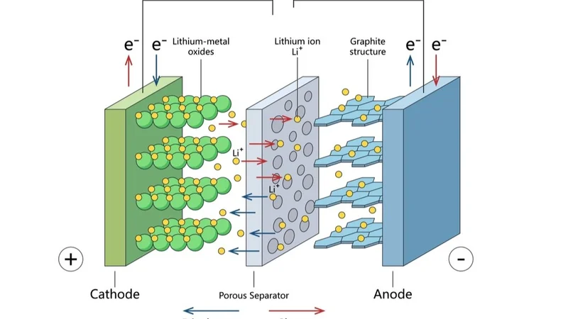
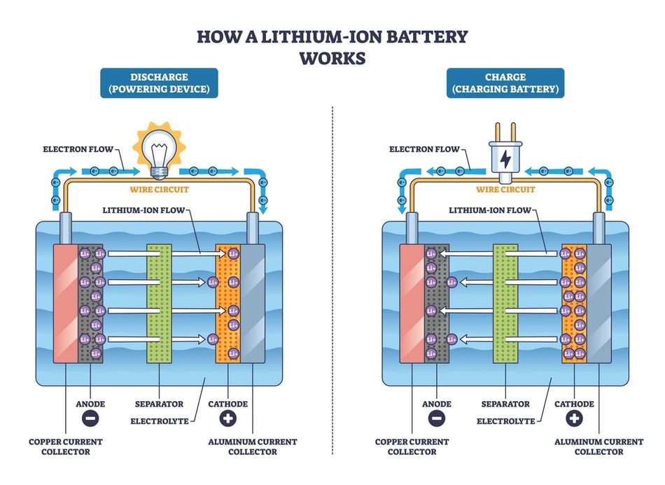
Lithium Ion Battery - Schematic
Key Takeaways
CC-CV Charge Profile: Modern Li-ion cells are charged with an initial constant-current (CC) stage followed by a constant-voltage (CV) stage. The transition occurs when the cell voltage reaches the set charge voltage. Full charge is reached when the taper current falls below ~3–5% of rated capacity.
Voltage and Current Limits: Typical NMC cells are charged to 4.2 V with a maximum current of about 1.6 A. The other cells use 4.2 V with a standard charge current of 2.45 A and a cut-off current of 0.02 C. LFP cells are charged to 3.6 V with a standard current of 3 A and can accept up to 26 A for fast charging.
Thermal Operating Windows: Most Li-ion chemistries must be charged between 0 °C and 45 °C. 50E by Samsung lists 0–45 °C for charging, MJ1 by LG specifies the same range, and prismatic LF280K by EVE permits 0–55 °C. Charging below 0 °C risks lithium plating; above 45 °C accelerates capacity fade.
BMS and Charger Integration: Pack managers provide cell balancing, over-voltage and over-current protection, temperature monitoring, and charge algorithms. Charger ICs support 4-A fast charging with programmable input current limiting and thermal regulation.
Float and Trickle Limitations: Unlike lead-acid batteries, lithium-ion cells do not benefit from a trickle or float charge at full state of charge. Li-ion chargers are voltage-limiting devices without a float stage, and keeping a cell at full voltage stresses the chemistry. The topping charge is applied only briefly when the voltage drops.
Introduction
Lithium-ion batteries power modern smartphones, laptops, electric vehicles, medical devices, and energy storage systems. However, charging these high-energy cells requires controlled electrical, thermal, and safety management. Then, how to charge a Lithium-Ion battery? It is not simply about connecting a power source; it involves following the correct current, voltage, temperature, and termination limits specified by the cell manufacturer. Improper charging can reduce cycle life, increase internal resistance, accelerate capacity fade, and create serious hazards such as overheating, swelling, or thermal runaway.
Engineers must understand how to charge a Lithium-Ion battery using the constant-current/constant-voltage method, supported by protection circuits and battery management systems. This article explains how to charge a Lithium-Ion battery safely and efficiently by covering charge profiles, voltage thresholds, current ratings, temperature derating, fast-charging limits, storage practices, and common design mistakes.
Li-ion vs LiFePO4 vs Lead-Acid Charging Differences
Lithium-Ion (Li-Ion) Batteries include several battery chemistries that use lithium-intercalation electrodes, but their charging requirements are not identical. Most portable electronics, including laptops and mobile devices, use nickel-rich chemistries such as lithium nickel manganese cobalt oxide (NMC) or lithium cobalt oxide (LCO). These cells typically have a nominal cell voltage of about 3.6–3.7 V, and charge to 4.20 V per cell.
Lithium Iron Phosphate, commonly referred to as LiFePO4, uses a lower voltage profile than nickel-rich lithium-ion chemistries. A typical LiFePO4 cell has a nominal voltage of about 3.2 V and charges to around 3.60–3.65 V per cell. This lower charge voltage changes the charger design, as the constant-voltage setpoint must be reduced relative to NMC or LCO cells. LiFePO4 batteries are widely used in energy storage, EVs, backup systems, and high-current battery packs because they offer strong thermal stability and long cycle life.
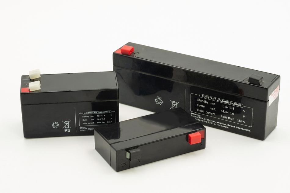
Lead-Acid Batteries use a different chemistry and charging strategy. They require staged charging: a bulk constant-current stage up to about 2.4 V per cell, a topping stage, and a float charge to maintain full capacity. Unlike lithium-ion, lead-acid cells tolerate trickle charging. The float charge helps offset self-discharge and sulfation. In contrast, lithium-ion packs should not be held at full voltage for extended periods, as elevated voltage accelerates electrolyte oxidation and capacity fade. When designing a charger that supports both lithium-ion and lead-acid, engineers must implement separate charging profiles.
Recommended Reading: NiMH vs Lithium Ion Batteries: A Comprehensive Comparison for Engineers
The CC-CV Charging Profile in Detail
The constant-current-to-constant-voltage profile is central to Li-ion battery charging.
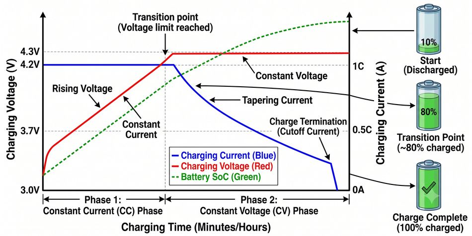
Constant Current Phase: Charging begins with a fixed current, typically between 0.5 C and 1 C for energy-type cells. The cell voltage rises gradually as lithium ions intercalate into the anode. For the Panasonic NCR18650B, the standard charge current is 1.625 A (0.5 C) [1]; for the Samsung 50E, it is 2.45 A [2]; for the LG MJ1, it is 1.675 A [3]. High-power cells can accept standard 3 A or fast 26 A charge currents. During this stage, the charger regulates current while monitoring cell voltage. If the battery is deeply discharged (below 2.5 V for many cells), a pre-charge at a lower current (typically 0.1 C) prevents lithium plating and reduces stress.
Constant Voltage Phase: When the cell voltage reaches the charge voltage (4.2 V for NMC cells and 3.65 V for LFP), the charger switches to constant-voltage regulation. The current naturally tapers as the electrochemical potential difference decreases. Full charge is reached when the current drops to 3–5% of rated capacity. For example, Samsung specifies a 98 mA (0.02 C) cut-off for the 50E, and MJ1 uses a 50 mA cut-off [3]. The battery is considered fully charged at this point.
Termination and No-Trickle Charge: Unlike lead-acid cells, lithium-ion cells should not be floated at a constant voltage once the taper-current threshold is reached. Battery University notes that Li-ion chargers are voltage-limiting devices and that manufacturers are very strict about the correct cut-off voltage because lithium-ion cannot tolerate overcharge. Some systems apply a brief topping charge when voltage drops, but continuous float charging is avoided. After termination, the charger disconnects or switches to a very low standby current.
Transition Detection and Control: High-precision voltage and current measurements are critical. Charger ICs integrate a switch-mode buck regulator with programmable current and voltage limits, ±0.5% voltage accuracy, and ±5% current accuracy [5]. They monitor the battery voltage via remote-sensing lines and adjust the duty cycle to maintain regulation. The transition from CC to CV is typically software-defined: when the cell voltage reaches the setpoint, the device enters a voltage-regulation loop and monitors the taper current to determine when to terminate.
Charge Voltage and Current Limits per Chemistry
Selecting the appropriate charge voltage and current is essential for safety and performance.
The table below summarises nominal voltage, charge voltage, standard charge current , and maximum charge current for several representative cells.
Cell (Chemistry) | Nominal Voltage | Charge Voltage / Cut-Off | Standard Charge (C-Rate) | Maximum Charge (C-Rate) |
Panasonic NCR18650B (NMC) | 3.6 V | 4.2 V, cut-off 65 mA | 1.625 A (0.5 C) | 1.6 A (~0.5 C) |
Samsung INR21700-50E (NMC) | 3.6 V | 4.2 V, cut-off 98 mA | 2.45 A (0.5 C) | 4.9 A (1 C) |
LG INR18650 MJ1 (NMC) | 3.635 V | 4.2 V ± 0.05 V, cut-off 50 mA | 1.675 A (0.5 C) | 3.35 A (1 C) |
A123 ANR26650m1B (LFP) | 3.3 V | 3.6 V, cut-off <50 mA | 3 A (~1.2 C) | 26 A (10 C) |
EVE LF280K prismatic (LFP) | 3.2 V | 3.65 V, cut-off 0.05 C | 140 A (0.5 C) | 280 A (1 C) |
Voltage Limits: NMC and other cobalt-blended chemistries charge to 4.2 V per cell. Some high-capacity variations may use 4.30 V, but higher voltage stresses the battery. Lowering the charge voltage prolongs cycle life: charging to 4.1 V instead of 4.2 V can increase cycle life by up to 50% at the cost of 10% capacity [4]. LFP cells operate at 3.65 V; pushing them higher risks overcharging because the LiFePO4 chemistry has a flat voltage plateau.
Current Limits and Fast Charge: Standard charge currents are typically 0.5 C for energy cells and up to 1 C for power cells. Fast charging at 1 C or higher reduces charging time but increases internal temperature. Some cells, such as the A123 ANR26650m1B, support up to 10 C continuous charge. However, most consumer cells limit fast charge to 1 C. Samsung allows a 4.9 A charge for the 50E (1 C) but notes that it should not be used for cycle life testing [2]. LG - MJ1 supports a maximum charge current of 3.35 A (1 C) [3]. When designing a charger, provide a user-selectable current limit and consider thermal derating.
Recommended Reading: Critical Design Considerations in Estimating the State of Lithium-ion Batteries
Temperature Constraints and Derating
Temperature strongly affects lithium-ion charging. Charging below 0 °C leads to lithium plating because the diffusion rate of lithium ions in the graphite anode slows, causing metallic lithium to deposit on the anode surface. The plated lithium increases resistance and can form dendrites that penetrate the separator, causing internal short circuits. Charging above 45 °C accelerates side reactions, gas generation, and SEI breakdown, reducing cycle life and raising the risk of thermal runaway.
Datasheets specify permissible charge temperature ranges. Samsung-INR21700-50E allows charging from 0 °C to 45 °C [2]. LG-MJ1 lists the same 0–45 °C charging range [3]. Panasonic-NCR18650 B does not explicitly list a temperature range in the publicly available spec, but similar NMC cells typically operate at 0–45 °C. The high-capacity EVE LF280K prismatic cell broadens the range to 0 °C–55 °C [6], reflecting the improved thermal stability of LiFePO4. In all cases, the discharge range extends to −20 °C or below, but charging at low temperature is prohibited.
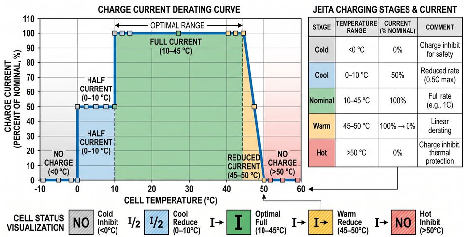
Derating Curves: Many BMS implementations reduce charge current as temperature approaches the extremes. JEITA (Japan Electronics and Information Technology Industries Association) guidelines specify a staged reduction: full current from 10 °C to 45 °C, half current from 0 °C to 10 °C, and no charging below 0 °C. Similarly, current is reduced above 45 °C and halted above 50 °C. Derating protects the cell from plating and thermal stress. Advanced charger ICs like the bq25898 implement thermal regulation and temperature-based derating with ±0.5% voltage accuracy and integrate battery temperature sensors. [5] Designers should tailor derating curves to the cell chemistry and intended environment.
Cooling and Heating: Large packs, such as EV battery modules, incorporate active thermal management. When ambient temperature is low, heaters warm the cells to above freezing before charging. In high-temperature environments, liquid or air cooling maintains cell temperature below 45 °C. Temperature sensors distributed throughout the pack feed data to the BMS, which adjusts charge current accordingly. Without thermal control, high-C fast charging is unsafe.
The Role of the Battery Management System (BMS)
Charging modern battery packs requires more than a simple voltage regulator. The battery management system monitors cell voltages, currents and temperatures, manages charge/discharge states, balances cells and protects against faults.
Cell Balancing: In series-connected battery packs, slight capacity variations cause individual cells to drift. If not corrected, some cells may reach the full-charge voltage earlier and become overcharged while others undercharge. The BQ40Z80 pack manager integrates cell balancing that bypasses current around higher-voltage cells during charging or at rest. Passive balancing dissipates energy as heat through shunt resistors; active balancing transfers charge between cells. The active schemes are more efficient but more complex. The pack manager can balance up to six series cells and natively supports batteries up to 29 Ah.
Protection and Fault Handling: A BMS implements over-voltage protection (OVP), under-voltage protection (UVP), over-current protection (OCP), short-circuit protection, and thermal cut-off. The BQ40Z80 includes programmable protection thresholds for voltage, current, and temperature, as well as a charge timeout monitor. It can shut off the charge and discharge FETs when a fault is detected. The BMS also stores error logs and lifetime data and supports cryptographic authentication to prevent counterfeit packs.
Charge Control and Power Path: Charger ICs act as the interface between the external power source and the battery. The bq25898 uses a high-efficiency buck converter to deliver up to 4 A charge current and supports input voltages from 3.9 V to 14 V [5]. It includes a Narrow VDC (NVDC) power-path architecture that allows the system to operate directly from the input source while charging the battery, ensuring a device can power up instantly even if the battery is deeply discharged. The chip senses input current and uses an input current optimizer (ICO) to maximize power without overloading the adapter [5]. It also features ±0.5% voltage regulation, ±5% current regulation, and thermal regulation with battery temperature sensing.
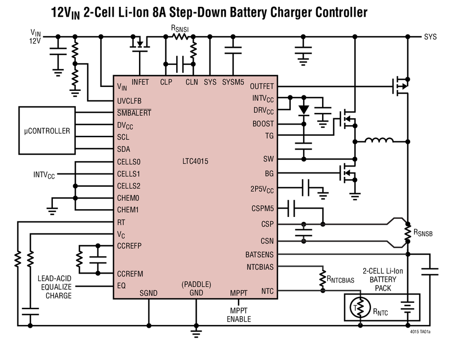
Telemetry and High-End Controllers: In higher-power applications such as energy storage systems, designers use multi-chemistry controllers like the Analog Devices LTC4015. This device can charge Li-ion, LiFePO4 or lead-acid batteries using a synchronous buck topology. It offers a wide input range of 4.5 V–35 V and supports battery voltages up to 35 V. An integrated 14-bit ADC measures battery voltage, current, battery resistance, temperature, input voltage, and system voltage. The device also includes coulomb counting and maximum power point tracking and can be configured via I²C. Such telemetry allows the BMS to estimate state of charge, health, and to implement adaptive charging profiles.
State Machine: A typical BMS state machine includes states such as idle, pre-charge, constant current charge, constant voltage charge, balancing, fault, and sleep. Transitions occur based on measured voltage, current, and temperature. Engineers should implement debounce timers and hysteresis to avoid oscillations between states. Safety features, including cutoffs for overvoltage, undervoltage, overcurrent, and high/low temperature, are enforced at each state.
Recommended Reading: Selecting Battery Management Systems Transformers for Isolated Communications in High-Voltage Energy Storage
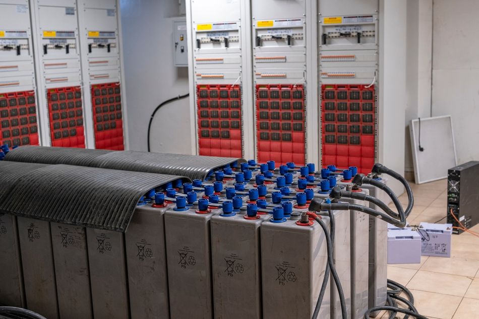
Applications of Lithium-Ion Battery Charging Systems
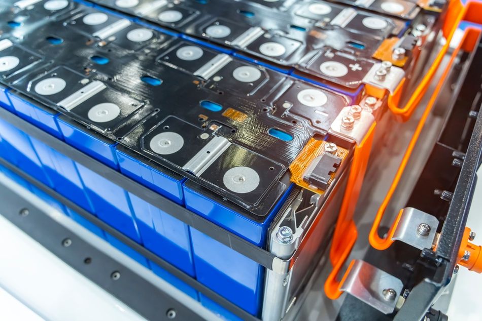
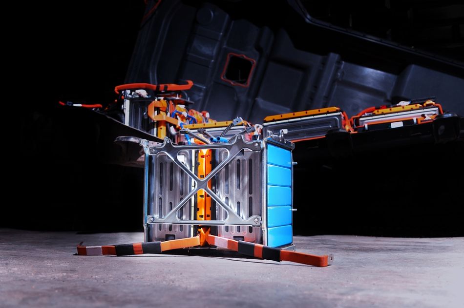 Electric Car Lithium Power Cell with Power Connections
Portable Electronics
Lithium-ion battery charging systems are widely used in portable electronics, including smartphones, laptops, tablets, wearables, cameras, and handheld instruments. In these devices, the charger must balance fast charging with heat control and long battery life. Most portable products use single-cell or multi-cell lithium-ion batteries with compact charger ICs and integrated battery management functions.
Electric Vehicles and Energy Storage Systems
In electric vehicles and high-voltage energy storage systems, charging becomes more complex. The charger must manage large battery packs, high charge current, thermal regulation, cell balancing, and communication with the BMS. EVs may use onboard AC chargers or external DC fast chargers, while grid-storage systems often prioritize lifespan, safety, and stable operation over maximum charging speed.
Medical, Robotic, and Industrial Power Systems
Medical devices, robotics, drones, and industrial power systems require reliable rechargeable battery operation under controlled voltage and temperature limits. In these applications, the charging process must protect against overcharging, deep discharge, and low-temperature operation. The correct charger design improves runtime, safety, cycle life, and system availability.
Fast Charging vs Slow Charging Trade-offs
Increasing charge current reduces charge time but accelerates degradation. High currents generate more heat and raise cell pressure. The constant-current phase shortens, but the constant-voltage phase still takes time because lithium diffusion becomes the rate-limiting step. Charging at 0.5–1 C fills a battery in 2–3 hours [4]. Fast charging at 1 C or higher can reduce the CC phase to about 1 hour, but the CV phase still requires tens of minutes. Frequent fast charging increases internal resistance and reduces cycle life. The compromise is to charge at a moderate 0.7–0.8 C and accept a 2-hour charge time. LFP cells tolerate higher C-rates, allowing EVs and energy storage systems to charge quickly; however, the BMS must monitor temperature and adjust current accordingly.
Storage Charging and Self-Discharge
Long-term storage at full charge stresses lithium-ion cells because the high voltage accelerates electrolyte oxidation. Storing Li-ion batteries at 40–60% state of charge extends calendar life. For large LFP prismatic cells like the EVE LF280K, the datasheet advises storing at 30–50% SoC and a temperature between 0 °C and 35 °C. Self-discharge is typically ≤3% per month, so periodic top-ups are unnecessary for a few months. For high-reliability systems, the BMS monitors voltage during storage and alarms if it falls below the UVP threshold.
The calendar aging is modeled as a function of time, temperature, and state of charge. Operating at 25 °C and 50% SoC can yield a calendar life of 10 years, while storing at 100% SoC and 45 °C may halve that. Engineers should design charging routines that bring cells to a mid-state of charge before long idle periods and implement storage-mode states in the BMS.
Recommended Reading: Enhancing Battery Health with Machine Learning
Common Mistakes and Safety
Many failures result from using the wrong charger or ignoring specifications. The key pitfalls include:
Overcharging: Applying a constant voltage higher than the rated value or using a charger that does not terminate at the correct taper current can plate lithium, causing thermal runaway. Standards like IEC 62133 require overcharge testing.
Deep Discharge: Allowing the cell voltage to drop below the UVP threshold (<2.0 V for many NMC cells) damages the electrodes. Chargers must pre-charge deeply discharged cells at a low current and BMSs must cut off discharge before reaching the damaging voltage.
Mechanical Damage: Crushing or puncturing a lithium-ion cell can cause internal short circuits. UN 38.3 testing includes shock, vibration, and crush tests to ensure cells can withstand transportation.
Thermal Runaway: Charging or discharging at high temperature can trigger exothermic reactions. The BMS must include thermal sensors and shut off charging if the cell temperature exceeds safe limits.
Using the Wrong Charger: The charger designed for another chemistry (e.g., lead-acid or NiMH) can overcharge or undercharge Li-ion packs. Always use a charger specifically rated for the cell chemistry and size. The charger must support the correct CC-CV algorithm and must detect the number of cells in series. For multi-cell packs, the charger should communicate with the BMS (e.g., via SMBus) to coordinate current limits and monitor cell conditions.
Conclusion
Properly charging lithium-ion batteries requires adherence to strict voltage, current, and temperature limits, implementation of the CC-CV protocol, and oversight by a robust BMS. Different chemistries (NMC, LFP and lead-acid) demand different voltage thresholds and charging currents. High-energy cells charge to 4.2 V at ~0.5 C, while LiFePO4 cells charge to 3.65 V and can handle high currents. Temperature derating and storage considerations are critical to prevent plating and extend lifespan. BMS solutions integrate power-path management, cell balancing, telemetry and protection.
Looking forward, smart chargers with machine-learning algorithms will adapt charging profiles to the cell's state of health, usage patterns, and environmental conditions. The solid-state batteries promise higher energy density and improved safety, but their charging behavior will still require careful management. USB Power Delivery (PD) and high-power DC fast-charging standards will enable faster charging for portable electronics and light electric vehicles, but only if chargers and BMSs communicate to negotiate current limits and ensure compliance with standards such as IEC 62133, UL 1642, and UN 38.3. Engineers must remain vigilant as battery technology evolves, balancing performance, safety and longevity.
Frequently Asked Questions
Q. How long does it take to fully charge a lithium-ion battery?
A. The charging time depends on capacity, charge current, and the selected charging process. A typical rechargeable lithium-ion cell charges in 2–3 hours at 0.5–1C, although fast charging can reduce charging time at the expense of battery life.
Q. Can I overcharge a lithium-ion battery?
A. Yes, but it is unsafe. Overcharging raises cell voltage beyond the rated limit, causing lithium plating, heat generation, and possible thermal runaway. A BMS and charger protection circuit help ensure the battery is charged safely within limits.
Q. What voltage should I charge a lithium-ion battery to?
A. Most lithium-ion cells charge to 4.20 V per cell, while lithium-ion phosphate batteries usually charge to about 3.65 V. The correct charge level depends on chemistry, datasheet limits, and battery pack configuration.
Q. What is the difference between charging a Li-ion and a LiFePO4 battery?
A. Standard Li-ion cells usually charge to 4.20 V per cell, while LiFePO4 cells use a lower voltage, around 3.65 V. Lithium-ion phosphate batteries offer better thermal stability but require different charger settings.
Q. How do I store a lithium-ion battery long term?
A. Store lithium-ion batteries at a partial charge level, typically 40–60%, in a cool, dry place. Avoid full charging or deep discharging during storage, as both shorten battery life and reduce future charging cycles.
Q. What is trickle charging and does my li-ion need it?
A. Trickle charging applies a small current to maintain a full charge, common in lead-acid batteries. Lithium-ion batteries do not need it. Continuous float or trickle charging can stress cells and reduce lifespan in rechargeable power systems.
Q. What is the role of the BMS in charging lithium-ion batteries?
A. BMS monitors voltage, temperature, current in amp levels, and cell balance during battery charging. It protects the battery pack from overcharge, deep discharge, overheating, and unsafe operation in portable devices and power systems.
References
[1] TME. NCR18650B Li-Ion Cell Datasheet [Cited 2026 June 4]; Available at: Link
[2] ResearchGate. Specification of Samsung SDI INR 21700-50E [Cited 2026 June 4]; Available at: Link
[3] Tynergy Power. Leadscrew Types: Acme vs Ball Screw vs Roller Screw [Cited 2026 June 4]; Available at: Link
[4] Battery University. BU-409: Charging Lithium-Ion [Cited 2026 June 4]; Available at: Link
[5] Texas Instruments. bq25898, bq25898D I2C Controlled Single Cell 4-A Fast Charger with MaxCharge™ Technology for High Input Voltage and Adjustable Voltage USB On-the-Go Boost Mode [Cited 2026 June 4]; Available at: Link
[6] EVE Energy. LF280K Prismatic Cell Specification [Cited 2026 June 4]; Available at: Link
in this article
1. Key Takeaways2. Introduction3. Li-ion vs LiFePO4 vs Lead-Acid Charging Differences4. The CC-CV Charging Profile in Detail5. Charge Voltage and Current Limits per Chemistry6. Temperature Constraints and Derating7. The Role of the Battery Management System (BMS)8. Applications of Lithium-Ion Battery Charging Systems9. Fast Charging vs Slow Charging Trade-offs10. Storage Charging and Self-Discharge11. Common Mistakes and Safety12. Conclusion13. Frequently Asked Questions14. References