Selecting Battery Management Systems Transformers for Isolated Communications in High-Voltage Energy Storage
Article 3 of the Power Conversion Series. Battery Management Systems (BMS) monitor essential safety factors in high-energy battery packs.
01 Apr, 2021. 8 minutes read
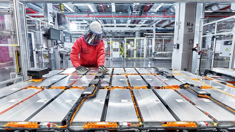
Image: Audi
This is the third article in a 5-part series exploring power conversion. The series will provide insight into how the rapid electrification of vehicles and the switch to renewable energy is driving the demand for safe and reliable power conversion and electronic components.
The articles were originally published in an e-magazine, and have been substantially edited by Wevolver to update them and make them available on the Wevolver platform. This series is sponsored by Mouser Electronics, an online distributor of electronic components. Through their sponsorship, Mouser Electronics supports engineers in designing sustainable and efficient applications for a greener future.
Introduction
Battery Management Systems (BMS) connect to high-energy battery packs and manage the charging and discharging of the pack. They also monitor essential safety factors, including temperature, state of charge, and the pack’s state of health. Providing additional application protection, the BMS can connect the battery and disconnect it from the load or charging source, as required.
This article provides an overview of the key features of battery monitoring Integrated Circuits (ICs) typically specified in BMS. It includes background information on battery-cell chemistries related to the requirements for communications in high-voltage BMS. An application example will explain the technology benefits that Bourns® transformers deliver to meet these specifications.
Overview of Lithium-Ion Battery Chemistries
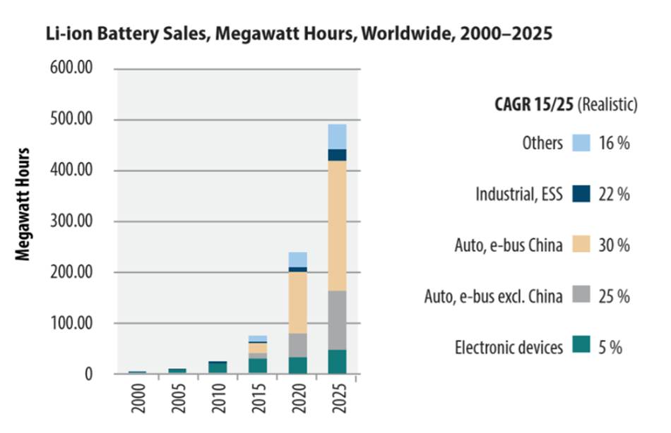
Consulting and market research firm Avicennes[1] has predicted that the usage of lithium-ion (Li-ion) battery cells for energy storage and automotive applications will continue to grow significantly through 2025 with compound annual growth rates up to 30 percent forecasted in China’s transport sector. As Li-ion usage grows and expands into new applications, it is important to understand the nature and use of various battery chemistries.
Table 1 summarizes the most popular chemistries by energy density, cell voltage, and charge rate for 48V and higher voltage battery packs. These next-generation packs match the power density required to drive new electronics and motor designs. The latest battery cell developments in different chemistries deliver the increased power energy over longer periods necessary for full-electric battery power.
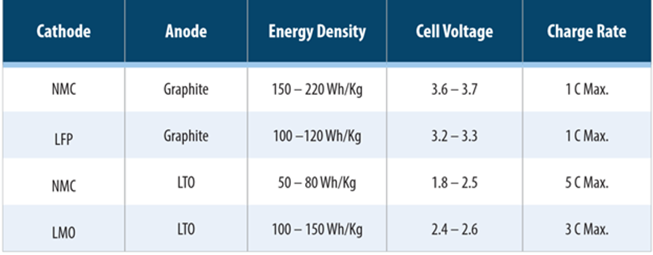
There are several factors to consider when choosing the chemistry for a battery-powered application. As can be seen in Table 1, Lithium Nickel Manganese Cobalt (NMC) with Graphite has the highest energy density among the commonly used chemistries. This is advantageous for heavy loads such as consumer energy storage or plug-in electric vehicles. However, the disadvantage of this chemistry is that it creates a higher risk of lithium plating on the anodes, which can reduce battery life and lead to thermal runaway (fire or explosion). The potential for these harmful conditions can be exacerbated by today’s faster-charging connectors.
Lithium Titanate (LTO) has a lower energy density than NMC and does not suffer from the problem of cracking graphite, which together improves the estimated battery life. The lower internal resistance of LTO facilitates faster-charging rates making this battery chemistry beneficial for plug-in electric vehicles (EVs). The downside is the higher cost for heavier battery packs as more cells are needed to provide the necessary energy in kilowatt hours (kWh).
Lithium chemistries have very narrow operating temperature ranges, typically from 20°C to 40°C. Operating outside these temperatures leads to a loss of capacity and a shorter lifespan. Elevated temperatures can also cause further degradation and a thermal runaway condition. A paper by NASA, which studied the protection within 18,650 cells, found that the interrupt devices in all the cells connected in series and parallel were not as effective as single cells in preventing thermal runaway during fault conditions[2]. This study illustrates the strong need for a Battery Management System when multiple cells are interconnected.
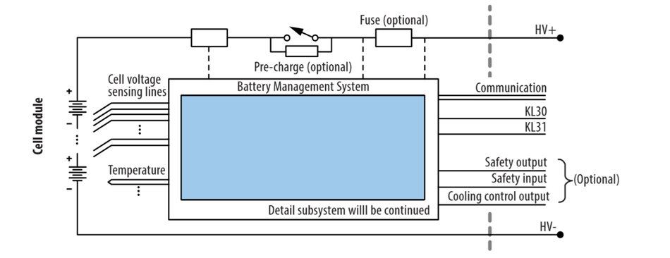
A typical battery monitor IC (Figure 3) measures cell voltage and pack temperature and performs cell balancing. In some models, there is also a current sense input port for shunt-based current measurement. Including this feature makes sense in 48V systems that use a limited number of battery cells and do not experience hazardous voltage levels and, hence, monitoring ICs.
Conversely, it does not add a lot of value to integrate a current sense function into an IC for high-voltage battery packs. These packs require only one current sensing chip and several monitoring ICs to monitor the pack’s individual cells. For instance, the 2011 Nissan® Leaf® has a working voltage of 360V and energy of 24kWh (NMC technology)[3]. The structure of the pack is 96S2P (192 cells). A simpler way to put it: If each monitoring IC can check 10 cells, then at least 20 monitoring ICs will be needed. Another consideration in high-voltage battery packs is that the BMS IC module or board must be located on top of the shunt resistor, which can pose a mechanical design challenge.

BMS High Voltage Communications
The BMS typically has two ports for isolated communications, allowing battery monitoring modules to be daisy-chained throughout the battery pack. The source and sink currents of the serial port drivers are balanced, enabling the IC to drive a transformer without saturating it. With a rated working voltage of several hundred volts, the transformer provides the necessary protection of the communications line from any hazardous voltage coming from the battery pack. Furthermore, the drivers on the IC encode a four-line serial peripheral protocol into the differential signal needed for isolated communication from board to board.
Serial Peripheral Interface (SPI) is an interface bus commonly used to send data where one device or “master” transmits a clock pulse and control bit to a series of slaves. On each clock pulse, the slave either reads a command from the master, or transmits its data on the data line if the control bit is inverse. In this way, a central battery controller IC (master) can interrogate each monitoring IC (slave) in turn and retrieve necessary voltage and temperature information from the whole pack. In addition, the transformer and integrated common mode choke filter out common-mode noise from the daisy-chained network.
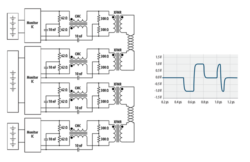
Although BMS ICs have balanced currents on their I/O pins, most manufacturers recommend a center-tapped transformer. These have been found to improve Common Mode Noise Rejection (CMNR) if a filter capacitor and termination resistor are used, Figure 4.
Bourns® BMS Transformer Safety Features
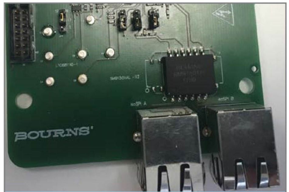
The windings inside the Bourns® Model SM91501AL transformer use enameled fully insulated wire (FIW) that passes the dielectric strength (Hi-POT) test of 4.3kV (1mA, 60 seconds). Per Table 2N of IEC 60950[4], the minimum creepage distance for material group I, pollution degree 2 of functional insulation for a working voltage of 1600V is 8mm. The Bourns® Model SM91501AL transformer datasheet shows a minimum 10mm creepage distance. This is because the actual tracking distance over the transformer’s surface and chokes has been calculated at 10.4mm in the samples measured.
The replacement test for IEC 60950 (IEC 62368-1)[5], which becomes mandatory in June 2019 for audio/video, information technology, and communication equipment will recognize FIW in the future. The use of FIW might qualify the device as having reinforced insulation with a lower working voltage (depending on the standard) of approximately 800V. This might allow the device to meet UL listing requirements and enable its use in additional applications such as consumer energy storage, which mandate reinforced insulation.
Recommended Electrical CharacteristicsSome IC manufacturers’ recommended primary inductance values will depend on the voltage of the communication signals, the pulse widths, and the frequency. Bourns designed its Model SM91501AL transformer with a primary inductance span between 150µH and 450µH over an operating temperature range of -40°C to +125°C. The inductance is directly proportional to the permeability of the core. The permeability of the ferrite core of a transformer is temperature-dependent and tends to increase with temperature. Therefore, the Bourns® model’s primary inductance will drift up toward 450µH at the upper end of the temperature range. This is the reason for the large variation in the inductance value, as specified on the datasheet.
The BMS IC and transformer’s noise immunity can be evaluated using a bulk current injection (BCI) test. The BCI test injects current into the twisted pair lines at set levels over a frequency range of 1MHz to 400MHz with the bit error rate being measured. A 40mA BCI test level is sufficient for most industrial applications. The 200mA test level is typically used for automotive testing. The Bourns® Model SM91501AL and SM91502AL have been evaluated by certain BMS IC manufacturers for select automotive applications and have successfully passed BCI requirements.
Summary and Conclusions
Li-ion battery power demand is predicted to grow at a CAGR of 20 percent to 30 percent over the next eight years. Battery Management Systems that integrate isolated communications are expected to be an important part of the battery system’s safety and security. An effective and reliable BMS will help increase Li-ion cells’ lifespan while also enhancing safe operation for end-users.
Offering an optimal protection solution for isolated communications in industrial and consumer BMS applications, Bourns engineered its latest Model SM91501AL and SM91502AL BMS transformers with the higher working voltages of 1600V and 1000V, respectively. They feature an inductance value of 150µH and 450µH over an operating temperature range of -40˚C to + 125˚C, which meets higher voltage BMS requirements. Additionally, the transformer windings use fully insulated wire passing the dielectric strength (Hi-POT) test, further increasing electrical insulation protection for overvoltage transients.
Bourns® Model SM91501AL and SM91502AL have been tested by several BMS IC companies in their test laboratories which found them to function well with their chipsets, passing the necessary BCI tests.
This article was originally written by Mouser and Bourns in an e-magazine and substantially edited by the Wevolver team. It's the third article of a 5-part series exploring power conversion. Future articles will dive into power conversion solutions for critical applications such as automotive and renewable energy.
Article 1 explored how designers can make design decisions when working with high-voltage energy storage systems.
Article 2 discussed the potential of rechargeable batteries.
Article 3 examined the method for selecting transformers for Battery Management Systems (BMS).
Article 4 explained the necessity of shunt resistors to deliver accurate Battery Management Systems.
Article 5 provided an overview of innovative transformer solutions for power conversion.
References
1. Avicennes, Christophe, Pillot, Rechargeable Battery Market 2017-2025 The Battery Show, Hannover, May 15, 2018
2. NASA, Jeevarajan, Judith A., Safety Limitations Associated with Commercial 18650 Lithium-ion Cells presented at Lithium Mobile Power and Battery Safety 2010, Boston, MA
3. Hayes, J. G., & Goodarzi, G. A. (2018). Electric powertrain: Energy systems, power electronics and drives for hybrid, electric and fuel cell vehicles. Hoboken, NJ: John Wiley & Sons.
4. International Electrotechnical Commission, Information technology equipment – Safety – Part 1: General requirements IEC 60950-1 Edition 2, 2005
5. International Electrotechnical Commission, Audio/Video, Information and Communication Technology Equipment- Part 1: Safety Requirements IEC 62368-1 Edition 2.0 2014-02
About the sponsor: Mouser
Mouser Electronics is a worldwide leading authorized distributor of semiconductors and electronic components for over 800 industry-leading manufacturers. They specialize in the rapid introduction of new products and technologies for design engineers and buyers. Their extensive product offering includes semiconductors, interconnects, passives, and electromechanical components.