Getting to Know the Arduino UNO R4 Wi-Fi
The new Arduino UNO R4 Wi-Fi board provides built-in Wi-Fi and Bluetooth communication as well as a 12×8 LED matrix display to give makers, hobbyists, and engineers an extremely versatile prototyping tool.

03 Oct, 2023. 8 minutes read
Introduction
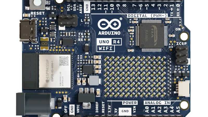
The Arduino® UNO R4 Wi-Fi is one of two boards in the Arduino UNO revision 4 series (the other being the UNO R4 Minima). The UNO R4 Wi-Fi incorporates an Espressif ESP32-S3 Wi-Fi® and Bluetooth® module and a 12×8 LED matrix on the PCB that supports the whole circuit. This LED matrix offers an exciting new way to deliver feedback and status, which typically require additional peripherals.
Like previous UNO revisions, the UNO R4 Wi-Fi works with UNO-compatible shields; but it also provides native Wi-Fi and Bluetooth connectivity and display features, making it very easy to start experimenting, exploring, making, and creating Wi-Fi, Bluetooth, and LED display projects right out of the box.
This article explores some of the exciting features of the Arduino UNO R4 Wi-Fi and demonstrates the setup and creation of a Wi-Fi and display project.
Project Materials & Resources
This project requires an Arduino UNO R4 Wi-Fi, a PC, a USB Type-C cable (compatible with the PC and the UNO R4 Wi-Fi USB Type-C port), and a Wi-Fi router. It is possible to use a smartphone hotspot as the Wi-Fi router to test and even run the code provided in this project.
Project Bill of Materials (BOM)
Project Code/Software
Project Technology Overview
The Arduino UNO R4 Wi-Fi maintains the same Arduino UNO form factor, pinout, and voltage operation (5VDC) to be backward-compatible with previous UNO version accessories. Compared to previous generations, the UNO R4 Wi-Fi provides expanded memory, a faster clock speed, and additional onboard peripherals (e.g., 12-bit digital-to-analog converter (DAC), CAN bus, op-amp). The board offers higher input voltage tolerance than prior generations (now up to 24VDC) as well as built-in support to emulate a mouse, keyboard, or other human interface device when connected to a PC. The UNO R4 Wi-Fi also includes an onboard Qwiic connector for easy I²C communication interfacing to sensors and actuators widely available for project boards. The board offers support for battery-powered real-time clock (RTC) operations plus an error-catching feature to provide enhanced diagnostics and runtime error detection.
That said, the main attractions of this new board are the built-in Wi-Fi/Bluetooth module and 12×8 LED matrix. The UNO R4 Wi-Fi can also use Arduino IoT Cloud services and can readily be set up as a cloud IoT sensor or actuator platform. Ultimately, the LED matrix eliminates the need for additional similar display accessories, providing you with data, animations, and other information directly on the board.
Table 1 presents the basic technical specifications of the Arduino UNO R4 Wi-Fi:
Board | Name | Arduino UNO R4 Wi-Fi |
SKU | ABX00087 | |
Microcontroller | Renesas RA4M1 (Arm® Cortex®-M4) | |
USB | USB-C | Programming Port |
Pins | Digital I/O pins | 14 |
Pins | Analog input pins | 6 |
DAC | 1 | |
PWM pins | 6 | |
Communication | UART | Yes, 1× |
I2C | Yes, 1× | |
SPI | Yes, 1× | |
CAN | Yes 1× | |
Power | Circuit operating voltage | 5V (ESP32-S3 is 3.3V) |
Input voltage (VIN) | 6–24V | |
DC current per I/O pin | 8mA | |
Clock speed | Main core | 48MHz |
ESP32-S3 | up to 240MHz | |
Memory | RA4M1 | 256kB flash, 32kB RAM |
ESP32-S3 | 384kB ROM, 512kB SRAM | |
Dimensions | Width | 68.85mm |
Length | 53.34mm | |
Table 1: Arduino UNO R4 Wi-Fi Technical Specifications. (Source: Arduino.cc)
Developing the Arduino UNO R4 Wi-Fi Indicator Project
This project begins with two main steps:
- Connecting the Arduino UNO R4 Wi-Fi to a PC and setting up the Arduino drivers and integrated development environment (IDE)
- Uploading the demo program (known as a sketch) of the demo code and modifying the code with the credentials of the target Wi-Fi network.
After these two steps the Arduino will run the sketch automatically and change state as the condition of connectivity with the Wi-Fi router changes.
Connecting the Board and Setting Up the IDE
Setting up the Arduino UNO R4 Wi-Fi with a PC is easy and relatively seamless. The following steps will guide you through the process, but you may need to make adjustments to get everything working smoothly on your configuration.
- Download and install the Arduino IDE from https://www.arduino.cc/en/software.
- In the IDE, install the Arduino UNO R4 Wi-Fi board packages.
- Click Tools, then click Board, then click Board Manager.
- Locate UNO R4 Wi-Fi, and install the latest version.
- You may need to restart your computer.
- Connect the USB Type-C cable to the UNO R4 Wi-Fi board, and connect the other end to your PC.
- Select the UNO R4 Wi-Fi from the board selector
- Click Tools, then click Board, then click Arduino UNO R4 Boards, and then select Arduino UNO R4 Wi-Fi.
- In the device selection menu near the check mark, right arrow, and play symbol, select your board. This will be Arduino UNO R4 Wi-Fi COM#, where “#” is the com channel assigned by your computer.
- Once connected, the yellow light labeled “L” on the board will blink, and the LED matrix will display a heart symbol. A prewritten Tetris animation also boots on reset, ending when the LED matrix displays a persistent heart symbol.
- In the IDE, click the check mark to compile the sketch.
- Once the code is compiled, click the right arrow to upload the sketch to the Arduino
Note: The author and designer experienced issues while attempting to upload the prototype sketch to the board. To successful upload the sketch, the author simply unplugging the UNO R4 Wi-Fi board USB connection from the PC, then plugged the USB connector back into the PC and immediately uploaded the sketch as soon as the board connected to the serial port.
Populating the SSID & Password in the Demo Sketch
To connect the UNO R4 Wi-Fi to a known Wi-Fi network, you must modify the SECRET_SSID and SECRET_PASS variables in the sketch, which represent Wi-Fi network SSID and password, respectively (Figure 1). The SSID is the name of the Wi-Fi network exactly as it is displayed when connected on a computer or smartphone. If necessary, consult your network administrator for the proper SSID and password to use to log into the network. Another option is to use a smartphone's hotspot.
For this demo, it is useful to have access to the Wi-Fi network, as you can experiment with the function of the code by turning on and off the Wi-Fi network.

To prevent the of accidental release of sensitive network information, consider putting SSID and password data in a separate header file (*.h) in the Arduino sketch. Then, as shown in lines 25 and 26 in Figure 1, change “SSID” to your Wi-Fi network name and “PASSWORD” to network's password. Then compile and upload the sketch.
After compiling and uploading the sketch, the demo code should work as described below.
Putting It All Together
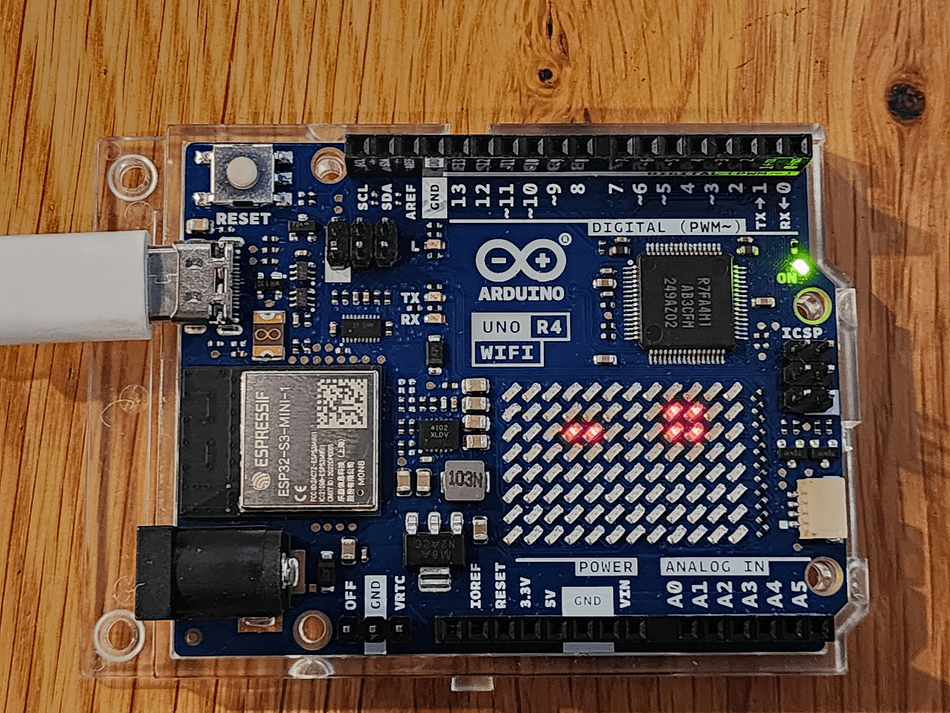
The Wi-Fi and LED matrix demo for the Arduino UNO R4 Wi-Fi is based on an example sketch provided by Arduino. Code from the Wi-Fi and LED matrix examples are combined and customized to create a fun Wi-Fi connection and status indicator with some personality. Upon boot, the sketch tells the LED matrix to display two "eyes" that wink for one second every nine seconds (Figure 2). This is a visual representation of the board's ten-second cycle, where it attempts to connect to a preprogrammed Wi-Fi network. Depending on your application's needs, you can further edit the sketch so the UNO R4 Wi-Fi connects to any open network or chooses between several different preprogrammed networks with passwords.
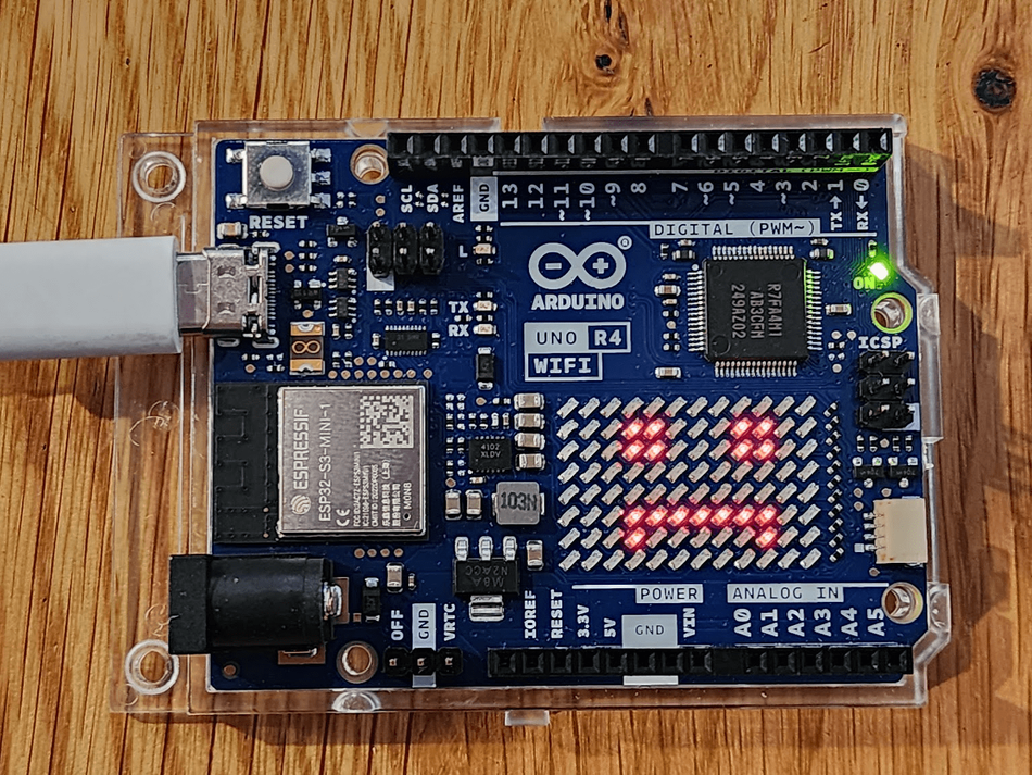
After an initial successful connection, the sketch continually checks the status of the connected Wi-Fi network and directs the LED matrix to display a smiling face that winks every second to show that the network is still connected (Figure 3).

If the connection to the Wi-Fi network is interrupted, the LED matrix displays a frowning face (Figure 4), and the UNO R4 Wi-Fi tries to reconnect every 10 seconds. Once reconnected, the display changes back to the smiley face that winks and displays a positive Wi-Fi status every second (Figure 3).
Conclusion
The Arduino UNO R4 Wi-Fi is an exciting new addition to the Arduino lineup, offering built-in Wi-Fi and Bluetooth connectivity and an onboard LED matrix display. These included features make the board extremely versatile for a wide range of IoT projects and products. Being compatible with Arduino UNO shields available for the R3 means that legacy projects can be given new life and retrofitted with incredible new capabilities without the need for additional Wi-Fi/Bluetooth and LED matrix display accessories.
This article was written by Jean-Jacques DeLisle for Mouser Electronics.