Active Filters: Types, Circuit Design, and How They Compare to Passive Filters
This article explores active filter types, circuit design principles, frequency response, and key differences between active and passive filters.

Last updated on 27 Jul, 2026. 17 minutes read
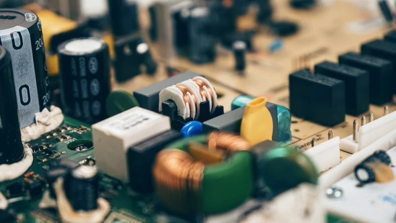
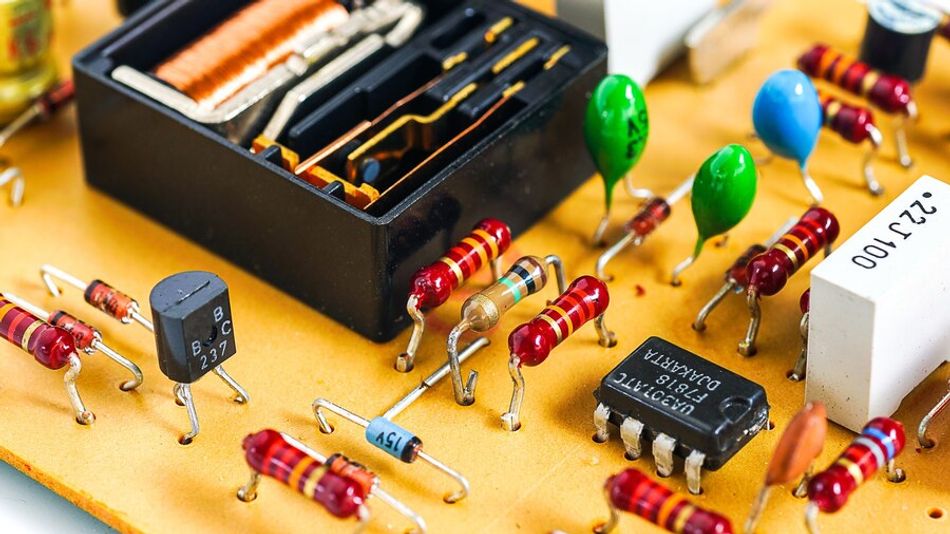
Overview of Filtering Hardware Integrated into Electronic Circuit Design
Key Takeaways
Gain and Impedance Advantages: By combining resistors and capacitors with an amplifier, active filters can boost the amplitude of their pass-band while sharply attenuating unwanted frequencies and offering high input impedance and low output impedance.
Filter Classifications: Low-pass, high-pass, band-pass, band-stop, notch, and all-pass filters allow designers to isolate or suppress specific ranges of frequencies using the same fundamental building blocks.
Topology Trade-Offs: Sallen-Key, multiple feedback (MFB), and state-variable filters each have unique transfer functions, noise behaviour, and component sensitivities; the topology you choose influences performance and stability.
Power and Bandwidth Constraints: Unlike passive filters, active designs depend on a continuous power supply and are limited by the slew rate and gain-bandwidth product of amplifier.
Passive Filter Dominance at High Power/RF: Inductor-based LC or bulk acoustic wave filters handle high currents and multi-gigahertz signals that active op-amp circuits cannot.
Introduction
Modern electronic systems rely on precise signal conditioning to remove unwanted frequencies, reduce noise, and improve overall performance. The active filters achieve this by combining frequency-selective components, such as resistors and capacitors, with amplifying devices like operational amplifiers. Unlike passive networks, they can provide gain, high input impedance, and low output impedance without requiring inductors. This makes them useful in compact and low-frequency circuit designs.
The active filters are commonly classified as low-pass, high-pass, band-pass, and band-stop configurations. Their performance depends on circuit topology, component values, filter order, cutoff frequency, and quality factor. Understanding how active filters are designed also requires examining popular topologies, including Sallen-Key, multiple-feedback, and state-variable circuits. This article explores the main types, key design principles, practical considerations, and performance trade-offs of active filters, while comparing their capabilities, limitations, and applications with passive filters.
What are Filters in Electronic Circuits?
Filters in electronic circuits are networks designed to manipulate the frequency components of an input signal selectively. By attenuating, passing, or amplifying specific frequencies, filters shape the amplitude and phase characteristics of the signal to achieve the desired frequency response.
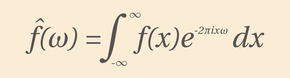
The French mathematician, Joseph Fourier, discovered that any periodic signal can be represented as a sum of sine and cosine waves. The amplitudes of these waves can be determined by analyzing the signal. This means that any periodic signal can be broken down into a set of sine and cosine waves with specific frequencies. These individual frequencies can be manipulated to change the characteristics of the entire signal. Resultantly, filters can be described by their effect on different frequency components of a signal.
The primary goal of filters is to remove unwanted frequency components, such as noise or interference while preserving or enhancing the desired signal components. They are crucial in signal processing applications, as they improve signal quality, prevent aliasing, and maintain the signal within the desired frequency range. Filters help maintain signal integrity and extract relevant information from complex signals in various electronic domains, including telecommunications, audio systems, and data acquisition.
Recommended Reading: How Do Circuit Boards Work: A Comprehensive Guide to the Heart of Electronics
What Are Active Filters?
The active filters are electrical networks that use active components — typically operational amplifiers (op-amps), transistors, or integrated circuits — together with resistors and capacitors to shape the frequency response of a signal. Unlike passive filters, which rely solely on passive components and dissipate energy, active filters draw power from an external supply. This supply enables the amplifier to provide voltage gain and buffering, producing high input impedance and low output impedance so the filter does not load the preceding stage or get loaded by the next stage [7]. In addition to adjusting amplitude, active filters can manipulate phase and improve selectivity without large inductors.
By using an amplifier with negative feedback, active filters maintain predictable transfer functions over a range of load conditions. The basic building blocks are resistors (R) and capacitors (C); inductors (L) are rarely used in active filters because the amplifier can mimic inductive behavior electronically. The high open-loop gain and differential inputs in an op-amp allow designers to implement second-order, third-order, and higher-order filters by cascading multiple stages.
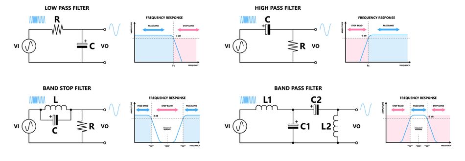
Further, active filters fall into four classic functional categories: low-pass, high-pass, band-pass, and band-stop (notch) filters [6]. Each category controls which frequency bands pass through and which are suppressed. The following sections summarise the various types of active filters before diving into circuit design.
Types of Active Filters
Designers classify active filters based on the frequency ranges they permit or reject. While sophisticated topologies and transfer functions exist, most filter implementations can be categorized into the types below. Each type uses resistors and capacitors around an amplifier to set its cutoff frequency, quality factor (Q), and gain.
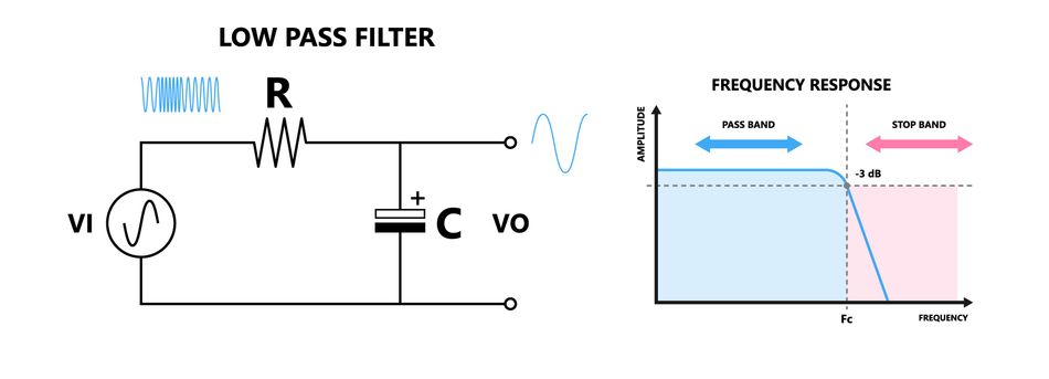
Active Low-Pass Filters
The active low-pass filter passes signals below a specified cutoff frequency and attenuates higher frequencies. It is useful for smoothing data, filtering out high-frequency noise, or preventing aliasing in ADCs. A simple first-order active low-pass can be built from an op-amp in a non-inverting configuration with a single RC network in its feedback loop.
Second-order low-pass filters such as the Sallen-Key topology use two resistors and two capacitors to achieve a steeper roll-off of −40 dB per decade beyond the cutoff frequency. Designers often choose a Butterworth or Chebyshev approximation to optimize flatness or selectivity.
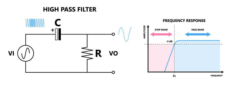
Active High-Pass Filters
The active high-pass filter attenuates frequencies below its cutoff while passing higher frequencies. This filter removes DC offsets and low-frequency drift from sensors or audio signals. A first-order high-pass uses a coupling capacitor in series with the input and a resistor in the feedback path of a non-inverting op-amp.
Higher-order high-pass filters can be realized via Sallen-Key or multiple-feedback topologies, producing a steeper roll-off and more control over quality factor (Q). The design equations mirror those of low-pass filters when component positions are swapped.
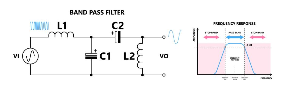
Active Band-Pass Filters
The active band-pass filter allows a range of frequencies centered around a resonant frequency while attenuating frequencies outside this band. Band-pass filters are essential in communication receivers to isolate a desired signal from interfering frequencies and in sensors to select specific vibration frequencies.
The common design uses multiple-feedback topology: one capacitor sets the low-frequency cutoff, and another sets the high-frequency cutoff, while the op-amp provides the necessary gain. The quality factor (Q) of the filter determines how narrow or wide the passband is. Higher Q yields greater selectivity but may lead to peaking and increased sensitivity to component tolerances.
Active Band-Stop (Notch) Filters
The active band-stop filters, or notch filters, reject a narrow band of frequencies while passing frequencies outside this notch. They are used to suppress line-frequency hum (50 Hz or 60 Hz) or specific interference.
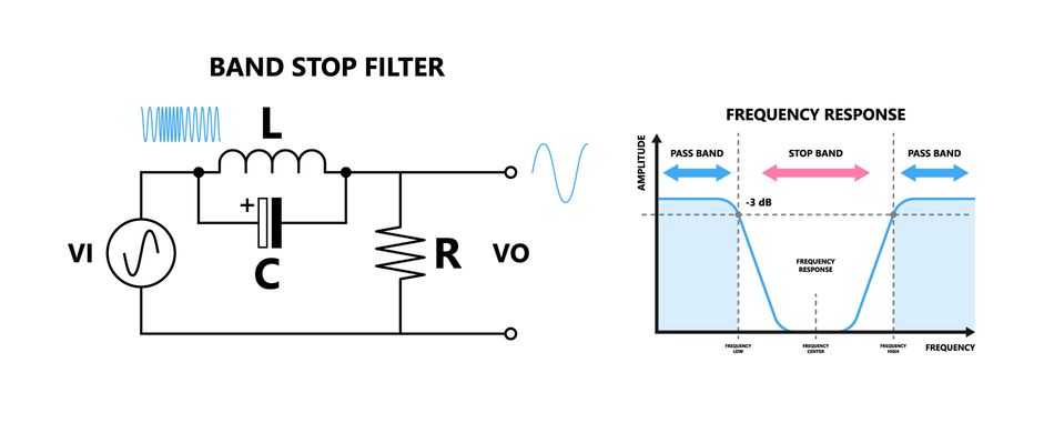
The notch filter combines low-pass and high-pass responses or uses a twin-T network around an op-amp. When designed with an op-amp, the filter can achieve deep attenuation at the notch frequency with adjustable quality factor (Q) and minimal insertion loss. At extremely high radio frequencies, passive approaches like bulk acoustic wave (BAW) filters use piezoelectric resonators to form a notch at several gigahertz for Wi-Fi and 5G applications [9].
Active All-Pass Filters
The active all-pass filter has a unity magnitude response across all frequencies but introduces a controllable phase shift. All-pass sections are cascaded to equalize group delay or to realize phase-lead and phase-lag compensators.
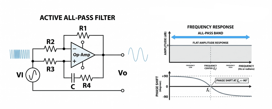
In audio and control systems, all-pass filters correct phase distortion without affecting amplitude. The typical all-pass stage uses an op-amp in an inverting configuration with RC networks in both input and feedback paths. The amount of phase shift depends on the ratio of resistors and capacitors.
Recommended Reading: Low Pass Filter vs High Pass Filter – Theory, Design, and Applications
Components Used in Active Filters
The fundamental components in active filters are resistors, capacitors, and an amplifier. The amplifier may be an operational amplifier (op-amp), a discrete transistor, or an integrated active-filter chip. Op-amps are the most common because they offer high open-loop gain, differential inputs, and well-defined feedback behavior. Once used with a DC power supply, the op-amp provides signal gain and buffering so the filter exhibits high input impedance and low output impedance [9].
Passive components set the poles and zeros of the filter. Resistors determine time constants and damping. Capacitors store and release energy, thereby creating frequency-dependent reactance. Inductors are seldom used because they are bulky, introduce magnetic coupling, and require shielding; instead, active circuits emulate inductors using op-amp-based gyrators. Integrated filter chips combine active and passive elements on a single die for high-frequency or space-constrained applications.
The component tolerances and temperature coefficients strongly influence filter accuracy. Metal-film resistors and C0G/NP0 capacitors with low drift are preferred for precision filters. In high-frequency active filters, the parasitic inductance and capacitance of the PCB layout become significant, requiring careful design.
Active Filter Circuit Configurations and Transfer Functions
Multiple circuit topologies implement active filters. Each topology yields a different transfer function, noise characteristic, and sensitivity to component values. The most common configurations are the Sallen-Key, multiple-feedback (MFB), and state-variable filters.
Sallen-Key (Voltage-Controlled Voltage Source)
The Sallen-Key configuration is a simple two-pole topology where an op-amp operates as a voltage follower or non-inverting amplifier. 2 resistors and 2 capacitors form an RC network whose output is fed back to the non-inverting input of the op-amp. The op-amp isolates the RC section from the load and provides gain. The unity-gain Sallen-Key low-pass transfer function is:

where s is the complex frequency variable. By choosing equal-valued capacitors (C₁ = C₂ = C) and resistors (R₁ = R₂ = R), the cutoff frequency is fc = 1/(2πRC) and the damping ratio controls the Q. Once configured for higher gain, the op-amp becomes a non-inverting amplifier whose closed-loop gain adjusts the quality factor of the filter.
For a high-pass Sallen-Key filter, the resistors and capacitors swap positions in the RC network, yielding a numerator that cancels low-frequency components. Sallen-Key designs offer low component sensitivity and require only one amplifier per stage, making them popular for audio and instrumentation [1].
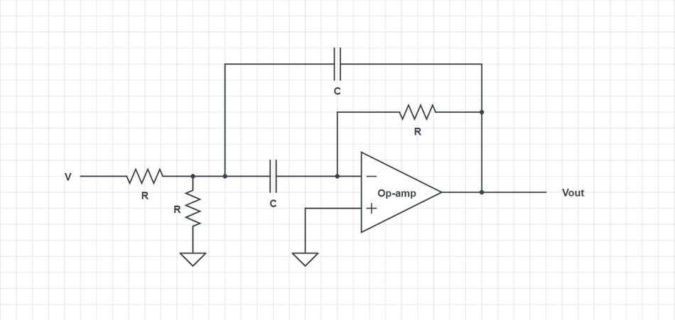
Multiple-Feedback (MFB)
The multiple-feedback topology uses the op-amp in an inverting amplifier configuration. The input signal and feedback network incorporate multiple RC sections that define both the high-pass and low-pass behaviors simultaneously. The general transfer function for a second-order MFB low-pass filter is:
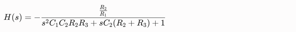
where R₁ sets the input attenuation, R₂ and R₃ form the feedback network, and C₁, C₂ set the poles. The negative sign indicates an inversion of phase. Designers adjust the ratio R₂/R₁ to set the pass-band gain of the filter. The MFB topology offers better stop-band attenuation and better control of Q than the Sallen-Key, but its noise performance can be worse because the input noise of the op-amp is amplified in the inverting mode.
To implement a band-pass filter, the MFB network uses a series capacitor at the input and a parallel capacitor in the feedback path. The resulting transfer function has a second-order denominator and a numerator proportional to s, producing zero gain at DC and at high frequencies but peak gain at the center frequency.
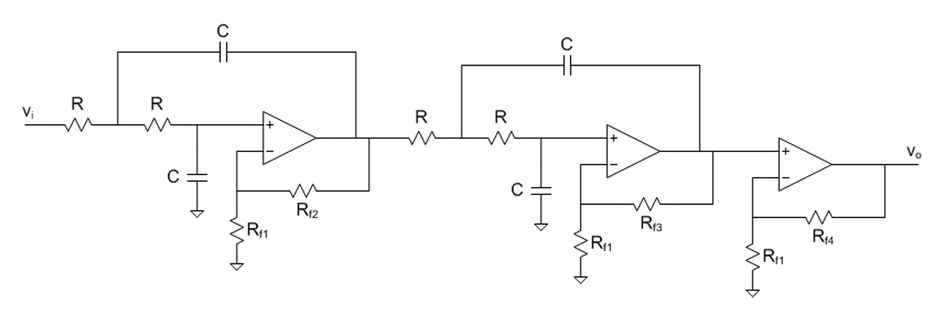
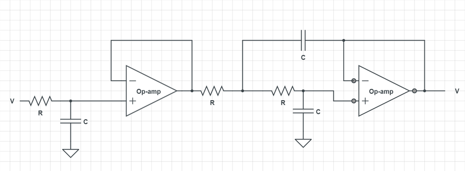
State-Variable (Kerwin-Huelsman-Newcomb)
The state-variable or Kerwin-Huelsman-Newcomb (KHN) filter uses three op-amps to simultaneously produce low-pass, band-pass, and high-pass outputs from the same circuit. The topology integrates the state-space variables of the differential equation in the filter. The basic circuit consists of two integrators cascaded with an inverting summer.
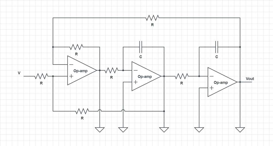
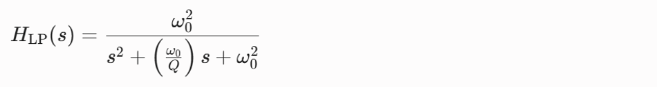
The transfer functions are:
Low-Pass Output:
Band-Pass Output:
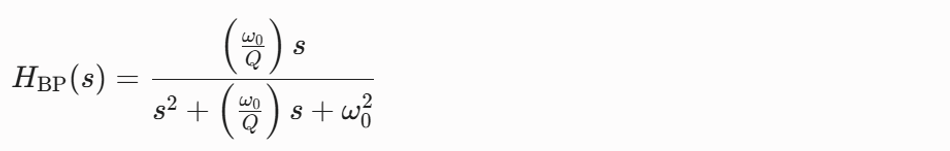
High-Pass Output:
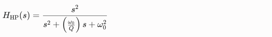
where ω₀ is the natural frequency (2π·fc). This topology allows independent adjustment of centre frequency and Q by choosing appropriate resistor and capacitor values. Because it uses three op-amps, it offers excellent performance with precise gain and frequency stability, but the circuit is more complex and power-hungry.
Other Topologies
The additional active filter topologies include biquad filters, universal filter blocks, and gyrator-based circuits:
Biquad Filters implement a second-order transfer function using a pair of integrators and summers; they are common in digital filter emulation.
Universal Filter Blocks allow designers to select low-pass, high-pass, band-pass, or notch responses via jumpers or switches.
Gyrator Circuits emulate inductance using capacitors and op-amps, enabling the realization of active LC filters without physical inductors.
Active Filter Stability and Component Selection
Stability refers to the ability of a filter to maintain its intended transfer function under variations in component values, load conditions, and amplifier characteristics. In active filters, the gain-bandwidth product (GBW) and slew rate of the amplifier limit the highest frequency at which the circuit can operate with predictable gain and phase. The op-amp with a GBW of 10 MHz cannot realize a high-Q filter at 1 MHz because the required gain at the resonant frequency would fall outside its bandwidth. Designers must choose an amplifier with a GBW at least ten times the highest frequency of any filter.
The component tolerance is another source of variability. The Q of a Sallen-Key or MFB filter is highly sensitive to resistor ratios. To achieve a Butterworth response (maximally flat), resistor values may need to be matched to within ±1%. Capacitor tolerances and temperature coefficients also affect the cutoff frequency. [5] Using precision resistors and NP0 or C0G capacitors reduces drift. In high-order filters, cascading multiple second-order sections prevents component interactions that might destabilize the overall response.
Then, layout considerations become critical as frequencies increase. Parasitic capacitance and inductance of traces, vias, and component leads can shift pole frequencies. Keep signal traces short, use ground planes to reduce impedance, and avoid coupling between input and output paths. A well-regulated power supply with adequate decoupling prevents noise or ripple from coupling into the filter. The choice of amplifier topology also influences noise. Low-noise op-amps and proper resistor values minimize Johnson noise and current noise.
The negative feedback stabilizes active filters but can introduce phase shifts that lead to oscillation if loop gain approaches unity at an unintended frequency. Designers should analyze the loop-gain Bode plot to ensure sufficient phase margin. The compensation networks or damping resistors can improve stability.
Recommended Reading: Understanding Noise Sources from GHz to nHz and How to Control Them
Filter Approximation Methods
The theoretical frequency response of a filter is described by its transfer function, but designers must choose how steep the roll-off is, how flat the pass-band should be, and whether ripple is acceptable. The approximation methods provide standard polynomials to shape the magnitude response.
Butterworth: Maximally flat pass-band with no ripple. The magnitude response is |H(jω)| = 1 / √(1 + (ω/ωc)^(2n)) for an n-th order filter. Commonly used when a smooth response is more important than steep attenuation [2].
Chebyshev Type I: Allows equal ripple in the pass-band in exchange for a steeper roll-off at the cutoff frequency. The ripple amplitude and order determine the attenuation slope. The transfer function incorporates Chebyshev polynomials of the first kind.
Chebyshev Type II (Inverse Chebyshev): Ripple appears in the stop-band rather than the pass-band, resulting in a flat pass-band but ripple above the cutoff. Less common in active filters.
Elliptic (Cauer): Equal ripple in both pass-band and stop-band, yielding the steepest roll-off for a given order. Requires more stringent component matching and produces higher Q values.
Bessel: Optimizes group delay rather than magnitude; preserves waveform shape by minimizing phase distortion [6]. Useful in audio and data communications where transient response matters.
Designers implement these approximations by selecting component ratios that produce the desired pole and zero locations. Tables and software tools provide normalized component values for Butterworth, Chebyshev, Elliptic, and Bessel filters of various orders. The higher order results in a steeper roll-off but increases complexity and component sensitivity.
Computer-Aided Design Tools
Modern filter design relies heavily on computer-aided design (CAD) tools. Engineers use SPICE simulators (LTspice, Multisim) to verify the time-domain and frequency-domain behavior of active filter circuits. These tools model op-amp limitations, parasitic components, and noise. MATLAB and Python libraries such as SciPy provide functions to compute filter coefficients for Butterworth, Chebyshev, or Elliptic responses and to plot magnitude and phase responses. Web-based calculators can quickly generate component values for Sallen-Key or MFB topologies. Integrated circuit manufacturers offer design tools that interface directly with their op-amp models, enabling the prediction of distortion, noise, and stability.
Keysight ADS stands out as a powerful Electronic Design Automation (EDA) tool specifically designed for RF and microwave circuit design and simulation. It boasts integrated electromagnetic simulation capabilities through its Momentum tool, allowing engineers to analyze critical factors like signal integrity, power integrity, and electromagnetic interference (EMI) within their designs. Keysight ADS provides an environment where engineers can design and optimize filters while considering their performance within the larger context of the entire system.
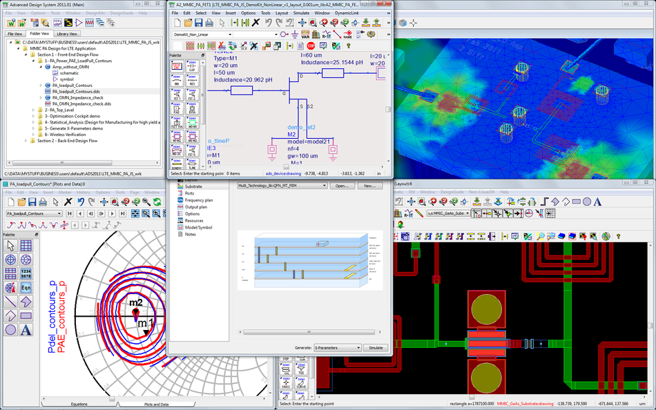
The graphical filter-synthesis packages allow designers to drag and drop components, select approximations, and automatically generate schematic diagrams and bills of materials. These tools often integrate with PCB layout software to help manage parasitic effects. While CAD tools greatly streamline the design process, understanding the underlying theory remains essential for verifying results and troubleshooting unexpected behavior.
Passive Filters: A Brief Comparison Reference
Although active filters dominate low-frequency and mid-frequency signal conditioning, passive filters remain indispensable in many contexts. This section condenses passive-filter theory into a concise reference, highlighting components, typical configurations, stability considerations, and when to choose a passive solution.
Components and Energy Storage
Passive filters use resistors, capacitors, and inductors. Resistors dissipate energy, capacitors store electric charge, and inductors store magnetic energy. Unlike active filters, passive filters require no external power supply and cannot amplify signals [8]. Inductors allow passive filters to handle high currents and high frequencies; they are used in power supplies, RF front ends, and impedance-matching networks. Inductors are bulky, expensive, and suffer from core losses and electromagnetic coupling. Capacitor-based RC filters avoid inductors but offer limited roll-off (−20 dB/decade per order) [4].
Bulk Acoustic Wave (BAW) filters exemplify passive components that work at multi-gigahertz frequencies. These devices use a piezoelectric material excited by an alternating electric field; the acoustic waves create resonances that sharply attenuate unwanted RF bands. BAW filters operate between 2–6 GHz and appear in Wi-Fi routers, 5G smartphones, and automotive radar systems [9]. Such high-frequency operation is beyond the reach of op-amp-based active filters due to bandwidth limitations.
Circuit Configurations Overview
Passive filters can be implemented in several configurations. RC low-pass and high-pass filters are simple first-order networks used for audio tone control, sensor decoupling, and anti-aliasing at lower frequencies. LC filters combine inductors and capacitors to form resonant circuits. L-section or π-section low-pass filter uses an inductor and capacitor to achieve a sharp roll-off and low insertion loss. Ladder networks, using alternating series inductors and shunt capacitors, realize higher-order filters with high Q. Diplexers and duplexers incorporate passive filters to split or combine signals in radio systems. Ferrite beads and feed-through capacitors are passive elements used for electromagnetic interference suppression.
Stability, Losses, and Layout
Passive filters are inherently stable because they do not employ feedback. Their transfer functions depend only on the component values and operate over a wide range of load impedances. Passive filters introduce insertion loss: energy is dissipated in the resistive elements and component ESR. At high power levels, the resistance and core saturation of the inductor cause additional losses and distortion. Passive filters are also sensitive to component tolerances and parasitics. The winding capacitance of inductors and the equivalent series resistance of capacitors shift the cutoff frequency and Q. Proper layout and shielding reduce magnetic coupling between inductors.
In contrast to active filters, passive networks do not generate noise beyond thermal noise. Because they lack gain, they cannot buffer between stages; the source and load impedances must be matched to avoid loading effects. In radio transmitters, passive matching networks maximise power transfer; active filters would degrade efficiency because they cannot handle high voltages and currents.
When to Choose Passive Filters?
Passive filters are appropriate when the design must operate at high power or very high frequency, where op-amp limitations make active designs impractical. They are also used when the circuit must be highly reliable and simple, with no power-supply dependence. Power converters use LC filters to smooth switching waveforms; RF front ends use BAW, surface acoustic wave (SAW), or LC band-pass filters to select channels; and audio crossover networks use passive filters to distribute power between speakers.
The absence of active components reduces cost and increases robustness. When high gain, precise cutoffs, or tunability are required at low to medium frequencies, active filters offer superior performance.
Factors Affecting Filter Performance
Several factors impact the real-world performance of active filters:
Component Tolerances: Variations in resistor and capacitor values shift pole frequencies and Q. Precision components with low temperature coefficients minimize drift.
Amplifier Limitations: Op-amp finite gain-bandwidth product, slew rate, input bias current, and output drive capability restrict the achievable frequency range and dynamic range.
Power-Supply Noise: Noise and ripple from the power supply can modulate the filter's transfer function. Decoupling capacitors and low-noise regulators mitigate this issue.
Parasitic Elements: PCB trace resistance, capacitance, and inductance introduce additional poles and zeros. Grounding and layout best practices reduce these parasitics.
Thermal and Environmental Factors: Temperature changes affect component values; humidity can alter the dielectric constant of capacitors. Robust design accounts for worst-case operating conditions.
Design Challenges and Trade-Offs
Designing active filters involves balancing multiple trade-offs. Higher-order filters provide steeper roll-off but require more components and op-amps, increasing cost, complexity, and power consumption. Achieving a high Q with a Sallen-Key or MFB topology may result in peaking and increased sensitivity to component tolerances. Lowering the Q broadens the pass-band and improves stability but reduces selectivity. Active filters also generate noise: the input voltage noise, current noise, and resistor thermal noise of an op-amp accumulate and may limit the dynamic range [3].
Another challenge is the interaction between filter stages. Cascading multiple active stages can load the input impedance of the next stage, altering the overall response. Buffering stages or designing for high input impedance and low output impedance mitigate this issue. Designers must also consider linearity; high-amplitude signals can drive the op-amp into saturation or slew-rate limiting, causing distortion. Proper selection of amplifier type, supply voltage, and headroom is critical. Finally, designers need to test prototypes across process, voltage, and temperature variations to ensure consistent performance.
Active Filter Applications
Because active filters provide gain and can drive low-impedance loads, they are widely used in instrumentation, communications, and audio. In instrumentation systems, active filters condition sensor signals before they are digitized; for example, they attenuate noise and aliasing in strain-gauge or thermocouple circuits. Op-amp-based difference amplifiers (also known as instrumentation amplifiers) combine gain and filtering to reject common-mode noise and amplify differential signals [9]. In audio equipment, active filters implement tone control, crossover networks, and equalisation.
The communication equipment uses active band-pass filters to select narrow channels and notch filters to suppress interference. For low-power wireless systems, active filters complement passive RF filters; the passive filter handles gigahertz-frequency front-end tasks, while an active filter shapes baseband or intermediate frequencies. In data converters, active antialiasing filters remove components above half the sampling frequency. Active filters also appear in oscillators and waveform generators, where a phase-shift network and an amplifier sustain oscillation at a desired frequency. Finally, active filters are embedded in integrated circuits for signal conditioning inside smartphones and wearables.
Conclusion
The active filters are versatile tools for shaping the frequency response of electronic signals. By combining resistors and capacitors with an amplifier, they provide gain, controllable cutoffs, and high input impedance, enabling precise filtering and buffering at low and medium frequencies. Topologies such as the Sallen-Key, multiple-feedback, and state-variable filters offer different trade-offs in complexity, noise, and component sensitivity. Approximation methods like Butterworth, Chebyshev, and Elliptic allow designers to tailor the magnitude response. Active filters require power, and their performance is limited by the amplifier's bandwidth and noise. Passive filters, on the other hand, excel at high power and high frequency and remain critical in RF and power applications. Understanding both active and passive approaches empowers engineers to make informed choices for a given application. With careful component selection, stable circuit design, and the aid of CAD tools, active filters can meet demanding specifications and deliver clean, well-conditioned signals in a wide range of systems.
Frequently Asked Questions
Q. What is the difference between an active filter and a passive filter?
A. The active filter uses active elements, such as an op-amp, with resistors and capacitors to provide gain, buffering, and frequency shaping. On the other hand, a passive filter uses only passive components, needs no power supply, and cannot amplify the input signal.
Q. What is the most common active filter topology?
A. The Sallen-Key circuit is the most common active filter topology for second-order low-pass and high-pass designs. It uses one op-amp and an RC network, offers a tunable cutoff frequency, and can be cascaded to create higher-order responses.
Q. Why avoid inductors in active filters?
A. Inductors are bulky, expensive, and suffer from electromagnetic coupling. Active filters emulate inductors using op-amps and capacitors, achieving similar responses without large magnetics. This emulation is feasible at low and medium frequencies but not at RF.
Q. How do I select the order and approximation for my filter?
A. Choose the filter order according to the required roll-off and acceptable ripple. Then choose the type of filter approximation: Butterworth filter for flat response, Chebyshev filter for steeper attenuation, or Elliptic filter for maximum selectivity with ripple.
References
[1] Brahms. Chapter 12 - Active Filters [Cited 2026 June 30]; Available at: Link
[2] Open University. 2.5: Normalised First-Order Low-Pass Filters [Cited 2026 June 30]; Available at: Link
[3] CTMS. Extras: Designing Lead and Lag Compensators [Cited 2026 June 30]; Available at: Link
[4] Electronics Tutorials. Passive Band Pass Filter [Cited 2026 June 30]; Available at: Link
[5] Engineer LibreTexts. 11.3: The Use and Advantages of Active Filters [Cited 2026 June 30]; Available at: Link
[6] James M. Fiore. Operational Amplifiers & Linear Integrated Circuits — Theory and Application [Cited 2026 June 30]; Available at: Link
[7] Test & Measurement Tips. Measuring Active and Passive Filters [Cited 2026 June 30]; Available at: Link
[8] GBC Electronics / ETcourse. Differences Between Active and Passive Filters [Cited 2026 June 30]; Available at: Link
[9] RF Page. Bulk Acoustic Wave (BAW) Filters: The Filtering Solution for 5G and Beyond [Cited 2026 June 30]; Available at: Link
in this article
1. Key Takeaways2. Introduction3. What are Filters in Electronic Circuits?4. What Are Active Filters?5. Types of Active Filters6. Components Used in Active Filters7. Active Filter Circuit Configurations and Transfer Functions8. Active Filter Stability and Component Selection9. Filter Approximation Methods10. Computer-Aided Design Tools11. Passive Filters: A Brief Comparison Reference12. Factors Affecting Filter Performance13. Design Challenges and Trade-Offs14. Active Filter Applications15. Conclusion16. Frequently Asked Questions17. References