Optimizing PCB Space and System Reliability with OMRONs G3VM Solid-State MOS FET Relays
Solid-state MOS FET relays offer compact size, fast and stable switching, low power use, and long service life. With diverse package options and strong isolation, they help engineers build reliable, space-efficient, and maintenance-free electronic systems.

18 Dec, 2025. 5 minutes read
Mechanical relays are some of the most widely used electronic components and an essential part of the electronics engineering industry. Although popular, they come with several limitations: large electromagnetic coils, contact wear, audible clicking noise, switching characteristics limited by mechanical movement, and more.
Solid-state MOS FET relays offer a solution to these problems by replacing the mechanical motion with semiconductor switching. They come with no physical contacts, stable performance across a range of loads, and long operating lifetimes, all in more compact packages.
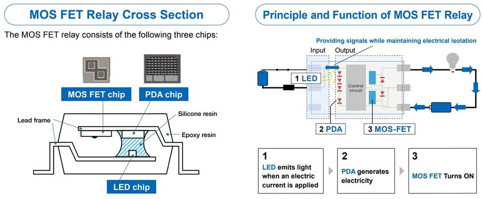
Internal Architecture and Operating Principle
Mechanical relays come with a small internal coil, which, when energized with a low-power control signal, turns into an electromagnet and moves the contact on the output side to snap open or close, thereby controlling the flow of electricity.
Solid-state MOS FET relays, on the other hand, operate through optical coupling. The input stage uses an LED that turns on with a small signal current and triggers a photodiode array, which converts the optical signal into a voltage and drives a pair of MOS FETs on the output side. The MOS FETs are connected in a back-to-back configuration, enabling bidirectional control and allowing the relay to switch both AC and DC systems.
Other alternatives exist, but they lack flexibility. Phototransistor couplers are unidirectional, and phototriac couplers work with AC but stay latched until current reaches zero, preventing DC switching. MOS FET relays can switch for both AC and DC systems, making them more versatile and suitable for mixed signal systems.
Performance Metrics
The benefits of MOS FET relays become clearer when comparing their behavior with mechanical relays across different performance parameters:
Table 1: Key differences between mechanical relays and MOS FET Relays
Parameter | Mechanical Relay | MOS FET Relay (e.g., OMRON G3VM) |
Switching speed | 3-5 ms | ~0.2 ms (typical) |
Operating life | 10⁵-10⁶ operations | No contact wear; practically unlimited switching life |
Input drive current | ≥ 40 mA (coil) | ~0.2-15 mA (LED-driven) |
Package volume | High (coil + contacts, often >400 mm³) | Very low (can go as low as 3-4 mm³) |
Audible noise | Yes (mechanical actuation) | None (solid-state switching) |
These differences have practical design implications. Faster switching improves signal fidelity, a critical aspect in applications where precise timing control is a necessity. A significantly lower current draw reduces the power consumption and heating. Exclusion of mechanical contacts offers a consistent switching characteristic over time, preventing failures caused by factors like wear or oxidation. Finally, the compact package options allow designers to reduce board size or accommodate more components.

These attributes make MOS FET relays the right choice for applications that require a predictable behavior, fast dynamic response, and maintenance-free operation over a long period.
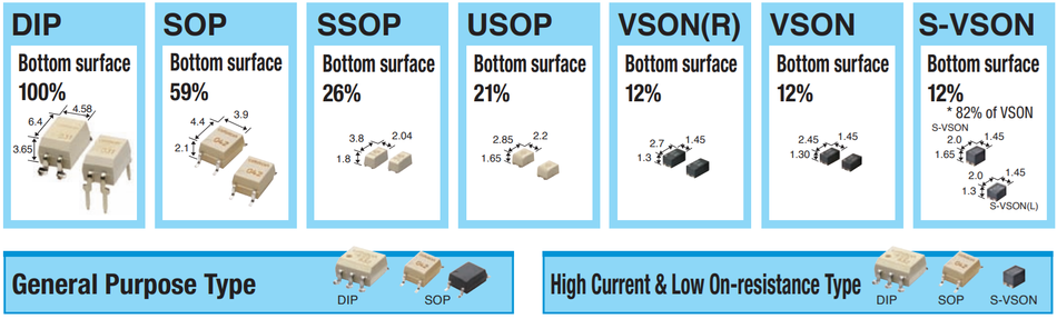
Space Optimization Through Advanced Packaging
Probably the strongest advantage of solid-state MOS FET relays is the range of compact package options that reduce the required PCB footprint compared to mechanical relays. Traditional relays must come with coils, armatures, and contacts, limiting how small they can practically become. In contrast, MOS FET relays use optical coupling and semiconductor switching that can scale efficiently with modern IC packaging processes.
Reliability and Longevity Engineering
The improved reliability of MOS FET relays comes directly from their ability to switch without making mechanical contact. Because there are no repetitive opening and closing operations, several common failure scenarios associated with electromechanical relays are eliminated. Issues such as oxidation, arcing, pitting, and particulate transfer are nonexistent.
The metal contacts within electromechanical relays experience changes in resistance during operation. This is caused by factors such as heat or over time, due to wear, oxidation, or contamination. For sensitive applications like measurement, testing, and sensing, this resistance drift can degrade the signal integrity, leading to inaccuracies or even malfunctions. They also suffer from contact bounce, just like pushbuttons.
Leakage performance is another key advantage of MOS FET relays. Most MOS FET relays exhibit low off-state leakage currents, often in the range of nanoamperes, helping preserve accuracy in high-impedance analog circuits. The solid-state design inherently eliminates coil-induced transients, eliminating the need for an external snubber circuit and simplifying the design further.
While operating temperature ratings vary across MOS FET relays, industry-leading products like the G3VM lineup by OMRON support ranges up to 80°C and 110°C, with certain variants designed to operate even up to 125°C.
These characteristics of MOS FET relays drastically improve their mean time to failure (MTTF) compared to their electromechanical counterparts.
Broad Lineup for Diverse Applications
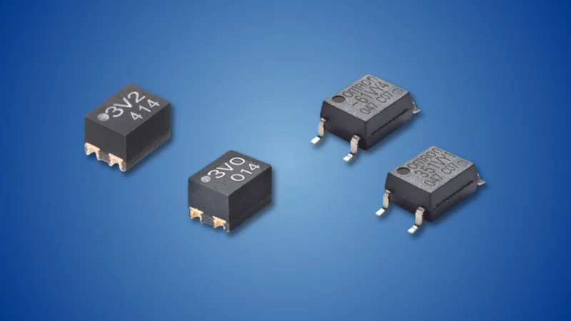
OMRON G3VM is a family of solid-state relays that cover a wide range of electrical and mechanical requirements, making it very versatile. Instead of a one-size-fits-all approach, OMRON offers a lineup that is organized into categories that address specific engineering needs.
General-purpose lineup covers a range of specifications, with different models offering load voltages up to 400 V and currents up to 1 A. They are suitable for signal routing, logic-level switching, and mixed analog-digital circuits. Engineers looking for a balance of size, performance, and cost consider these as their top choice.
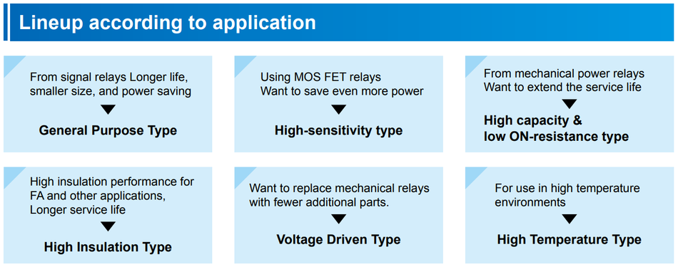
For power-constrained applications, engineers can pick high-sensitivity types that reduce LED trigger current to as low as 0.2 mA. These are ideal for battery-powered devices where every mW of power is a luxury.
High-capacity and low ON-resistance variants are available, with certain models offering an ON-state resistance of around 0.022 Ω, and others supporting continuous currents up to 5 A. High-insulation types, which offer input-output dielectric strength up to 5 kVrms are also available. Finally, the product line also includes high-temperature variants for operation in environments with extraordinary thermal demands.
Across these categories, both current-drive and voltage-drive configurations are available. The purpose behind introducing these variants is to let engineers select a relay tailored to their application rather than adapting the design to suit the relay.
Selecting the Right Solid-State Relay with OMRON’s Design-Support Ecosystem
Typically, the process of selecting the relay begins by identifying the required load voltage range and continuous load current, since these parameters help determine the minimum relay ratings. Next up, the choice is made between normally open or normally closed configurations, depending on which state the relay would be in most of the time during its operation.
Once these baseline specifications are finalized, engineers review the device-level characteristics such as ON-resistance, OFF-state leakage, capacitance, and isolation voltage limits to ensure compatibility with their circuit performance targets.
OMRON provides a detailed parametric selection page to simplify and facilitate this process. Engineers can filter the products by load voltage, current, packaging, and switching performance. Each device comes with detailed datasheets and 3D CAD models, SPICE/LTspice simulation data, supporting both mechanical layout planning and circuit-level verification.
Compliance is also an important consideration, and hence, all models in the G3VM family comply with RoHS and REACH, and most of them come with UL certifications to help manufacturers meet the regulatory or market-specific requirements.
In addition to all the technical documentation and support, OMRON’s long-term production consistency helps ensure a stable supply over the lifespan of a project.
Conclusion
Solid-state MOS FET relays offer clear advantages in size, performance, and long-term reliability compared to traditional mechanical relays. Combined with OMRON’s design-support resources, simulation tools, and consistent manufacturing, the G3VM MOS FET relay family becomes an attractive choice for designers looking to add reliable switching to their compact electronic systems.