What Is a Load Cell? Working Principle, Types, and Selection Guide
This article explains how load cells work, the main types, what accuracy specs and OIML/NTEP classes mean, and best practices for sizing, wiring, and installation.

20 Aug, 2026. 17 minutes read
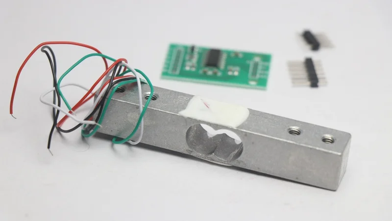
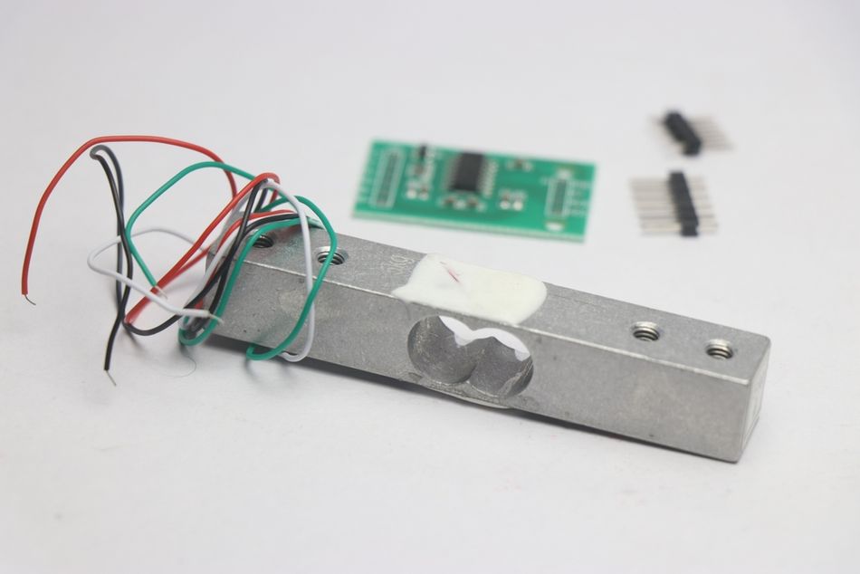
Load Cell Module with Amplifier in the Background with Unsoldered Pins
Key Takeaways
Transduction Principle and Low Output – A strain gauge load cell converts force into strain in a machined spring element, then into a change in electrical resistance read by a Wheatstone bridge. Full-scale output is typically 2 mV/V, so a 5 V excitation gives only 10 mV of signal.
Verification Interval Classification – Accuracy classes are defined by the number of load cell verification intervals, not by a single percentage. OIML R 60-1:2021 caps Class C at 10,000 intervals and Class B at 100,000.
Capacity Utilization Effects – Utilization dominates real accuracy. Dropping from 80% to 20% of rated capacity improved nonlinearity by a factor of 7 and hysteresis by a factor of 8 on one 500 kg test cell.
Creep Standard Discrepancies – Creep tolerances differ sharply between standards: 62% of load cells that passed the NTEP 60-minute creep test failed the OIML 30-minute tolerance in a NIST study of 65 cells.
Mechanical Installation Factors – Most field accuracy problems are mechanical, not electrical. Side loads, stay rods, piping, and thermal gradients introduce errors that no calibration can remove.
Introduction
The load cell is a precision transducer that converts an applied force into a measurable electrical signal. You will find load cells anywhere force or mass has to be quantified: truck scales, tank and silo weighing systems, material testing machines, robot wrists, bathroom scales, and laboratory balances.
The dominant technology is the bonded foil strain gauge load cell, and it has held that position for decades because it combines high accuracy, good stability, and low cost. Other principles exist, and legal metrology explicitly allows them. OIML R 60-1:2021 states that the term load cell "is not limited to any particular type of technology or design principle," and names pressure-based (hydraulic, pneumatic), vibratory frequency, and magnetic force variants alongside strain gauge designs.
This guide covers load cell operating principles, type selection, capacity sizing, datasheet analysis, compliance certifications, and proper installation practices for optimal performance.
How a Strain Gauge Load Cell Works
The Spring Element Converts Force to Strain
Every strain gauge load cell starts with a precision-machined metal body, called the spring element or flexure. Its geometry is designed so that a specific region deforms elastically and repeatably in proportion to the applied load.
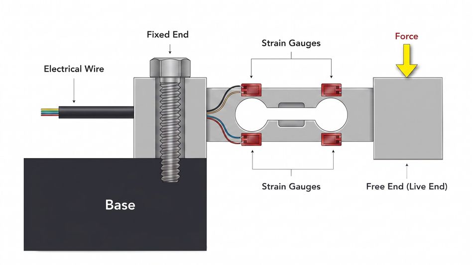
The material choice sets both performance and cost. VPG lists four common spring element materials: tool steel (usually nickel-plated for corrosion protection), stainless steel, aluminium, and copper beryllium alloy. [1] Stainless steel is the default where washdown, corrosive process media, or hygienic requirements apply, and it is what you will find on most hermetically sealed industrial cells.
The performance of a load cell depends on its ability to deflect repeatably. It is not a solid block of steel, and treating it as structural support is a common design error.
The Wheatstone Bridge Turns Strain into an Electrical Signal
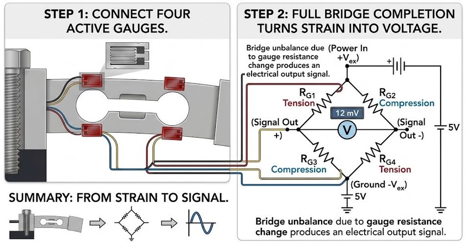
Strain gauges are foil conductors laid out in a serpentine pattern and bonded to the spring element. Stretching the foil increases its electrical resistance; compressing it decreases it.
The relationship is set by the gauge factor:
dR/R = GF x strain
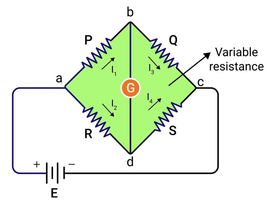
For metal foil strain gages, the gauge factor is nominally 2.0. The resulting resistance change is tiny. The typical 350-ohm gauge changes by only about 0.0007 ohms per microstrain. [2] Four gauges wired as a Wheatstone bridge convert that resistance change into a differential voltage:
V(out) = K x V x strain x N / 4
where K is the gauge factor, V the excitation voltage, and N the number of active bridge arms. N is 4 for a bending beam load cell, roughly 2.6 for a tension or compression column, and 1 for single-gauge stress analysis. The full bridge maximizes sensitivity and linearity, which is why virtually all commercial load cells use one.
The bridge output is small by any standard. The sensitivity is 0.5 microvolts per volt of excitation per microstrain at a gauge factor of 2.0, so even at 10 V excitation you get only 5 microvolts per microstrain.
The common bridge resistances are 120 ohms, 350 ohms, and 1000 ohms. [3] Higher bridge resistance reduces excitation current and self-heating, which matters for battery-powered instrumentation.
Why Is Output Specified in mV/V?
Because bridge output scales with excitation, load cell sensitivity is specified as output per volt of excitation at rated capacity, in mV/V. Typical values range from 1 mV/V to 3 mV/V, with 2 mV/V as the industry norm.
Texas Instruments gives the worked case: a 2 mV/V load cell excited at 5 V produces a full-scale differential output of just 10 mV. [4] Load cell signals are generally under ±20 mV, which sets the requirements for everything downstream.
Sensitivity is a ratio, so the same cell at 10 V excitation gives 20 mV. Raising excitation improves signal-to-noise but increases self-heating, and the maximum excitation voltage in a datasheet is a thermal limit.
Temperature Compensation Inside the Cell
The elastic modulus of steel changes with temperature, so an uncompensated bridge would drift on both zero and span. The manufacturers compensate internally with two mechanisms:
The temperature-dependent wire inside the bridge corrects the zero offset for non-homogeneous changes in component resistance and steel elasticity.
The modulus resistors in excitation lines correct the span for the varying elasticity modulus. These are built like strain gauges and bonded to the element so they track its temperature quickly.
This compensation works when the cell is thermally stabilized. It does not protect you against temperature gradients, which is a separate and much harder problem covered below.
Recommended Reading: Wheatstone Bridge: Principles, Configurations, and Signal Conditioning for Precise Measurements
Types of Load Cells and Where Each Fits
The type selection depends on the direction of loading, the available envelope, capacity, and how well you can control load introduction.
Bending Beam Load Cells
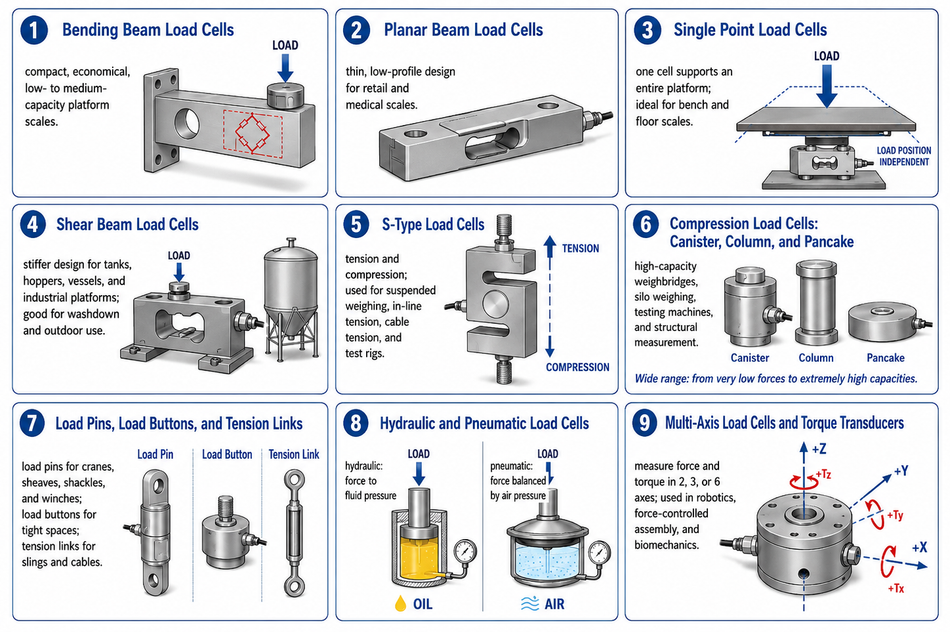
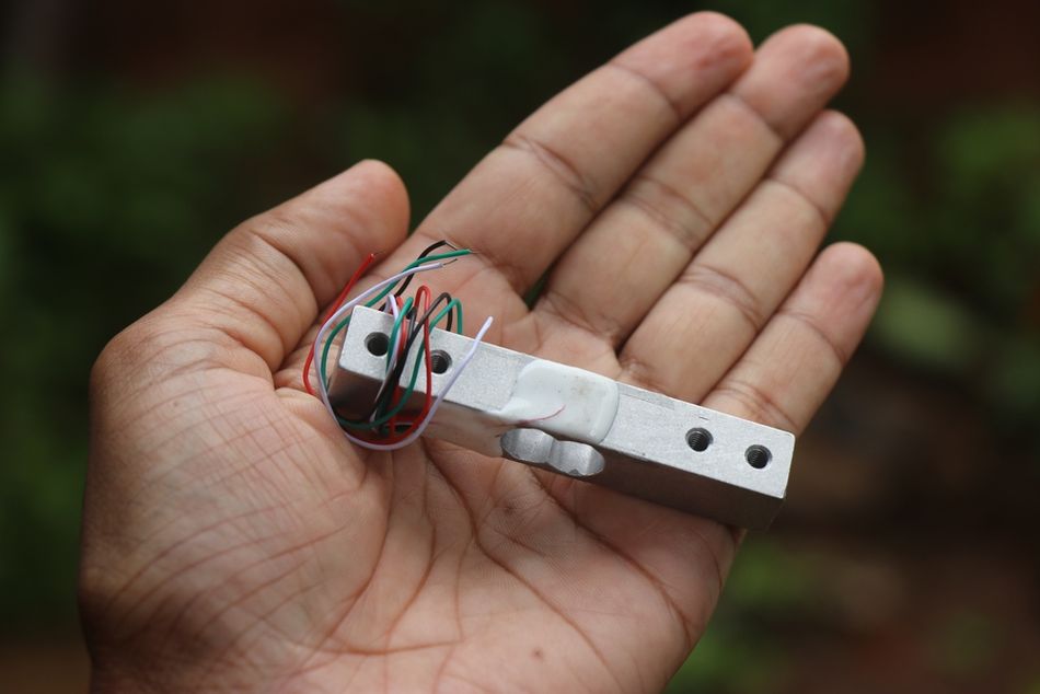
Bending beam load cells measure strain created on the upper and lower surfaces of a cantilevered beam. They are compact, economical, and widely used in low- to medium-capacity platform scales. Double-bending beam designs provide higher capacities in a similar footprint.
Planar Beam Load Cells
Planar beam load cells use a thinner, low-profile geometry and are particularly useful where installation height is restricted, including retail and medical weighing systems. Beam designs also respond relatively quickly to temperature changes and generally show low sensitivity to inclined loading.
Single Point Load Cells
Single point load cells are designed so that one cell supports an entire platform, with output essentially independent of where the load sits on that platform. They are the standard choice for bench and floor scales up to roughly platform sizes the cell is rated for. The corner load correction is built into the machining, so you do not need four cells and a summing junction box.
Shear Beam Load Cells
Shear beam load cells measure shear strain in a machined web rather than surface bending strain. That makes them stiffer, less sensitive to the exact point of load application, and better behaved under side load than bending beams. They are widely used for tank, hopper, vessel, and industrial platform weighing. Hermetically sealed and laser-welded versions are available for washdown, outdoor, and other demanding environments.
S-Type Load Cells
The S-type load cell, also called an S-beam because of its squared-off S shape, handles both tension and compression. The S-beam geometry puts the strain gauges in the central web where strain is highest. They are the usual answer for suspended weighing, in-line tension measurement, cable tension, and low- to medium-capacity test rigs. Their weakness is sensitivity to off-axis loading: an S-beam load cell loaded through a rigid connection rather than rod ends and swivels will read badly.
Compression Load Cells: Canister, Column, and Pancake
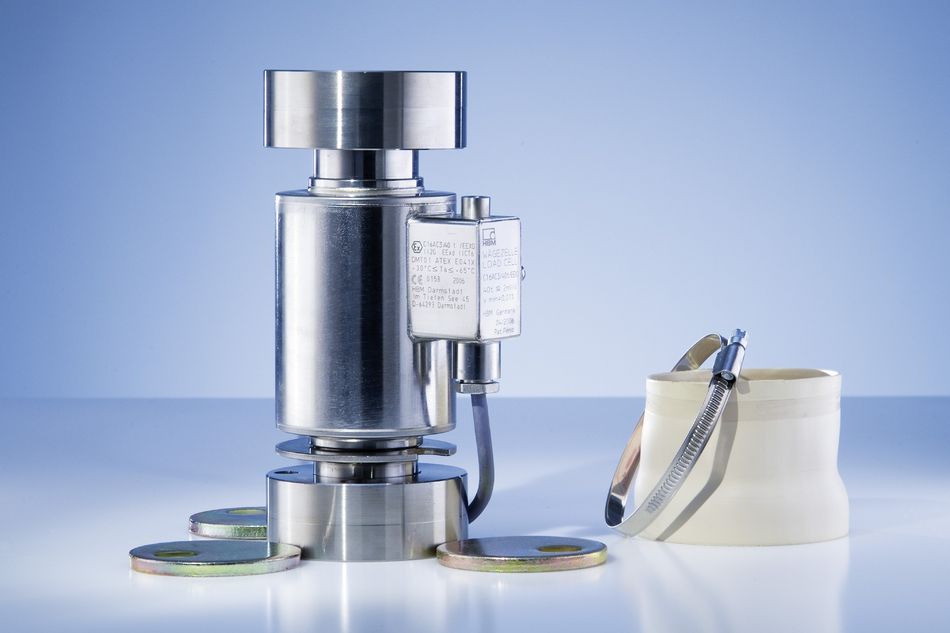
Compression Load Cells take load along a single principal axis. Canister and column designs are instrumented cylinders with a high aspect ratio, and they dominate high-capacity applications such as weighbridges and large silo installations.
Pancake Load Cells provide similar compression measurement in a shorter, low-profile package and are widely used in testing machines and structural measurement. Its low-profile family ranges from 4.45 N (1 lb) to 9000 kN (2 million lb), illustrating the wide compression load cell range. [5]
Single Column Load Cells are more sensitive to inclined loading than multiple column designs because of bending in the column, and canister load cells are far more susceptible to dynamic temperature changes than beam cells.
Load Pins, Load Buttons, and Tension Links
Load Pin replaces structural pins in applications such as cranes, sheaves, shackles, and winches, measuring shear directly within the existing load path.
Load Button Cells are miniature compression cells for very tight envelopes, common in machine and component testing.
Tension Links are self-contained assemblies for measuring tension force in slings and cables.
Hydraulic and Pneumatic Load Cells
Hydraulic Load Cells convert force into fluid pressure using a piston, diaphragm, and sealed oil chamber. The load acts on a piston against an elastic diaphragm sealing an oil-filled chamber, raising the fluid pressure in proportion to the force. Bourdon tube pressure gauge or precision pressure transducer reads the result, calibrated in force units.
Pneumatic Load Cells operate through force balance, using regulated air pressure to counter the applied force. The load is applied to one side of a corrugated diaphragm, and regulated air pressure is admitted to the other side through a nozzle and flapper arrangement until the diaphragm returns to its pre-loaded position. The balancing air pressure is then proportional to the applied force.
Multi-Axis Load Cells and Torque Transducers
Multi-axis force sensors resolve load into 2, 3, or 6 components, measuring force and torque simultaneously. Six-axis units are standard in robotics for force-controlled assembly and in biomechanics. Expect significant cross-axis coupling specifications and a calibration matrix rather than a single mV/V figure.
Recommended Reading: What is a Sensor? In-Depth Exploration and Comprehensive Guide to Engineering Principles and Applications
Load Cell Accuracy: What the Specifications Actually Mean?
The datasheet percentages are only meaningful once you know what they are measured against. Most are expressed as a percentage of rated output (RO) or full scale output (FSO).
Nonlinearity, Hysteresis, and Combined Error
Nonlinearity is the maximum deviation of the increasing calibration curve from a straight line. The reference line matters, and it differs by regime. Depending on the applicable standard or manufacturer, that reference may connect zero and rated output, use a point at 75% of the measuring range, or be calculated using a least-squares best-fit line.
Hysteresis is the difference in output at the same applied load depending on whether that load is approached while increasing or decreasing force. Repeatability, meanwhile, indicates how closely the load cell reproduces the same output during repeated measurements under identical conditions.
Rather than specify these separately, legal metrology uses a combined error envelope. It is "not considered appropriate to specify individual error limits for given characteristics," because an error envelope lets a manufacturer balance nonlinearity, hysteresis, and temperature effects on sensitivity against a single total.
High precision cells do publish individual numbers. Some FUTEK models, for example, list nonlinearity and nonrepeatability around ±0.02% of rated output. [6]
Creep and Minimum Dead Load Output Return
Creep is the change in output under constant load with everything else held constant. It is a real problem in tank weighing, where a vessel sits at near-constant load for hours. The creep tolerance is where standards diverge most, and the difference is not academic.
In a study of 65 load cells from 2.2 kN to 498 kN capacity, covering shear beam, single point, canister, and both C-shaped and S-shaped tension designs, Bartel and Yaniv at NIST found that 30-minute creep averaged approximately 84% of 60-minute creep, while creep recovery averaged about 86% of maximum creep. [7] Importantly, 6% of tested cells failed NTEP 60-minute creep requirements, compared with 62% failing the corresponding OIML evaluation, demonstrating that OIML creep requirements can be considerably more demanding.
Minimum Dead Load Output Return (MDLOR), identified as DR in OIML R 60, measures the change in zero output before and after sustained loading. OIML limits this shift to 0.5 verification intervals.
Temperature Effects
Two separate specifications apply: temperature effect on zero (minimum dead load output) and temperature effect on sensitivity (span). OIML R 60-1:2021 requires load cells to stay within the error limits over minus 10 degrees Celcius to plus 40 degrees Celcius unless narrower special limits are marked, and it caps the zero drift at the apportioning factor times the minimum verification interval per 5 degrees Celcius for classes B, C, and D, tightening to per 2 degrees Celcius for class A.
The asymmetry that catches people out: reducing utilization improves nonlinearity and hysteresis, but temperature effects on zero and span are fixed percentages of output at a given utilization and do not improve.
Selecting a Load Cell: Capacity, Utilization, and Environment
Sizing Capacity Step by Step
Total the Dead Load: vessel, platform, mixer, insulation, piping contribution, and any permanently attached hardware.
Add the Maximum Live Load, including overfill and dynamic effects from agitators, filling impact, or vehicle motion.
Divide by the Number of Load Cells, then apply a distribution factor. Load rarely splits evenly, so assume the worst loaded cell carries more than its nominal share.
Add Margin for shock, wind, and seismic loads where applicable.
Select the Next Standard Capacity above the result, then verify that the resulting utilization still gives you the resolution you need.
Confirm the Safe Load Limit and the ultimate load limit cover your worst credible overload.
Why Utilization Matters More Than the Datasheet?
The load cell performance depends not only on rated accuracy but also on how much of the measuring range you actually use.
VPG measured a 500 kg cell at 20%, 40%, 60%, and 80% utilization. Going from 80% down to 20% utilization improved nonlinearity by a factor of 7 and hysteresis by a factor of 8. [1] The creep and MDLOR improve too, scaling approximately as:
y = (Dmax / Emax) x x
where b is the error over the full measuring range, Emax is rated capacity, Dmax is the maximum utilized load, and y is the resulting error at that utilization. Because system dead load contributes directly to Dmax, a heavy vessel eats into this benefit even when the live load is small.
The relevant metric is the minimum measuring range:
MMR (mass) = v(min) x n(max), or MMR (%) = n(max) x 100 / gamma
where v(min) = Emax / gamma. For an SSB 1 t C3 cell with v(min) = Emax / 10000, MMR is 1000 x 3000 / 10000 = 300 kg, which is 30% of capacity. That is the smallest span over which full specification is maintained, and it can sit anywhere between zero and rated capacity.
The practical rule: oversizing for mechanical safety is usually free in accuracy terms and buys you overload margin, as long as your indicator can still resolve the signal.
Environmental Protection and Sealing
Moisture ingress is the leading cause of load cell failure in industrial service. Protection grades range from potted and environmentally protected to welded seals, and up to fully hermetically sealed designs with glass-to-metal cable feedthroughs. For washdown, outdoor, or corrosive service, specify stainless steel construction and hermetic sealing, and check the humidity class on the certificate. The NH-marked cell has not undergone the humidity test.
Signal Conditioning and Instrumentation
The load cell produces a very small electrical signal, so accurate measurement depends heavily on excitation stability, wiring, amplification, analog-to-digital conversion, and calibration.
Excitation and Wiring
The four-wire load cell connection carries excitation positive and negative, plus signal positive and negative. Its main limitation is cable resistance. Voltage lost in the excitation leads reduces the voltage reaching the Wheatstone bridge, while temperature-dependent changes in cable resistance can introduce measurement drift.
The six-wire load cell connection adds two sense leads that measure the actual excitation voltage at the bridge. The instrument can then compensate for cable losses. Six-wire configurations are recommended for long cable runs, large temperature variations, or installations containing junction boxes, trimming resistors, barriers, or surge protection devices.
But the hazardous-area barriers can introduce additional offset and span errors as their resistance or leakage current changes with temperature. These effects can be reduced through temperature-controlled barriers, balanced sense-line connections, or appropriately compensated approved barriers.
The wire colors vary between manufacturers, so connections should always be confirmed from the datasheet or with an ohmmeter rather than relying solely on color conventions.
Analog Front End and ADC Requirements
Load cell outputs are extremely small. The 2 mV/V sensor excited at 5 V produces only 10 mV at full scale. To achieve 20,000 noise-free counts, the electronics must resolve approximately:
(2 mV/V) x (5 V) / 20000 = 500 nV
and because readings must not toggle between codes, internal noise performance should be roughly ten times better than the displayed resolution, so about 50 nV. TI recommends a 24-bit converter delivering more than 18 bits of noise-free resolution with calibrated accuracy over temperature better than 0.5%.
Three design choices follow:
Use a Delta-Sigma Architecture: Load signals change slowly, and you need resolution, not bandwidth.
Amplify with a Low-Noise, Low-Drift PGA: Typically with gains of 64 or 128 for direct bridge measurement.
Use Ratiometric Measurement: Where bridge excitation also serves as the ADC reference. This cancels excitation-voltage variations in the measurement.
This implies that a 1-kilo-ohm bridge, 5 V excitation, 2 mV/V sensitivity, 10 mV full-scale signal, more than 20,000 noise-free counts at 100 SPS, and settling under 25 ms.
Prototyping with Arduino
For prototypes and low-cost weighing systems, an Arduino combined with an HX711 or NAU7802 provides an inexpensive 24-bit load cell interface. Calibration typically requires zeroing the unloaded sensor, applying a known reference mass, and calculating a scale factor.
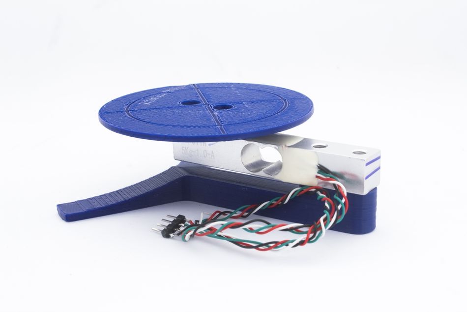
These platforms are suitable for experimentation, indication, and basic control. However, they do not replace certified weighing indicators in legal-for-trade applications, where the complete measurement chain must satisfy applicable metrology and type-approval requirements.
Recommended Reading: Arduino UNO Pinout: Comprehensive Guide for Engineers and Students
Installation Errors That Ruin Accuracy
A cell that meets Class C3 on a test bench can perform far worse installed. The load cells are ranked under optimum load introduction, and reproducing those conditions in the field is "extremely difficult (if not impossible)."
Load Introduction: Side Loads and Eccentric Loading
The load cell measures most accurately when force acts along its intended principal axis. The common loading errors can disturb the measurement:
Eccentric Loading: Force remains parallel to the measurement axis but is applied away from its center.
Concentric Inclined Loading: Force passes through the center but acts at an angle.
Eccentric Inclined Loading: Force is both angled and offset.
Side Loading: Force acts perpendicular to the measurement axis.
For an inclined load, the axial component is:
Lp = La × cos(α)
where La is the applied load, and α is the inclination angle.
Installation hardware is therefore critical. Rocker pins, self-aligning mounts, spherical bearings, and rod ends allow the mechanical structure to move without transferring excessive transverse forces into the sensor. Following the recommended mounting orientation (shared by the manufacturer) can also reduce errors caused by eccentric loading.
Stay Rods, Piping, and Mechanical Bypass
Anything that connects a weighed vessel to its surroundings carries part of the load. Pipes, hoses, cables, bellows, and conduits all shunt force around the load cells and introduce non-repeatability, hysteresis, and span error.
Because the load cell must deflect to measure, a horizontal stay rod is forced to tilt, and its side force acquires a vertical component:
Fp = Fs × d / l
where Fs is the horizontal force, d is the load cell deflection, and l is the stay-rod length.
Longer stay rods and load cells with lower rated deflection minimize this effect. Because the horizontal force can vary with operating conditions, calibration generally cannot remove the resulting error reliably.
Thermal Gradients
Internal temperature compensation only works when the whole cell is at one stable temperature. A gradient across the cell, from sunlight on one side or a heated vessel above it, produces errors that can far exceed the permitted limits.
Temperature settling times are longer than most engineers expect. VPG cites 1 hour per 10 degrees Celcius for small compact beams, rising to 5 hours per 10 degrees Celcius or more for canisters, and recommends sun shields outdoors and insulation pads between load cells and heated vessels. [1]
This is a genuine reason to prefer beam cells over canisters where capacity allows, and to ask the supplier for a temperature-settling-time specification.
Calibration and Traceability
ASTM E74 and the Verified Range of Forces
For force measurement in materials testing and calibration laboratories, the governing US practice is ASTM E74, which classifies an instrument by the range over which it has been verified rather than by a blanket accuracy figure.
The key quantity is the lower limit factor (LLF), derived from the calibration data fit. The classes are multiples of it:
Class A Loading Range = 400 x LLF
Class AA Loading Range = 2000 x LLF
For a 4.45 kN (1000 lbf) cell with an LLF of 0.44 N (0.1 lbf), the Class A range starts at 178 N (40 lbf) and the Class AA range starts at 890 N (200 lbf). At the Class A lower limit, the device is within 0.25% of the applied force; at the Class AA lower limit, within 0.05%.
The practical consequence: a load cell is not usable across its whole range for high accuracy work, and the bottom of the range is where accuracy claims collapse.
Field Calibration
For weighing systems, calibration means applying known masses and adjusting zero and span in the indicator. Once test weights are impractical, such as for a large silo, options are material substitution, hydraulic calibration rigs, or electronic simulation, each with a documented accuracy penalty.
Calibrate over the range you will actually use, in the installed condition, after the system has thermally stabilized. Calibrating a tank at ambient and operating it hot will not give you the accuracy on the certificate.
Recommended Reading: What Is a Fuel Cell? Theory, Components, Types, and Applications
Common Mistakes and Troubleshooting
Load cell problems often stem from installation, environmental conditions, or signal-chain limitations rather than failure of the sensing element itself.
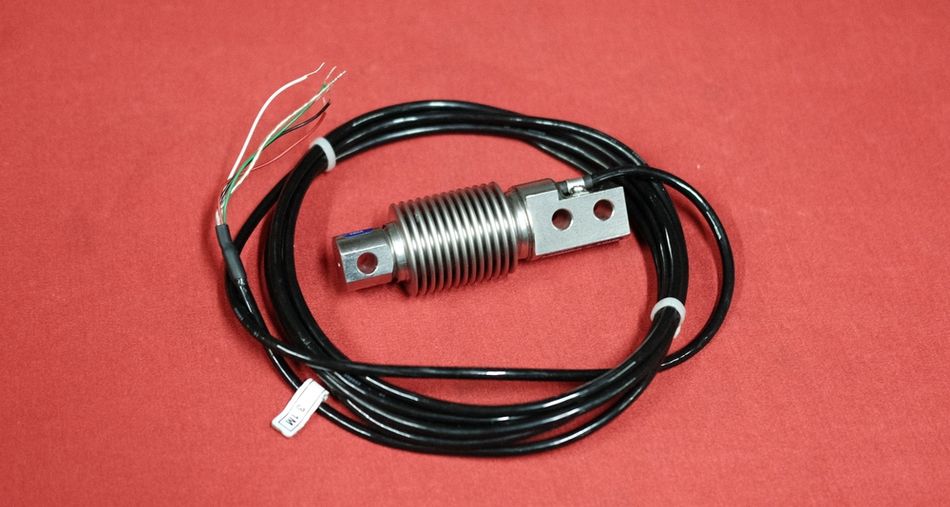
The following symptoms can help identify the most likely source.
Zero Drifts while the Load Remains Constant: Creep or gradual settling of a mechanical bypass may be responsible. Compare the drift against the specified creep limit and inspect piping, hoses, supports, and stay rods for unintended load paths.
Readings Change without a Load Change: Thermal gradients from sunlight, heated vessels, or changing ambient conditions can shift output. Provide shielding or insulation and allow sufficient temperature-settling time.
Poor Repeatability: Side loading, structural binding, or misaligned mounts are common causes. Verify that mounting surfaces are level and that the weighed structure does not contact surrounding equipment.
Span Error cannot be Calibrated Out: Check for vertical forces generated by stay rods and temperature-dependent resistance in Zener barriers. Longer stay rods and six-wire sense connections may reduce these errors.
Noisy or Unstable Readings: Calculate the available microvolts per division. Improve grounding and shielding, separate signal cables from power wiring, and consider six-wire connections.
Nonlinearity exceeds the Datasheet Specification: Excessive utilization, off-axis forces, or poor load introduction may be responsible. Review capacity and mounting.
Failure after Washdown: Suspect moisture ingress and verify the IP rating, sealing method, and humidity classification.
Legal Metrology Failure: Confirm that v(min), division size, load cell class, and system configuration satisfy the required approval criteria.
Recommended Reading: What is a Strain Gauge? Working, Types, and Selection
Conclusion
The load cell looks like a simple component, and the physics is straightforward: force to strain, strain to electrical resistance, resistance to an electrical signal via a Wheatstone bridge. What makes force measurement hard is everything around that chain.
The decisions that determine whether you hit your accuracy target are: choosing a type whose loading tolerance matches how cleanly you can introduce load, sizing capacity so that utilization works in your favor rather than against it, checking v(min) against the division size before you commit, designing a front end that resolves hundreds of nanovolts repeatably, and installing the cell so no mechanical path bypasses it.
If you manage these rightly, a commodity C3 load cell will hold its specification for years. If the installation gets wrong, no amount of calibration or specification will recover the accuracy you paid for.
Frequently Asked Questions
Q. What is a load cell used for?
A. Load cells measure force or mass by converting load into an electrical signal. They are used in industrial weighing systems, truck and railway scales, tank and silo inventory measurement, material testing machines, crane and lifting safety systems, robotic force control, medical devices, bathroom scales, and laboratory balances.
Q. How does a load cell work?
A. Applied force deforms a machined spring element. Bonded strain gauges on that element change electrical resistance in proportion to the strain, and a Wheatstone bridge converts the resistance change into a differential voltage proportional to load. That signal, typically 2 mV per volt of excitation at rated capacity, is amplified and digitized.
Q. What are the main types of load cells?
A. The strain gauge families are bending beam, planar beam, single point, shear beam, S-type (S-beam), canister and column, pancake or low profile, load button, load pin, and tension link, plus multi-axis units that resolve force and torque. Non-strain-gauge types include hydraulic load cells (Bourdon tube readout) and pneumatic load cells (air pressure force balance).
Q. What is the difference between a load cell and a force sensor?
A. In general use, load cell means a calibrated force transducer built for accurate static or slowly changing measurement, usually strain gauge based. Force sensors are a broader category covering piezoelectric, capacitive, and optical devices, some of which suit dynamic or impact measurement where a load cell is less appropriate. Weight sensors and load sensors are informal synonyms for load cells in weighing contexts.
Q. What does C3 mean on a load cell?
A. C3 is an accuracy class designation: Class C with a maximum of 3,000 load cell verification intervals, since the number is stated in units of 1,000. OIML R 60-1:2021 caps Class C at 10,000 intervals. Full classifications may also state the manner of loading, special temperature limits, and a humidity class.
Q. Can I use an Arduino to read a load cell?
A. Yes. An HX711 or NAU7802 breakout provides the 24-bit bridge front end, and calibration is a two-point procedure using a known mass. This is suitable for prototypes, indication, and control, but not for legal-for-trade weighing, which requires an approved indicator.
Q. How accurate are hydraulic and pneumatic load cells?
A. Lower than strain gauge cells. Published figures are around 0.1% of scale with about 0.02% resolution for hydraulic types up to roughly 2.45 MN, and about 0.5% of full scale for pneumatic types up to roughly 24.5 kN. Their advantage is that they need no electrical excitation at the sensing point.
References
[1] VPG Force Sensors. Load Cell Accuracy in Relation to the Conditions of Use [Cited 2026 August 16] Available at: Link
[2] Micro-Measurements. Crossing Over the Wheatstone Bridge. StrainBlog [Cited 2026 August 16] Available at: Link
[3] SparkFun Electronics. Getting Started with Load Cells. [Cited 2026 August 16] Available at: Link
[4] Texas Instruments. SBAA357: Designing High-Performance On-Board Weighing (OBW) Systems in Commercial Vehicles [Cited 2026 August 16] Available at: Link
[5] Interface. Types of Load Cells 101 [Cited 2026 August 16] Available at: Link
[6] FUTEK Advanced Sensor Technology. How a Strain Gauge Load Cell Works? [Cited 2026 August 16] Available at: Link
[7] Bartel, T. W. and Yaniv, S. L. Creep and Creep Recovery Response of Load Cells Tested According to U.S. and International Evaluation Procedures [Cited 2026 August 16] Available at: Link
[8] Morehouse Instrument Company. Easy to Use ASTM E74 Load Cell Selection Guide [Cited 2026 August 16] Available at: Link
in this article
1. Key Takeaways2. Introduction3. How a Strain Gauge Load Cell Works4. Types of Load Cells and Where Each Fits5. Load Cell Accuracy: What the Specifications Actually Mean?6. Selecting a Load Cell: Capacity, Utilization, and Environment7. Signal Conditioning and Instrumentation8. Installation Errors That Ruin Accuracy9. Calibration and Traceability10. Common Mistakes and Troubleshooting11. Conclusion12. Frequently Asked Questions13. References